HAL Id: tel-03163339
https://tel.archives-ouvertes.fr/tel-03163339
Submitted on 9 Mar 2021
HAL is a multi-disciplinary open access
archive for the deposit and dissemination of sci-entific research documents, whether they are pub-lished or not. The documents may come from teaching and research institutions in France or abroad, or from public or private research centers.
L’archive ouverte pluridisciplinaire HAL, est destinée au dépôt et à la diffusion de documents scientifiques de niveau recherche, publiés ou non, émanant des établissements d’enseignement et de recherche français ou étrangers, des laboratoires publics ou privés.
Highly oriented conducting polythiophene films for
thermoelectric applications
Vishnu Vijayakumar
To cite this version:
Vishnu Vijayakumar. Highly oriented conducting polythiophene films for thermoelectric applications. Other. Université de Strasbourg, 2020. English. �NNT : 2020STRAE004�. �tel-03163339�
ÉCOLE DOCTORALE Physique et Chime-physique
INSTITUT CHARLES SADRON UPR 22
THÈSE
présentée par :Vishnu VIJAYAKUMAR
soutenue le : 07 février 2020
pour obtenir le grade de : Docteur de l’université de Strasbourg Discipline/ Spécialité : Physique et Chimie-physique
Highly oriented conducting polythiophene
films for thermoelectric applications
THÈSE dirigée par :
Dr. Brinkmann Martin Directeur de Recherche, Institut Charles Sadron, Strasbourg
RAPPORTEURS :
Prof. Christian Müller Professeur, Chalmers University of Technology, Suède
Dr. Alexandre Carella Chercheur, CEA, Grenoble, France
Examinateurs :
Prof. Sabine Ludwigs Professeur, Université de Stuttgart, Allemagne
Dr. Nicolas Stein Maître de conférences, Université de Lorraine, France
“Nothing in life is to be feared, it is only to be understood. Now is the time to understand more, so that we may fear less.” ― Marie Curie
Acknowledgements
First of all, It is my genuine pleasure to express my sincere gratitude to my PhD supervisor Dr. Martin Brinkmann, who was always there to help me with great patience and interest throughout these years. Over the course of the PhD, we had great scientific and personal discussions. Several ideas in this thesis were the outcomes of these scientific discussions. Joining his lab was the best decision of my life. Thank you so much Martin for giving me this opportunity and without your help, I would not accomplish this milestone.
I would also like to thank my co-supervisor Dr. Laure Biniek for her support and the time she devoted to my PhD, where we had a lot of discussions. Her suggestions and discussions helped me to improve my scientific skills. Laure was very helpful and was always there and ready to answer my countless questions.
I would like to thank Dr. Nicolas Leclerc, Dr. Elena Zaborova and Pablo Durand for providing the polymers and doping materials and for all the experimental support given during the revision of the manuscripts.
I would like to thank Mr. Laurent Herrmann for helping me with the Seebeck coefficient and electrical conductivity measurements.
I would like to thank Dr. Mark Shmutz and Dr. Christian Blank for their help and support with the transmission electron microscopic experements.
I thank Dr. Bernard Lotz for all his suggestions and advises during my PhD. It was an honor to work with you and I will always keep your words in my heart.
Also thank you Dr. Thomas Heiser and Dr. Jerome Combet for accepting our invitation to be the Jury members of my mid-thesis presentations.
To my fellow PhD students and group members Marion Brosset, Huiyan Zeng and
Viktoriia Untilova, thanks for the pleasent time and friendship and I wish you all the very
best and good luck to yourselves. Moreover I would like to note a special thanks to my friend Marion for helping me with all the French administrations and also for organizing and co-ordinating everything on the day of my PhD defence.
I would like to thank the young PhD student Yuhan Zhong for all the nice discussion we had during my second year of PhD. I wish you a great PhD ahead with lots of results. To my previous PhD colleagues Dr. Amer Hamidi-Sakr and Dr. Morgane Diebold for the great discussions we had during the first years of my PhD. I have learned alot from both of you and thanks for helping me with the initial administration procedures upon my arrival in the lab.
To the rest of the people in SYCOMMOR teamPhilippe, Amparoo, Jean Philippe, Alain, Dominique and to the young PhD students Ricardo, Duncan and Quentin, big thanks for all your help and co-operation during these three years.
I would like to express my sincere thanks to Mme. Odile Lemble, who was always pleasant, approchable and willing to assist me for all the difficult french administration during these three years. Thank you so much Odile.
To the lunch group memebrs, Geevarghese, Fedir, Anasthasiia, Eualaie, Jean, Othmene, Vaibhav and Justine for all the fun and absurd lunch time discussions.
I wish to thank my primary and high school teachers to create an enthusiasm about science in me.
Also, I would like to thank Dr. C. Vijayakumar for his valuable guidance in CSIR-NIIST during my research assistantship work on hybrid thermoelectric materials .
I wish to thank my parents, Vijayakumar and Sucheta. Big thanks for your support and advice, even when I had this crazy idea to do a PhD abroad. I was always worried about both and missed alot during these three years.
Finally to my sweet wife Anuja, thank you so much for all the patience, understanding and the support throughout these 3 years- without you this would not have been possible !
Table of contents
Thesis Introduction ... 1
Chapter 1. Fundamental concepts & state of the art ... 11
1.General aspects of conjugated polymers ... 12
1.1. Energy level design of conjugated polymers. ... 12
1.2. P3HT: The working horse among organic semiconductors ... 15
2. Semi-crystalline P3HT- lamellar morphology ... 17
2.1. Crystal structure of P3HT ... 20
3.Liquid – crystalline polymers with enhanced structural order... 22
3.1. Crystal structure of PBTTT ... 24
4. Controlling orientation of conjugated polymers ... 28
4.1. Orientation by mechanical rubbing ... 29
4.2. Orientation by friction transfer ... 34
4.3. Orientation by strain alignment ... 36
4.4. Orientation by using an orienting substrate (Epitaxy) ... 37
5. Anisotropy of charge transport ... 39
6. Thermoelectricity ... 42
6.1. Basic principles of thermoelectricity... 43
6.2. Thermoelectricity in conducting polymers ... 45
7. Doping of conjugated polymers ... 47
a) Electronic Process involved upon P-type doping ... 47
b) Charge carriers in conducting polymers ... 52
7.1. Factors influencing doping and thermoelectric properties of polythiophenes ... 54
a) Regioregularity, solid-state order and crystallinity ... 55
b) Thermal conductivity ... 55
c) Size and electron affinity of dopant and IE of polymer ... 56
d) Polymer orientation techniques ... 57
e) Doping methods and resulting thermoelectric properties of polythiophenes ... 58
i) Soution doping of polythiophenes……….58
ii) Sequential doping of polythiophenes……….61
7.2. Dopant induced structural changes in polythiophenes ... 63
7.3. TE properties of a few representative systems using P3HT and PBTTT ... 68
8. Conclusion ... 71
Chapter 2. Impact of alkyl side chain length on doping kinetics, crystal structure & thermoelectric properties of oriented PBTTT ... 83
1.Introduction ... 85
2. Results and discussion ... 88
2.1. Fabrication of highly oriented and conducting PBTTT thin films ... 88
2.2. Doping kinetics using polarized UV-Vis-NIR spectroscopy ... 90
2.3. Estimation of doping level and integer charge transfer. ... 97
2.4. Impact of alkyl side chain length on the structure and final doping concentration. ... 101
2.5. Anisotropy of thermoelectric properties ... 106
3. Conclusion ... 112
Chapter 3. Bringing conducting polymers to high order: towards conductivities beyond 105 S/cm and thermoelectric power factors of 2 mW.m-1.K-2 ... 119
1. Introduction ... 121
2. Results and discussion ... 124
2.1. Fabrication of highly oriented and conducting thin films ... 124
2.2. Structure and nanomorphology of doped thin films by transmission electron microscopy ... 125
2.3. Nanomorphology of the thin films ... 130
2.4. Spectroscopic signatures of doping: Polarized UV-Vis-NIR spectroscopy ... 132
2.5. Anisotropy of charge conductivity. ... 136
2.6. Anisotropy of the Seebeck coefficient. ... 141
2.7. Correlations between thermopower and charge conductivity in oriented conducting polymer films. ... 145
Chapter 4. Influence of dopant size and doping method on the thermoelectric properties of PBTTT
films doped with F6TCNNQ and F4TCNQ ... 158
1.Introduction ... 160
2. Results and discussion. ... 164
2.1 Fabrication of highly oriented conducting PBTTT thin films ... 164
2.2. Polarized UV-Vis-NIR spectroscopy ... 165
2.3. Angular distribution of dopant anions and polarons ... 168
2.4. Doping kinetics ... 174
3. Influence of the method of sequential doping on the charge conductivity. ... 178
4. Influence of doping method on Seebeck coefficients and correlations with charge conductivity. . 183
5. Impact of doping methods on the crystal structure ... 186
6. Estimation of doping level and mobilities ... 191
7.Conclusion... 195
Conclusions and perspectives ... 203
Experimental details ... 213
1. Polymer synthesis and characterization ... 214
1.1.General procedure for the synthesis of polymers ... 214
2. preparation of conducting polymer films ... 216
2.1 Preparation of glass slides ... 216
2.2 Thin film preparation-orientation by high-temperature rubbing... 216
2.3 Doping methods ... 218
A) F4TCNQ doping of polythiophenes... 218
B) FeCl3 doping of polythiophenes ... 218
C) Incremental concentration doping (ICD) and direct doping (DD) of polythiophenes using F6TCNNQ and F4TCNQ. ... 219
3. Sample preparation for TEM ... 219
A) F4TCNQ doped PBTTT ... 219
C) Incremental concentration doping using F6TCNNQ and F4TCNQ ... 220
4. Scanning electron microscopy ... 221
5. Scanning transmission electron microscopy- dispersive X-ray spectroscopy (STEM-EDX) ... 221
6. Cyclic voltammetry ... 221
7. Polarized UV-Vis-NIR spectroscopy ... 222
8. Differential Scanning Calorimetry ... 222
9. Electrical conductivity and thermopower measurements ... 222
Abbreviations used in the text
ACN Acetonitrile
AFM Atomic force microscopy
Bi2Te3 Bismuth Telluride
Bu4NPF6 Tetrabutylammonium hexafluorophosphate
CMS Charge modulated spectroscopy
CSA Camphor sulphonic acid
CTS Charge Transfer State
D Diffusion coefficient
DD Direct doping
DBSA Dodecyl benzene sulphonic acid
DCM Dichloromethane
DFT Density functional theory
DSC Differential scanning calorimetry
DR Dichroic ratio
EBSA Ethyl-benzene sulphonic acid
EDX Energy dispersive X-ray spectroscopy
Eg Energy gap
EPR Electron paramagnetic resonance spectroscopy
FFT Fast Fourier Transform
F6TCNNQ 2,2-(perfluoronaphthalene-2,6-diylidene)-
dimalononitrile Fe (TFSI)3 Ferric (iii) triflimide
Fe+3-tos
3 .6H2O Iron(III) p-toluenesulfonate hexahydrate
FeCl3 Ferric Chloride
FTS Perflurooctyl-trichlorosilane
GIXD Grazing X-ray diffraction measurement HH Head to head
HOMO Highest occupied molecular orbitals HOPG Highly oriented pyrolytic graphite HT Head to tail
ICD Incremental concentration doping
IE Ionization Energy
IR Infrared spectroscopy
KBrBz Potassium 4-bromobenzoate
LUMO Lowest unoccupied molecular orbitals
Mw Molecular weight
Mn Number average molecular weight
NaPSS Sodium polystyrene sulfonate
N-DMBI 4-(2,3-Dihydro-1,3-dimethyl-1H-benzimidazol-2-yl)-N,N- dimethylbenzenamine
N-DPBI
4-(1,3-Dimethyl-2,3-dihydro-1H-benzoimidazol-2-yl)-N,N- diphenylaniline
OCL Orientation correlation length OFET Organic field effect transistor
OP Order parameter
PA Polyacetylene
PDI Polydispersivity index
P(NDI2OD-T2) Poly ([N,N-bis(2-octyldodecyl)-naphthalene-1,4,5,8-
bis(dicarboximide)-2,6-diyl]-alt-5,5-(2,2-bithiophene))
P3BT Poly (3-butylthiophene)
P3HT Poly (3-hexylthiophene)
PBTTT Poly(2,5-bis(3-alkylthiophene-2-yl)thieno[3,2-b]thiophene)
PC71BM Phenyl-C71-butyric acid methyl ester
PDMS Polydimethylsiloxane
PEDOT: PSS Poly(3,4-ethylenedioxythiophene)polystyrene sulfonate
PF Power factor
PFO Poly(9,9′-dioctyl-fluorene) Pmax Maximum power
POM Polarized optical microscopy
PSCs Polymer semiconductors PTFE Polytetrafluoroethylene
PDOPT Poly(3-(4-octylphenyl)-2,2′-bithiophene) R internal Internal resistance
Rload External load
S Seebeck coefficient
SCE Standard calomel electrode SEM Scanning electron microscopy
STM Scanning tunneling microscopy
SWCNT Single walled carbon nanotube
TCB 1,3,5-trichlorobenzene TCNQ Tetracyanoquinodimethane
TEM Transmission electron microscopy
Tos Tosylate TT Tail to tail VB Valance band ZT Figure of merit σ Electrical Conductivity Thermal Conductivity µ Mobility Wavelength
1
Thesis introduction
2
Thesis introduction
The energy demand of the world is increasing day by day. In particular, the world’s electricity demand is steadily increasing from≈13 TW in 2012 to an expected 26 TW in 2050.[1] Currently, we are depending mainly on renewable energy sources such as
sunlight, wind and tidal energies. They can be used repeatedly and are naturally replenishing sources of energy. The conversion efficiency of solar energy to useful electricity by solar panels and solar thermal plants is estimated as only 40%. More than 60% of global energy is wasted in the form of heat.[2][3] The conversion of waste heat to
electricity may play an important role in our current challenge to develop alternative energy technologies to reduce our dependence on fossil fuels and reduce greenhouse gas emissions. Highly efficient thermoelectric materials can be one solution for converting this huge amount of waste heat to electricity. Inorganic materials such as silicides, Heusler alloys and metallic oxides are widely used for high temperature (800K) thermoelectric applications. These materials provide excellent thermoelectric performances and are mainly composed of non-toxic elements.[4] Moreover, the
situation below 500 K is different. The room temperature and commercially available thermoelectric generators are mainly composed of a special class of inorganic materials called chalcogenides. They are composed of highly toxic elements such as Lead (Pb). The high cost, toxicity and poor processability of these heavy elements limited their applications in various thermoelectric technologies[3].
The ability to convert conjugated polymers from insulating to highly conducting form triggered their use in different electronic applications such as organic field-effect transistors[5][6] (OFET), organic solar cells, organic light-emitting diodes[7] (OLED) and
organic thermoelectrics[8]. Pioneering work by Heeger and coworkers on doped
Thesis introduction
3
as thermoelectric materials).[9] Unlike inorganic materials, these organic materials are
characterized by their easy processability. They are composed of abundant elements such as carbon, nitrogen, sulphur and oxygen and they possess lower thermal conductivity (0.37 W m−1 K−1) than inorganic materials.[10]. Moreover, they are flexible
and they can be processed into large-area devices using suitable methods such as slot-die coating, inkjet printing, brush coating and roll-to-roll coating. Both, flexibility and easy processability of organic conducting polymers results in reduced production costs and lead to the production of cheap organic-based devices, which are now available on the market.
The field of organic thermoelectrics received considerable attention after the publication of the seminal work of Crispin[8] and coworkers on poly (ethylene
dioxythiophene) (PEDOT). Crispin et. al[8] have shown that accurate control of the
oxidation level combined with the low thermal conductivity of PEDOT can lead to high ZT values of 0.25 at room temperature. Such performance is good enough for thermoelectric device applications. This discovery triggered much interest, on TE polymers. Doped polythiophenes such as P3HT and PBTTT showed high thermoelectric (TE) performances due to their semi-crystalline or liquid crystalline nature[11][12].
Moreover, studies by Chabinyc[13] and coworkers proposed that the thermoelectric
potential (PF) of a doped conducting polymer can be improved by increasing the conductivities of conjugated polymer from the relation PF1/2. Following this work,
most of the studies on thermoelectric polymers focused mainly on improving the electrical conductivity of the doped polymers.
A similar approach was followed in the frame of this thesis. Our main focus was to improve the thermoelectric properties of conducting polymers by improving their crystallinity and by introducing long-range order and orientation. We used a method
Thesis introduction
4
called high temperature rubbing, which allows to align a large variety of conjugated polymers[14]. Sequential doping of the oriented thin films prepared by this approach
produced highly conducting anisotropic films with high degrees of optical, structural and thermoelectric anisotropies. These highly anisotropic conducting polymer thin films are ideal model systems to probe the TE properties both parallel and perpendicular to the chains. They provided experimental evidence of the anisotropic charge transport mechanisms. Moreover, combining polarized UV-Vis-NIR spectroscopy and transmission electron microscopy (TEM) provided a better understanding of the location of the dopant anions in these oriented polythiophene thin films. A clearer picture of dopant induced structural changes in the polymeric unit cells was obtained from electron diffraction measurements.
The first chapter (Chapter 1) in my thesis is mainly dealing with the state of the art and basic concepts, which are relevant to my topic of research. The first section of this chapter is mainly dealing with general aspects of conjugated polymers such as their bonding, energy levels, chemical structure, crystal structure and different orientation methods. A short discussion about crystal structure, experimental evidence for the semi-crystalline nature of conventional regioregular P3HT and liquid semi-crystalline PBTTT is included. The second part of the chapter is dealing with the basic principles and concepts of thermoelectricity. This is followed by a brief discussion about different doping methods used for doping conducting polymers. At the end of this chapter, we present the impact of doping on the crystal structure of PBTTT and P3HT. Finally, a summary of representative thermoelectric performances in p-doped polythiophenes PBTTT and P3HT is discussed.
In Chapter 2, we mainly investigate the impact of the side chain length of PBTTT (C8, C12,
2,3,5,6-tetrafluoro-7,7,8,8-Thesis introduction
5
tetracyanoquinodimethane (F4TCNQ) into the side chain layers of PBTTT. Doping of
polymer semiconductors such as PBTTT with acceptor molecules such as (F4TCNQ) is
widely used to tune the charge transport and thermoelectric (TE) properties in thin films. However, the mechanism of dopant insertion in the polymer matrix, the insertion kinetics and the ultimate doping levels were only marginally investigated. Electron diffraction measurements on these doped thin films showed that the Intercalation of F4TCNQ into the layers of side chains of PBTTT results in an expansion of the lattice along
the side chains and the contraction along the -stacking direction for all polymers. The extent of lattice expansion decreases with increasing side chain length. UV-Vis-NIR spectroscopy demonstrates integer charge transfer for all investigated PBTTTs. The doping kinetics and final doping level depend on both the side chain length and packing. Highly disordered n-octyl and crystalline n-octyldecyl side chain layers tend to hamper dopant diffusion in the side chain layers contrary to n-dodecyl side chains that can host the highest proportion of dopants. Consequently, the best TE properties are observed for C12-PBTTT films. Alignment of the polymers enhances significantly the TE
performance by increasing the charge conductivity and the thermopower along the rubbing direction. Aligned films of C12-PBTTTshow charge conductivities of 193 S/cm
along the rubbing direction and power factors of approx. 100 µW.m-2.K-1 .
Chapter 3 compares the TE properties of P3HT and PBTTT upon doping with a strong
oxidizing agent, namely FeCl3. FeCl3 doping of aligned films results in charge
conductivities up to 2×10⁵ S/cm and metallic-like thermopowers similar to iodine-doped
polyacetylene. The films are almost optically transparent and show strongly polarized near infra red polaronic bands (dichroic ratio > 10).
The comparative study of structure-property correlations in P3HT and C12-PBTTT
Thesis introduction
6
i) Achieve high in-plane orientation of conjugated polymers with a high persistence length ii) ensure uniform chain oxidation of the polymer backbones by regular intercalation of dopant molecules in the polymer structure without disrupting the alignment of -stacked layers and iii) maintain a percolating nano-morphology along the chain direction.
The highly anisotropic conducting polymer films are ideal model systems to investigate the correlations between thermopower S and charge conductivity . A scaling law S-1/4 prevails along the chain direction but a different S -ln relation is
observed perpendicular to the chain direction, which was previously observed by Mateeva[15] et. al for stretch aligned polyaniline. This suggests two different charge
transport mechanisms parallel and perpendicular to the polymer chains. The simultaneous increase of charge conductivity and thermopower along the chain direction results in a substantial improvement of thermoelectric power factors up to 2 mW.m-1. K-2 in C
12-PBTTT
Chapter 4 is a comparative study of the effect of F6TCNNQ and F4TCNQ doping on the
crystal structure and thermoelectric properties of oriented C12-PBTTT films. F4TCNQ
doping of organic semiconductors such as P3HT and PBTTT has been widely documented in the recent literature. This chapter focuses mainly on doping of C12-PBTTT using a new
doping agent, namely F6TCNNQ. Unlike F4TCNQ, F6TCNNQ doping of polythiophenes has
been marginally studied. This dopant is chosen because of its deeper LUMO energy level of -5.3 eV, versus -5.1 eV for F4TCNQ, that can enhance charge transfer between C12
-PBTTT and F6TCNNQ. Oriented C12-PBTTTthin films are prepared by high temperature
rubbing and sequentially doped with F6TCNNQ using a new doping method, called
“incremental concentration doping” (ICD). The ICD method implies that a given sample is doped by dipping it successively in dopant solutions of increasing concentration. ICD
Thesis introduction
7
of C12-PBTTTusing F6TCNNQ leads to record electrical conductivities of 2430 S/cm and
thermoelectric power factors (PF) 530±200 µWm-1K-2 along the rubbing direction.
Moreover, this method leads to a higher electrical conductivity than the conventional doping method (direct doping). This study demonstrates that a progressive intercalation of dopants in PBTTT crystals using the ICD method helps preserve the high level of order initially present in the aligned C12-PBTTT films.
The diffusion coefficients of both F6TCNNQ and F4TCNQ anions have been determined
using the doping kinetics followed by UV-Vis NIR spectroscopy. A lower diffusion coefficient is observed for F6TCNNQ anions, demonstrating the size dependence of
diffusion coefficients into the polymer matrix. The longer and bulkier the anion, the lower its diffusion coefficient. Polarized UV-Vis-NIR spectroscopy on these doped thin films showed that F6TCNNQ- anions are better oriented in the layers of the alkyl side
chains as compared to F4TCNQ. The estimation of charge carrier mobilities indicates that
ICD leads to higher mobilities than DD. The lower degree of ordering of F4TCNQ- anions
Thesis introduction
8
Bibliography
[1] O. Bubnova, X. Crispin, Energy Environ. Sci. 2012, 5, 9345.
[2] M. G. Kanatzidis, Chem. Mater. 2010, 22, 648.
[3] M. Campoy-Quiles, Philos. Trans. R. Soc. A Math. Phys. Eng. Sci. 2019, 377, 20180352.
[4] D. Beretta, N. Neophytou, J. M. Hodges, M. G. Kanatzidis, D. Narducci, M. Martin- Gonzalez, M. Beekman, B. Balke, G. Cerretti, W. Tremel, A. Zevalkink, A. I. Hofmann, C. Müller, B. Dörling, M. Campoy-Quiles, M. Caironi, Mater. Sci. Eng. R
Reports 2018, DOI10.1016/j.mser.2018.09.001.
[5] H. Koezuka, A. Tsumura, T. Ando, Synth. Met. 1987, 18, 699.
[6] H. Sirringhaus, T. Kawase, R. H. Friend, T. Shimoda, M. Inbasekaran, W. Wu, E. P. Woo, Science (80 ). 2000, 290, 2123 LP.
[7] J. H. Burroughes, D. D. C. Bradley, A. R. Brown, R. N. Marks, K. Mackay, R. H. Friend, P. L. Burns, A. B. Holmes, Nature 1990, 347, 539.
[8] O. Bubnova, Z. U. Khan, A. Malti, S. Braun, M. Fahlman, M. Berggren, X. Crispin,
Nat. Mater. 2011, 10, 429.
[9] H. Shirakawa, E. Louis, A. MacDiarmid, C. Chiang, J. Heeger, J.C.S Chem. Comm
1977, 13, 578.
[10] R. Kroon, D. A. Mengistie, D. Kiefer, J. Hynynen, J. D. Ryan, L. Yu, C. Müller, Chem.
Soc. Rev. 2016, 45, 6147.
[11] M. Brinkmann, J.-C. Wittmann, Adv. Mater. 2006, 18, 860.
Thesis introduction
9
Sparrowe, S. Tierney, R. Wagner, W. Zhang, M. L. Chabinyc, R. J. Kline, M. D. McGehee, M. F. Toney, Nat. Mater. 2006, 5, 328.
[13] A. M. Glaudell, J. E. Cochran, S. N. Patel, M. L. Chabinyc, Adv. Energy Mater. 2015,
5, 1401072.
[14] L. Biniek, S. Pouget, D. Djurado, E. Gonthier, K. Tremel, N. Kayunkid, E. Zaborova, N. Crespo-Monteiro, O. Boyron, N. Leclerc, S. Ludwigs, M. Brinkmann,
Macromolecules 2014, 47, 3871.
[15] N. Mateeva, H. Niculescu, J. Schlenoff, L. R. Testardi, J. Appl. Phys. 1998, 83, 3111.
[16] Y. Karpov, T. Erdmann, M. Stamm, U. Lappan, O. Guskova, M. Malanin, I. Raguzin, T. Beryozkina, V. Bakulev, F. Günther, S. Gemming, G. Seifert, M. Hambsch, S. Mannsfeld, B. Voit, A. Kiriy, Macromolecules 2017, 50, 914.
Chapter 1: Fundamental concepts and state of the art
11
Chapter 1. Fundamental concepts & state of the art
This chapter is dedicated to the fundamental concepts and literature survey, that are relevant to this PhD thesis. The chapter is divided in two sections. The first section mainly focuses on the general aspects of conjugated polymers such as their bonding, energy levels, chemical structure, crystal structure and different orientation methods. A short description of the crystal structure and experimental evidence for the semi-crystalline nature of conventional regioregular P3HT is briefly introduced. Similarly, the crystal structure and experimental evidence for the thin film microstructure of PBTTT is also included. Later, a brief description of different polymer orientation techniques such as rubbing, strain alignment, friction transfer and epitaxy are discussed.
The second part of this chapter is mainly dealing with the thermoelectric properties and doping of polythiophene thin films. A short introduction and discussion of thermoelectric parameters such as electrical conductivity, Seebeck coefficient and power factors are provided. It is followed by a brief summary of different chemical doping methods used for polythiophenes e.g. solution doping, sequential doping, vapor phase doping. The consequence on the resulting thermoelectric properties is discussed. At the end of this chapter, we present the impact of doping on the crystal structure of PBTTT and P3HT. Finally, a summary of representative thermoelectric performances in p-doped polythiophenes PBTTT and P3HT is given.
Chapter 1: Fundamental concepts and state of the art
12
1. General aspects of conjugated polymers
1.1. Energy level design of conjugated polymers.
Conjugated polymers are organic macromolecules; they are characterized by a conjugated backbone with alternating double and single bonds. They have been the focus of enormous attention in the industrial and academic sector for various optoelectronic applications.[1] The main interest of conjugated polymers stems from the
π electron cloud. π electrons in the double bonds can be delocalized over several monomeric units in the polymer chains. Because of this electron delocalization from one monomer to another monomer, they have the ability to conduct electrical charges mainly along the conjugated backbone.
Figure 1.1. Schematic illustration of bonding and hybridization in ethylene molecule. Reproduced from (2) Let us consider the simplest case of the ethylene molecule. The ground state electronic configuration of the carbon atom is 1S2 2S22P2. In the case of ethylene, the carbon atom
is in sp2 hybridization and hence one electron in the 2S orbital can be promoted to the
vacant P orbital. Now the excited state configuration of the carbon atom become 1S2
2S12P3. The electrons in the 2S, 2P
x and 2Py orbital undergo sp2 hybridization, which gives
Chapter 1: Fundamental concepts and state of the art
13
atoms, which results in two carbon-hydrogen sigma bonds and the third orbital can be used to form a sigma bond with the next –CH2 units, resulting in a C-C sigma bond in
ethylene. The unused 2PZ orbitals undergo sidewise overlapping which produces the
bond in the ethylene molecule (see figure 1.1). The sidewise overlap of the 2PZ orbitals
results in a restricted rotation along the bond axis and gives rise to a planarized and stiff polymeric backbone.[2] The electrons present in the overlapped P
z orbitals do not belong
to one single bond but are delocalized over several atoms. The length scale of delocalization of these electrons is the conjugation length.
Figure 1.2. Evolution of HOMO and LUMO levels and the bandgap (Eg) with an increasing number of thiophene
repeating units and the resulting valence and conduction bands in polythiophene. Reproduced from (3)
The presence of alternating double and single bonds in conjugated polymers is responsible for the semiconducting properties of conjugated polymers. The smallest identical repeating unit of a polymer is called a monomer.
Chapter 1: Fundamental concepts and state of the art
14
During polymerization reactions, the chemical coupling of the monomers leads to orbital interactions and hence it results in an energy level splitting of the π (bonding) and π* (antibonding) orbitals. The π (bonding) orbitals are known as the highest occupied molecular orbitals (HOMO) and π* orbitals are known as the lowest unoccupied molecular orbitals (LUMO).[3] The valence band is arising from the π orbitals while the
π* orbitals form the conduction band (see figure 1.2). The energy gap between the HOMO and LUMO is the bandgap (Eg). The bandgap of a polymer depends on its chemical
structure and on the extent of conjugation. The longer the conjugation length, the smaller the bandgap. The sigma bond between the monomer preserves the structure of the molecule. The electrons in the π orbitals are free to undergo electronic and optical excitation and the charges can be delocalized along the polymer chains.
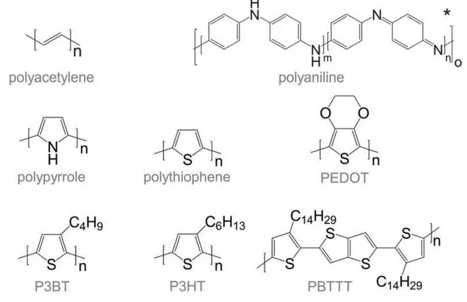
Figure 1.3. Chemical structures of most commonly used conjugated polymers. Reproduced from (3)
The conjugated polymers are semiconductors or insulators in their intrinsic form and they can be converted to a conductor via doping. In 1977, Heeger and coworkers
Chapter 1: Fundamental concepts and state of the art
15
reported high conductivity in iodine-doped polyacetylene.[4][5] Although doped
polyacetylene has limited commercial applications, its discovery led to major developments in the field of organic electronics. Soon after the discovery of doped polyacetylene, extensive research work was carried out on other conducting polymers such as polythiophenes, polyanilines and polypyrroles (see figure 1.3) for different industrial and scientific applications.
1.2. P3HT: The working horse among organic semiconductors
Soluble semi-conducting polymers attracted wide attention from the scientific community because of their excellent semiconducting properties and easy solution processability. This made them excellent candidates for flexible electronic devices prepared by roll-to-roll manufacture at low cost. Among semi-conducting polymers, regio-regular poly (3-hexylthiophene) (P3HT) is one of the most popular polymers as it combines unique crystalline and optoelectronic properties. The first synthesis of unsubstituted polythiophene was reported by Lin and coworkers in 1980.[6] This
discovery was followed by highly conducting Iodine doped thin films of these unsubstituted thiophenes by Yamamoto et al.[7]
Alkyl side chains were introduced on the polymeric backbone to help solubilize the polymer in common organic solvents.[7][8] Introduction of alkyl side chains on
polythiophene gives rise to three main regio isomers that differ in the position of the coupling between two successive monomers. The term “regio regularity” indicates the control of the configuration of the hexyl side chains. Depending on the position of the hexyl side chain, different regioisomers can be found in P3HT. The HH (head to head) regioisomer is produced by the coupling of two monomeric units through 2,2 position. The 2,5 coupling leads to the HT (head to tail) isomer and 5,5 coupling leads to the TT (tail to tail) isomer. The different monomers are represented in figure 1.4. Yamamoto
Chapter 1: Fundamental concepts and state of the art
16
and coworkers were the first to predict the existence of regioisomers in P3HT. The isomer with HT-HT coupling is called regioregular (rr) isomer.
Figure 1.4. A) Structures of possible coupling in 3-alkylthiophene dimers. B) Solid-state packing of HT coupled P3HT. C) Steric repulsion in P3HT as a result of the irregular coupling of monomers. Reproduced from (8)
The HH and TT isomers are regioirregular isomers. In a fully regioregular P3HT chain, all the monomeric units are coupled in head to tail manner.[8] In regioirregular P3HT (HH
and TT coupling), the steric repulsions between the adjacent alkyl side chains in the monomeric units can produce twists in the polymeric backbone. Such twisting reduces the conjugation length and packing efficiency and finally leads to poor optical and electrical properties. The rr-configuration produces thin films of P3HT with very high crystallinity. The high crystallinity is a key parameter for various optoelectronic and charge transport applications.
Chapter 1: Fundamental concepts and state of the art
17
rr-P3HT has a very high HOMO level (-5.1 eV) and possesses a bandgap of 2 eV. Highly crystalline P3HT was one of the first polymers to show high mobilities of 0.1 cm2/V.s in
field-effect transistors[9]. The main advantage of P3HT is that it can be crystallized very
easily from the solution to produce well-oriented crystals of large size. However, the grain boundaries are detrimental for charge transport and mobility. Depending on the processing method, different morphologies were obtained in P3HT. Crossland and coworkers were able to obtain a high FET mobility of 0.1 cm2/V.s in films with spherulitic
P3HT.[10] The high FET mobility was obtained due to the reduction in the grain
boundaries as a result of precise control of the nucleation and growth of anisotropic spherulitic structures in P3HT. Most interesting optical and charge transport properties in P3HT derived from its high crystallinity.
Single crystals were also obtained from P3HT. Similar to inorganic semiconductors, P3HT is also characterized by a crystal lattice (monoclinic form I) with well-defined unit cell parameters[11]. Unlike inorganic crystals, single crystals of P3HT show high anisotropy in
optical and electrical properties. For example, charge transport along the chain direction (c axis) is higher than that along the π stacking (b axis) direction (see figure 1.5 A). The poorest charge transport is along the alky side chain direction (a-axis). P3HT slowly emerged as a benchmark semiconductor polymer due to its easy synthesis procedure, solution processability and highly crystalline microstructure. More detailed investigations of the microstructure and transistor performance of P3HT provided important guidelines for the design of new polymer semi-conductors with enhanced device performance.[9][12,13][14–17]
2. Semi-crystalline P3HT- lamellar morphology
Many conjugated polymers are semi-crystalline in nature, which means that they consist of ordered polymer chains in the crystalline regions while the chain ends and chain folds
Chapter 1: Fundamental concepts and state of the art
18
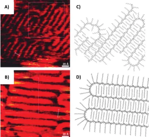
are mainly present in the amorphous parts of the polymer. So-called tie chains connect adjacent crystals through the amorphous regions of the polymer. Chain folding is an inherent nature of semi-crystalline polymers. The lamellar morphology of the polymer is mainly produced due to the crystallization mechanism. During crystallization, some of the chains tend to align in a specific manner and create ordered regions in the form of lamellar crystals or fibrils. The chain ends and chains folds cannot be accommodated in the crystals and are rejected to the amorphous phase of the semi-crystalline polymer. Hence, the lamellar structure implies a regular alternation of crystalline regions with ordered chains and amorphous regions with chain folds, chain ends, and chemical defects. The chain folding of poly(alkylthiophenes) was first revealed in the initial work of Mena – Osteritz, and coworkers. They were able to observe chain folding in regioregular poly(alkylthiophenes) prepared by epitaxial orientation on highly oriented pyrolytic graphite (HOPG) using scanning tunnelling microscopy (STM).[12,13] STM studies
evidenced the existence of chain folds in regioregular polythiophenes and also evidenced the interdigitation of the alkyl side chains (see figure 1. 6 A and B).
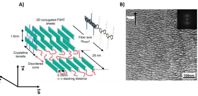
Further evidence for the semi-crystalline structure in P3ATs was obtained by Brinkmann et al. using transmission electron microscopy (see figure 1.5 B). [14–17]. Transmission
electron microscopic studies by Brinkmann and Rannou on epitaxially oriented P3HTs determined the molecular weight (Mn) for which the chain folding occurs. They proposed
that chain folding occurs for Mn 7.3 kDa. The presence of chain folding at higher
molecular weight leads to a saturation of the lamellar periodicity. Typically, a lamellar period of 28 nm is observed when Mn ≥ 18.8 kDa. Lower molecular weight fractions form
a crystalline phase without chain folds i.e. extended chain crystals. As the molecular weight increases, the number of chain folds inside the amorphous zones increases and the polymer becomes semi-crystalline. Moreover, another interesting observation is the increase in lattice parameter (aP3HT) with the increase in molecular weight of the
Chapter 1: Fundamental concepts and state of the art
19
polymer[18]. As the number of chain folds increases in the amorphous zones, chains
re-enter the crystalline part of the lamellae and exert a stress on the crystalline lattice i.e. increases the separation along the alkyl side chains.[17,19,20]
Figure 1.5. A) Schematic representation of the semi-crystalline morphology observed in an oriented P3HT film. B) Corresponding bright-field transmission electron microscopy image showing alternating crystalline and amorphous regions. A lamellar periodicity of 28 nm was obtained from the fast Fourier transform (FFT), which is shown in the inset. Reproduced from (14)
Apart from the molecular weight and regio regularity, the crystallinity and morphology of P3HT thin films can also be affected by processing conditions. The crystallization kinetics is an important factor that determines the crystallinity of a thin film. It has been observed that the polymer thin films deposited from higher boiling point solvents had higher crystallinity than the films deposited from low boiling solvents. For example, solution-processed thin films cast from chlorobenzene showed higher crystallinity than the films prepared from chloroform. This indicates that slower solvent evaporation is beneficial for higher crystallinity in solution-processed thin films.[21–23] Film deposition
Chapter 1: Fundamental concepts and state of the art
20
spin coating gives rise to less crystalline films than a slow drop-casting. The crystallinity and morphology of the thin films can be tuned by changing the molecular weight, processing conditions, solvent.
Figure 1.6. A&B) STM images showing chain folding in regioregular poly(alkyl thiophenes) epitaxially oriented on HOPG. The 2D crystalline packing C) and D) are obtained after modelling using semi-empirical calculations. Reproduced from (12&13)
Since our main focus of the thesis is to study the orientation and the anisotropic thermoelectric properties, the subsequent discussion is limited to the relevant crystal structures and orientation techniques of polymers.
2.1. Crystal structure of P3HT
As discussed earlier, regioregular poly (3-hexylthiophene) (rr-P3HT) is one of the most studied semi-crystalline polymers. Since it has high levels of crystallinity, the crystal structure of P3HT was an interest for crystallographers. Several studies helped to
A)
B)
C)
Chapter 1: Fundamental concepts and state of the art
21
elucidate the crystal structure of P3HT. In 1992, Prosa and coworkers reported a structural model for P3HT, which consists of well-defined “lamellae” made of π-stacked polymer backbones uniformly spaced by the layers of hexyl side chains.[24] Two
polymorphs were identified: form II has interdigitated side – chains contrary to form I, that is dominant in thin films used in devices.
Figure 1.7. A) Representation of the crystal structure of P3HTform I proposed by Kayunkid and coworkers. Fig B) represents the evolution of lattice parameters as a function of molecular weight. Reproduced from (11&18) An important structural refinement of form I P3HT was performed by Tashiro et. al[25] in
1997. The structural model was refined from X-ray data obtained on stretch-aligned P3HT films. Molecular modelling, polarized FTIR and Raman spectroscopy were combined to propose various models. One of the models implies an orthogonal unit cell with lattice parameters a= 16.63 Å, b= 7.75 Å, and c = 7.77 Å. Tashiro et. al proposed various structures that contain a different number of polymer chains in the unit cell. However, they were not able to discriminate between different possible models based on the results of X-ray diffraction.
Later in 2010, Brinkmann and coworkers proposed a new structural model for P3HT (form I) based on electron diffraction measurements on epitaxially oriented P3HT films
Chapter 1: Fundamental concepts and state of the art
22
from trichlorobenzene.[11] According to this model, P3HT crystallizes in a monoclinic unit
cell (see figure 1.5 A) with lattice parameters a= 16.6 Å, b= 7.8 Å, and c = 7.8 Å, = 86.5 °, a is the direction along the alkyl side chains (aP3HT), b is the direction along the π-π
stacking (bP3HT) and c is the direction along the polymeric backbone (cP3HT). From the
electron diffraction studies and crystallographic calculations, Kayunkid[11] et. al
predicted that the unit cell of P3HT contains 4 thiophene monomers. One chain is shifted with respect to the second chain along the c axis (see figure 1.7 A). The shift along the backbone is produced as a result of crystallization of the hexyl side chains into an orthogonal sublattice.[11] Moreover, they were able to assign a new space group P2
1/C
for the proposed structure. In the scope of this thesis, we used the P3HT crystal structure proposed by Kayunkid[11] and coworkers.
3. Liquid – crystalline polymers with enhanced structural order
Structure-property studies on P3HT provided important guidelines for the design of new polymer semiconductors with enhanced efficiency. The hexyl thiophene monomer lacks a centre of symmetry and this limits the various polymerization techniques to produce highly regioregular polymers, which is necessary to obtain highly crystalline films.[26,27]Also, the delocalized π-electron system of P3HT is susceptible to various
oxidation reactions. Thirdly the high side-chain density of P3HT prevents the interdigitation and reduces the long-range order in the polymer. Because of these limitations, new polythiophenes, mainly thienothiophene-based polymers were designed.
In 2006, McCulloch and coworkers reported very high mobilities of 0.2 to 0.6 cm2/V.s for
a new class of liquid crystalline polymers Poly(2,5-bis(3-alkylthiophene-2-yl)thieno[3,2-b]thiophene) (Cn-PBTTT).[28] It is a copolymer of thieno[3,2-b]thiophene and 4,4-dialkyl
Chapter 1: Fundamental concepts and state of the art
23
the alkyl side chains is large in P3HT with respect to PBTTT since the thienothiophene bears no side chains. In addition, the electron delocalization from the thienothiophene ring to the backbone of the polymer is less energetically favourable because of the high resonance stability of the thienothiophene unit. This reduced electron delocalization and the limited inductive effect of the alkyl side chain (+I effect) reduces the electron delocalization and lowers the HOMO of PBTTT.[28,29]
Figure 1.8. Chemical structure of Poly(2,5-bis(3-alkylthiophene-2-yl)thieno[3,2-b]thiophene)
Figure 1.9. Chemical structure and HOMO – LUMO energy levels of P3HT and Poly(2,5-bis(3-alkylthiophene-2-yl)thieno[3,2-b]thiophene)
The increase in ionization energy (IE) with respect to P3HT is consistent with a redshift of 20 nm in the absorption maxima of PBTTT (see figure 1.9). It has been found that the polymer backbone of PBTTT is more rigid than P3HT and it can go through a liquid crystal phase transition around 140 C. PBTTT can form ordered domains with planarized backbones over a distance of 100 nm.[28] in 2007, Hamadani and coworkers reported
-4.8 eV
-3 eV -3.1 eV
Chapter 1: Fundamental concepts and state of the art
24
impressive hole mobilities of 1 cm2/V.s in undoped Poly (2,
5-bis(3-tetradecylthiophene-2-yl)thieno[3,2-b]thiophene) (C14-PBTTT). Moreover in 2008, Kumada and coworkers
reported mobilities of 1 cm2/V.s in
Poly(2,5-bis(3-hexadecyldecylthiophene-2-yl)thieno[3,2-b]thiophene) (C14-PBTTT).[30] Such high mobilities observed in PBTTT
indicate that a high degree of structural order in conjugated polymers is essential for the application of polymers in organic electronics
3.1. Crystal structure of PBTTT
The thin film microstructure of PBTTT was investigated quite intensively because of its excellent performance in thin-film transistors. Simple models of crystalline structure of PBTTT were proposed by McCulloch and coworkers in 2006.[28] Synchrotron X-ray
scattering studies on annealed C12-PBTTT gave evidence for the lamellar structure of this
family of polymers.
X-ray scattering studies provided evidence for a highly ordered lamellar structure (see figure 1.10) characterized by numerous h00 reflections (out-of-plane) which are representative of the interlayer separation along the alkyl chains of PBTTT (aPBTTT). The
obtained d100 spacing for the first order interchain separation along the alkyl chain is
equal to 19.6 Å in C12-PBTTT. The intensity of the d100 reflection was enhanced by
annealing at a higher temperature. However, there was no clear evidence for the interdigitation and tilting of side chains. It can be either interdigitated or closely packed without interdigitation and tilted with respect to the plane of the backbones. The (0k0) peaks in the in-plane scan is a fingerprint of the -stacking (3.72 Å). Moreover, the (00l) reflections are representative of the periodic order along the chain direction (c=13.5 Å). These results proved the existence of highly ordered crystalline domains in the C12-PBTTT
polymer. C12-PBTTT films showed mobilities of 0.2 to 0.6 cm2/V.s and mobilities of 0.7
cm2/V.s were obtained for the corresponding C
Chapter 1: Fundamental concepts and state of the art
25
order of magnitude larger than that of P3HT because of the enhanced structural order. Structural order in the polymer is significantly enhanced by annealing the liquid crystalline phase.
Figure 1.10. A&B) out of plane and in-plane scattering from C12-PBTTT. Figure (C&D) grazing incident X-ray
scattering from C12-PBTTT.C) as spun C12-PBTTT D) annealed (180 °C) C12-PBTTT on OTS/SiO2 substrate.
Reproduced from (28&31)
Chabinyc and coworkers proposed a more detailed investigation of the crystal structure of PBTTT in 2007. They investigated the substrate effect on crystal structure and charge mobilities of PBTTT.[31] It has been previously demonstrated that for P3HT, the crystalline
domains in the thin films can nucleate from the film/substrate interface. These results proved the importance of the interfacial interactions on the thin film microstructure.[32]
Chapter 1: Fundamental concepts and state of the art
26
dioxide dielectrics, which were treated with alkyl trichlorosilane. However, poor mobilities (0.005 cm2/V. s) were observed on bare silicon dioxide.
Figure 1.11. Simple packing model of C12-PBTTT based on X-ray scattering data. The lamellar stacking due to
the alkyl side chains can be seen along the a-axis, π- stacking occurs along b-axis, and c is the chain direction. Alkyl side chains are interdigitated. Reproduced from (31)
X-ray scattering studies of C12-PBTTT and C14-PBTTT polymers on trichlorosilane-coated
silicon dioxide produced similar X-ray scattering patterns as observed by McCulloch and coworkers in 2006.[28] For both polymers, the lamellar stacking was observed along the
(qz) direction while the peaks along the (qxy) direction contain the 003 and 010 peaks:
crystals were oriented edge-on the substrate. The interplanar spacing (d003) and (d010)
Chapter 1: Fundamental concepts and state of the art
27
observed for C14-PBTTT than for C12-PBTTT. Based on X-ray scattering studies, a simple
packing model was proposed for PBTTT. This model suggests interdigitation of alkyl side chains (see figure 1.11).
Figure 1.12. A) Simulated model representing the packing in C14-PBTTT viewed along the b and c- axes. The
polymer backbone is shown in orange. The alkyl side-chains are shown in blue and green. B) Structural parameters as a function of side-chain length in the simulated PBTTT unit cells. Reproduced from (33)
Brédas and coworkers did a detailed investigation of the structure of PBTTT in 2012. The structural model of Cn-PBTTT (n=C12, C14, C16, C18) was obtained by a combination of
Chapter 1: Fundamental concepts and state of the art
28
a triclinic unit cell for C14-PBTTT with lattice parameters a= 21.5Å, b=5.4 Å, c=13.5 Å,
α=137°, β=86°=ϒ=89°. These parameters were consistent with the previous results from McCulloch on C12-PBTTT. In addition to this, they demonstrated that the PBTTT backbone
is planar and tilted by 14 ° to the substrate normal. The π- stacking distance was calculated as 3.58 Å. This short π - stacking distance leads to strong π overlaps. Alkyl side chains are highly interdigitated and form a lamellar structure with a d spacing of 21.3 Å. The side chains are tilted 26° to the conjugated backbone direction (see figure 1.12).
The alkyl side chain length is an important parameter, which can affect the structure and optoelectronic properties of a conjugated polymer.[34,35] Molecular models of the
structure of C12-PBTTT and C14-PBTTT were proposed based on grazing incidence X-ray
diffraction and molecular simulations. It has been observed that the size and shape of the simulated unit cell were slightly modified by increasing the length of the alkyl side chain from dodecyl (C12) to hexyl decyl (C16). The proposed packing determined by
simulation was in a good agreement with the experimental data. The addition of two more methylene groups to C12-PBTTT resulted in an increase of the lamellar spacing by
2 Å. Also, the angles β (the angle between c and a) and ϒ (angle between a and b) increase by 1° and 3° respectively. In the refined models, the alkyl side chains are interdigitated and form a very dense sublattice. The π- stacking distance remained constant in the range between 3.5 Å - 3.6 Å.[33] The band structure measurement of these
polymers confirmed that the bandgap is independent of the side-chain length. The measured bandgap is equal to 2.2 eV for all polymers, which indicates that they must have similar electronic properties.
4. Controlling orientation of conjugated polymers
Polymer orientation is an interesting technique because the resulting oriented films show improved optical and electronic properties over non-oriented polymers. During
Chapter 1: Fundamental concepts and state of the art
29
polymer orientation, randomly oriented polymer chains can be aligned or crystallized in a specific manner leading to improved anisotropic physical properties. Different polymer orientation techniques were developed for industrial and scientific applications. Depending on the method of orientation, different structures and morphologies can be produced, which affect the charge transport and optical properties.[10,14,36,37] Orientation
techniques can be classified mainly in three families. The first family involves the use of shearing forces (Rubbing, Friction transfer) on the surface of the polymers. These forces can align the polymer chains in the direction of the applied forces. The second family of orientation methods involves the use of orienting substrates on top of which the polymers can nucleate and crystalize.
The third class of orientation methods rests on flow-orientation. The flow of a solution of polymers can lead to alignment of fibrillar nanocrystals of semiconducting polymers.[38] However, the efficiency of orientation depends on molecular weight and
usually poor alignment is achieved for large Mw polymers. 4.1. Orientation by mechanical rubbing
Rubbing is an established method used for aligning polyimides layers and for the fabrication of liquid crystal displays.[39,40] This method was also used for aligning small
molecules such as α-sexithiophenes.[41,42] The rubbing process involves the use of
shearing forces on the surface of polymer films to align them in the direction of shearing. Usually, the procedure (see figure 1.13) involves the use of a rotating cylinder covered with a microfiber tissue, which can be translated over the conjugated polymer on a substrate maintained at a suitable temperature (see figure 1.13). In 2002, Heil and coworkers reported an enhancement of mobility in regioregular P3HT which was aligned by mechanical rubbing at room temperature.[43]They were able to prepare highly
Chapter 1: Fundamental concepts and state of the art
30
oriented P3HT films with a dichroic ratio of 5.1 with 800 % enhancement of mobility with respect to non-oriented samples.
Figure 1.13. Schematic illustration of the rubbing method. Reproduced from (36)
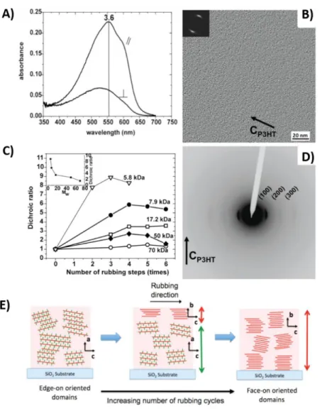
From a structural point of view, more work on the orientation of P3HT was done by Brinkmann et. al in 2011.[43] Upon rubbing, the polymer chains were aligned in the
direction of rubbing and crystals change the contact plane from edge-on to face-on with an increasing number of rubbing cycles (see figure 1.14). Polymer orientation was also studied as a function of molecular weight. A higher degree of chain orientation was observed for low molecular weight P3HT (≤ 7.9 kDa), while very poor orientation was observed for higher molecular weights (>50 kDa). The poor alignment of higher molecular weight fractions was observed due to the high degree of chain entanglement, which hindered the chain orientation. In addition to this, hole mobilities were also measured along the parallel and perpendicular directions to the rubbing for low Mw
samples. It has been observed that the mobility was enhanced along the direction parallel to the rubbing and an anisotropy (µ///µ⊥)of 20 was obtained. In most of the
studies using rubbing, alignment was performed exclusively at room temperature.[39,40]
This rubbing technique was improved later in the Brinkmann group by introducing temperature as an additional parameter. Biniek[44] et. al applied high temperature
Chapter 1: Fundamental concepts and state of the art
31
observed in C12-PBTTT by rubbing the polymer at a temperature in the range 75 °C ≤ TR
≤125 °C.[44] It has been demonstrated that temperature is an important parameter for
polymer orientation. The applied temperature helps to melt the alkyl side chains which imparts some plasticity to the film that can be easily aligned.
Figure 1.14. A) UV-Vis polarized optical absorbance spectra of an oriented P3HT thin film (17.2 kDa). Parallel and perpendicular absorbance are shown in the figure. B) & D) High-resolution TEM image and electron diffraction pattern of as-rubbed P3HT thin films (17.2 kDa). C) Evolution of the dichroic ratio for rubbed P3HT films of different molecular weights. E) Schematic illustration of edge on to face-on transformation during rubbing. All films were aligned at room temperature. Reproduced from (49)
Highly oriented films of C12-PBTTT were obtained upon rubbing at 125 °C (see figure
Chapter 1: Fundamental concepts and state of the art
32
Figure 1.15. A) UV-Vis polarized optical absorbance spectra of an oriented PBTTT thin-film rubbed at 125 °C (Parallel and perpendicular absorbance are shown in the figure). B) Evolution of the dichroic ratio as a function of the rubbing temperature (TR). C) and D) are the electron diffraction and high-resolution electron microscopy
images of oriented PBTTT rubbed at 125 °C. E) Schematic illustration of edge-on to face-on transformation during rubbing. Reproduced from (44)
The oriented films were birefringent in an optical microscope and electron diffraction patterns reveal a high degree of order along the chain direction. Because of this, the
Chapter 1: Fundamental concepts and state of the art
33
mobilities were enhanced along the rubbing direction. High-resolution TEM revealed the nanomorphology of the oriented PBTTT films. Similar to P3HT, the presence of sulphur in the oriented backbone generates a specific contrast relative to the alkyl side chain in the high-resolution images of PBTTT (see figure 1.15D). [16,19,36,45]
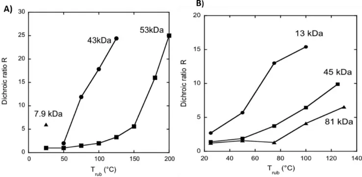
Figure 1.16. Temperature dependence of the dichroic ratio in A) P3HT and B) PBTTT for samples with different molecular weights (Mw). Reproduced from (36)
The molecular weight of a conjugated polymer is also an important parameter that influences the degree of orientation. Hence, the correlation between molecular weight and degree of alignment is an important point to discuss in this chapter. In 2014, Brinkmann and coworkers studied the effect of molecular weight on the orientation of P3HT and PBTTT batches with different molecular weights. It was observed that the lower molecular weight P3HT (13 KDa) was aligned at room temperature while the higher molecular weight (43 kDa) showed an onset of alignments at 50 °C (see figure 1.16). The P3HT batch with a molecular weight of 53 kDa was poorly oriented at low temperature and showed a high degree of alignment at higher rubbing temperature.[36]
Chapter 1: Fundamental concepts and state of the art
34
High temperature rubbing was used by Hamidi-Sakr et al. to fabricate highly oriented and crystalline films of P3HT. They were able to obtain the semi-crystalline morphology in oriented films with a very high dichroic ratio > 25.[15] Mobility measurements were
also carried out as a function of rubbing temperature on organic field-effect transistors (OFET). The mobilities along the rubbing direction were larger than those measured perpendicular to the rubbing. The measured mobilities did not improve with increasing TR because of the existence of amorphous interlamellar zones that slow down the hole
migration between crystalline domains along the rubbing direction.
Later in 2017, Hamidi-Sakr et al. showed that doping of oriented P3HT with suitable electron acceptors such as 2,3,5,6-Tetrafluoro-7,7,8,8-tetracyanoquinodimethane (F4TCNQ) produces oriented thin films with highly anisotropic electrical conductivity. In
addition, they observed that the measured conductivity was enhanced along the rubbing direction. Anisotropy in the 8-10 range was observed for the conductivity and a maximum conductivity of 22 S/cm for F4TCNQ doped P3HT along the parallel
direction.[46] High temperature rubbing was shown to be an effective method for
preparing highly oriented and crystalline polymer films with enhanced conductivity along the rubbing direction.
In the frame of my thesis, I used high-temperature rubbing to align different polythiophenes for thermoelectric applications, as discussed in chapter 2, 3 and 4.
4.2. Orientation by friction transfer
Smith and Wittmann pioneered this method of polymer orientation for oriented PTFE (Polytetrafluoroethylene) layers.[47,48] Friction transfer is a versatile method and it can
be widely applied to align a large palette of polymers including P3HT, poly(9,9′-dioctyl-fluorene) (PFO) etc.
Chapter 1: Fundamental concepts and state of the art
35
Figure 1.17. A) Schematic representation of the friction transfer deposition method. B) SEM image of an aligned P3HT film-oriented by friction transfer. C) and D) represent corresponding polarized Uv-Vis spectra along the parallel and perpendicular direction and the section profile from Grazing incidence X-ray diffraction respectively. Reproduced from(49&50)
The polymer to be aligned is first compressed in the form of a cylindrical pellet under high pressure. This pellet is translated over a hot substrate at a constant speed and a thin oriented polymer film is deposited on the hot substrate (see figure 1.17).[49]
Nagamatsu and coworkers applied this technique for the fabrication of oriented films of P3HT and poly(3-dodecylthiophene).[50] The oriented P3HT displayed an order
parameter close to unity. The distribution of in-plane orientation of P3HT chain axis is of around 10 ° as evidenced by Grazing X-ray diffraction measurements. X-ray diffraction measurements indicate that the π stacking (b axis) is perpendicular to the substrate plane and the polymer crystals adopt a face-on orientation after alignment. Poly(3-dodecyl thiophene) films oriented by friction transfer also showed high degree of
Chapter 1: Fundamental concepts and state of the art
36
orientation along the drawing direction. Mobility measurements were carried out parallel and perpendicular to the direction of rubbing in OFET devices. The measured mobilities were highly anisotropic and anisotropy factors of µ///µ⊥ =8were observed in
these films.The main disadvantage of this method is that the substrate must be heated to very high temperature and the thickness of the deposited film is difficult to control. Moreover, large amounts of polymers are necessary to prepare the pellets.
4.3. Orientation by strain alignment
Strain alignment is an alternating technique used for aligning semiconducting polymers. In this method, the active polymer is deposited on a stretchable substrate such as Polydimethylsiloxane (PDMS). After deposition, the substrate can be stretched in a specific direction and hence the crystals and polymeric chains (backbones) can be aligned in the direction of stretching.
Figure 1.18. A) Evolution of the dichroic ratio as a function of applied stress. B) Anisotropy of hole mobilities in strain aligned P3HT films in OFETs. Reproduced from (52)
Dyreklev et. al used the strain alignment method to obtain polarized electroluminescence out of a thin film of poly(3-(4-octylphenyl)-2,2′-bithiophene) (PTOPT) with a dichroic ratio of 2.4.[49,51] DeLongchamp and coworkers[52] applied strain


![Figure 1.9. Chemical structure and HOMO – LUMO energy levels of P3HT and Poly(2,5-bis(3-alkylthiophene-2- Poly(2,5-bis(3-alkylthiophene-2-yl)thieno[3,2-b]thiophene)](https://thumb-eu.123doks.com/thumbv2/123doknet/14285933.492101/38.918.267.641.515.788/figure-chemical-structure-energy-levels-alkylthiophene-alkylthiophene-thiophene.webp)