https://doi.org/10.4224/23002823
READ THESE TERMS AND CONDITIONS CAREFULLY BEFORE USING THIS WEBSITE.
https://nrc-publications.canada.ca/eng/copyright
Vous avez des questions? Nous pouvons vous aider. Pour communiquer directement avec un auteur, consultez la première page de la revue dans laquelle son article a été publié afin de trouver ses coordonnées. Si vous n’arrivez pas à les repérer, communiquez avec nous à PublicationsArchive-ArchivesPublications@nrc-cnrc.gc.ca.
Questions? Contact the NRC Publications Archive team at
PublicationsArchive-ArchivesPublications@nrc-cnrc.gc.ca. If you wish to email the authors directly, please see the first page of the publication for their contact information.
NRC Publications Archive
Archives des publications du CNRC
For the publisher’s version, please access the DOI link below./ Pour consulter la version de l’éditeur, utilisez le lien DOI ci-dessous.
Access and use of this website and the material on it are subject to the Terms and Conditions set forth at
Airborne and impact sound insulation data for cold-formed
steel-framed walls and floors
Hoeller, Christoph; Zeitler, Berndt; Sabourin, Ivan
https://publications-cnrc.canada.ca/fra/droits
L’accès à ce site Web et l’utilisation de son contenu sont assujettis aux conditions présentées dans le site LISEZ CES CONDITIONS ATTENTIVEMENT AVANT D’UTILISER CE SITE WEB.
NRC Publications Record / Notice d'Archives des publications de CNRC: https://nrc-publications.canada.ca/eng/view/object/?id=972f2840-2341-46c9-afa5-d0b9f6225420 https://publications-cnrc.canada.ca/fra/voir/objet/?id=972f2840-2341-46c9-afa5-d0b9f6225420
Airborne and Impact Sound Insulation
Data for Cold-Formed Steel-Framed
Walls and Floors
Christoph Hoeller, Berndt Zeitler, Ivan Sabourin
A1-005007.1
15 February 2018
Contents
1. Sound Insulation of CFS-Framed Walls ... 1
1.1 Overview of Tested Wall Assemblies ... 2
1.2 Detailed Test Reports ... 6
1.3 Analysis of Results for CFS-Framed Walls ... 127
1.3.1 Transmission Loss of Reference Assembly ... 127
1.3.2 Influence of Sheathing... 128
1.3.3 Influence of Cavity Insulation... 133
1.3.4 Influence of Resilient Channels ... 134
1.3.5 Influence of Stud Spacing ... 135
1.3.6 Influence of Stud Depth ... 136
1.3.7 Influence of Steel Thickness ... 137
1.3.8 Influence of Flat Straps and Bridging Channels ... 138
2. Sound Insulation of CFS-Framed Floors ... 139
2.1 Overview of Tested Floor Assemblies ... 140
2.2 Detailed Test Reports ... 145
2.3 Analysis of Results for CFS-Framed Floors – Airborne Sound Transmission ... 215
2.3.1 Transmission Loss of Reference Assembly ... 215
2.3.2 Influence of Joist Depth ... 216
2.3.3 Influence of Gypsum Board Ceiling ... 218
2.3.4 Influence of Floor Coverings ... 220
2.4 Analysis of Results for CFS-Framed Floors – Impact Sound Transmission ... 223
2.4.1 Normalized Impact Sound Pressure Level of Reference Assembly ... 223
2.4.2 Influence of Joist Depth ... 224
2.4.3 Influence of Gypsum Board Ceiling ... 226
2.4.4 Influence of Floor Coverings ... 228
REPORT A1-005007.1 ii
List of Figures
Figure 1: Transmission loss of reference wall assembly ... 127
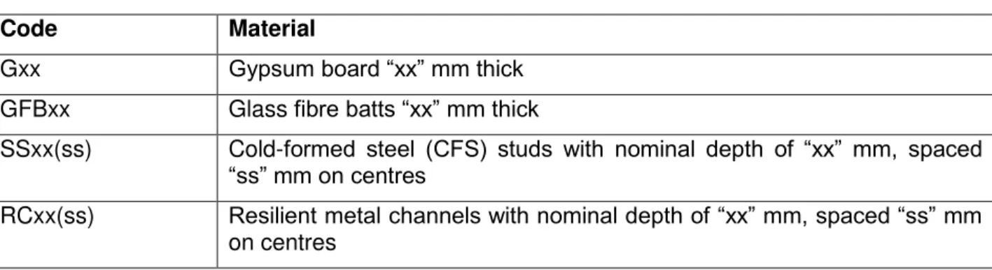
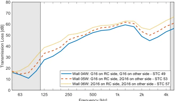
Figure 2: Influence of the layers of gypsum board on the transmission loss ... 128
Figure 3: Influence of the type of gypsum board on the coincidence frequency ... 129
Figure 4: Influence of the layers of gypsum board for walls without cavity insulation ... 130
Figure 5: Influence of the layers of gypsum board for walls without resilient channels... 131
Figure 6: Influence of the layers of gypsum board for 92 mm deep walls ... 132
Figure 7: Influence of cavity insulation ... 133
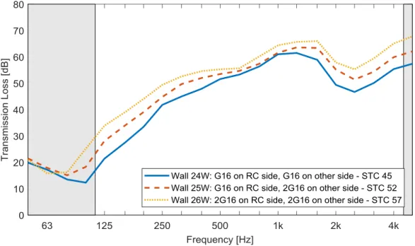
Figure 8: Influence of resilient channels ... 134
Figure 9: Influence of stud spacing ... 135
Figure 10: Influence of stud depth ... 136
Figure 11: Influence of the steel thickness of the wall studs ... 137
Figure 12: Influence of flat straps and bridging channels ... 138
Figure 13: Cross-section of the reference floor assembly, with detailed cut-out of the corrugated steel deck with gypsum concrete subfloor ... 141
Figure 14: Transmission loss of reference floor assembly ... 215
Figure 15: Influence of joist depth ... 217
Figure 16: Influence of joist depth – Change in transmission loss ... 217
Figure 17: Influence of gypsum board ceiling ... 219
Figure 18: Influence of gypsum board ceiling – Change in transmission loss ... 219
Figure 19: Influence of floor coverings ... 221
Figure 20: Influence of bonding method for vinyl covering ... 221
Figure 21: Influence of floor coverings – Change in transmission loss ... 222
Figure 22: Normalized impact sound pressure level of reference floor assembly ... 223
Figure 23: Influence of joist depth ... 225
Figure 24: Influence of joist depth – Change in normalized impact sound pressure level ... 225
Figure 25: Influence of gypsum board ceiling ... 227
Figure 26: Influence of gypsum board ceiling – Change in normalized impact sound pressure level ... 227
Figure 27: Influence of floor coverings ... 228
Figure 28: Influence of bonding method for vinyl covering ... 229 Figure 29: Influence of floor coverings – Change in normalized impact sound pressure level . 229
List of Tables
Table 1: Examples of the codes used to identify materials and describe constructions ... 2
Table 2: List of Wall Assemblies ... 3
Table 3: Examples of the codes used to identify materials and describe constructions ... 140
REPORT A1-005007.1 iv
Summary
This report presents the results of an extensive series of direct sound insulation tests of cold-formed steel-framed walls and floors.
The direct airborne sound insulation of 30 walls with cold-formed steel framing was measured in accordance with ASTM E90-09. The walls had steel studs with a depth of 92 mm (3-5/8”) or 152 mm (6”), and with a steel thickness of 1.09 mm (0.043”) or 1.37 mm (0.054”). Other parameters that were investigated included the number of layers and thickness of gypsum board, the cavity insulation, the stud spacing, and the use of resilient channels. The test results for some non-standard wall configurations that were tested for research purposes (e.g. for walls with gypsum board on one side only) are also included in this report.
The direct airborne and impact sound insulation of 17 floors with cold-formed steel framing was measured in accordance with ASTM E90-09 and ASTM E492-09, respectively. The floors had steel joists with a depth of 254 mm (10”) or 317 mm (12.5”), and with a steel thickness of 1.37 mm (0.054”). The top surface of the floor/ceiling assemblies was composed of a corrugated steel deck with poured gypsum concrete, while the bottom surface was composed of a gypsum board ceiling on resilient channels. The influence of the joist depth and the number of layers and thickness of the ceiling gypsum board was investigated, as well as the influence of several floor coverings (e.g. laminate or carpet).
The report presents the detailed specimen descriptions and specimen properties and the results from the standardized tests according to ASTM E90-09 and ASTM E492-09. Brief analyses of the parameters affecting the sound insulation of the steel-framed assemblies are provided. The tests presented in this report were part of a large research study that also included an investigation into the flanking sound transmission in cold-formed steel-framed buildings. The results of that study are described in the NRC Research Report RR-337, “Apparent Sound Insulation in Cold-Formed Steel-Framed Buildings” [1]. The NRC Research Report RR-337 also includes some of the airborne sound insulation results presented here, albeit without listing the detailed specimen descriptions and specimen properties that are provided in this report.
1. Sound Insulation of CFS-Framed Walls
The sound insulation properties of 30 cold-formed steel-framed wall assemblies for mid-rise construction were measured in the NRC Construction Wall Sound Transmission Facility, in accordance with the requirements of ASTM E90-09 [2]. The facility and the test method are described in Appendix A.
The first wall that was tested was chosen as reference assembly. It was constructed from 152 mm (6”) deep cold-formed steel studs spaced 406 mm (16”) on centres, with resilient channels on one side spaced 406 mm (16”) on centres and 152 mm (6”) thick glass fibre batts in the wall cavity. The sheathing consisted of one layer of 15.9 mm (5/8”) gypsum board type X on each side. The reference assembly achieved a Sound Transmission Class (STC) rating of 49. Based on the reference assembly described above, a parametric study was conducted to investigate the importance of various wall members. The following parameters were examined: the number of layers and thickness of gypsum board, the cavity insulation, the stud spacing and stud depth, the steel thickness of the studs, and the use of resilient channels. Some further tests were conducted to investigate the influence of flat strap bracing and bridging channels. The test results for some non-standard wall configurations that were tested for research purposes (e.g. for walls with gypsum board on one side only) are also included in this report.
This section is divided into three parts:
Section 1.1 provides a tabulated overview of the wall assemblies that were tested as part of this study. Table 2 contains short descriptions and drawings of all wall assemblies together with their measured STC rating and a reference to the page where the detailed test report can be found. Section 1.2 provides the detailed test reports which list the construction details, material properties, test conditions, and test results for each specimen.
Section 1.3 provides brief analyses of parameters affecting the sound insulation of cold-formed steel-framed wall assemblies.
REPORT A1-005007.1 2
1.1 Overview of Tested Wall Assemblies
Table 2 provides an overview of all wall assemblies that were tested as part of this study. Each row contains the specimen identifier, a sketch and a short code describing the specimen, the measured Sound Transmission Class (STC) rating of the specimen, and the page number where the detailed test report can be found.
A coding system is used in the table to avoid long descriptions of the wall constructions. Each surface layer in a wall is coded as follows:
An integer representing the number of layers of material; if the number of layers is one, the leading 1 is omitted
A sequence of letters to indicate the material in the layer (see Table 1 below) A number representing the thickness in mm of each sheet or element in the layer Underscores separating the codes for each layer
The coding system is also applied to elements that do not constitute surface layers such as joists, studs, and resilient metal channels. For such elements, the number following the letters is the depth of each element (the dimension along the axis perpendicular to the surface of the assembly) and the number in parentheses following the depth code is the separation between adjacent elements.
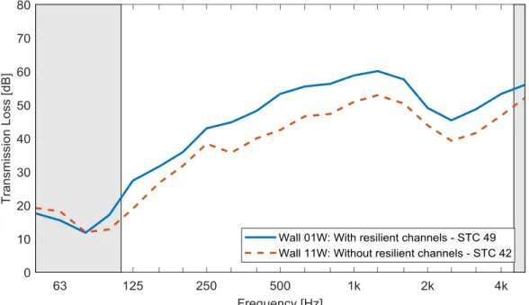
Table 1: Examples of the codes used to identify materials and describe constructions Code Material
Gxx Gypsum board “xx” mm thick
GFBxx Glass fibre batts “xx” mm thick
SSxx(ss) Cold-formed steel (CFS) studs with nominal depth of “xx” mm, spaced “ss” mm on centres
RCxx(ss) Resilient metal channels with nominal depth of “xx” mm, spaced “ss” mm
on centres
Note that the coding system is a convenience and actual dimensions may not be exactly as coded. For example, the nominal 16 mm thick gypsum board would be labelled by the manufacturer as 5/8” or 15.9 mm thick.
For brevity, not all pertinent parameters are included in the short codes. For example, the thickness of the steel in the CFS studs is not indicated. This information is given separately in the specimen descriptions in Section 1.2.
Table 2: List of Wall Assemblies
Specimen Sketch and Short Code STC Page
A1-005007-01W G16_SS152(406)_GFB152_RC13(406)_G16 49 7 A1-005007-02W 2G16_SS152(406)_GFB152_RC13(406)_2G16 58 11 A1-005007-03W 2G13_SS152(406)_GFB152_RC13(406)_2G13 57 15 A1-005007-04W G16_SS152(406)_GFB92_RC13(406)_G16 49 19 A1-005007-05W 2G16_SS152(406)_GFB92_RC13(406)_G16 53 23 A1-005007-06W 2G16_SS152(406)_GFB92_RC13(406)_2G16 57 27 A1-005007-07W G16_SS152(406)_RC13(406)_G16 42 31 A1-005007-08W 2G16_SS152(406)_RC13(406)_G16 47 35 A1-005007-09W 2G16_SS152(406)_RC13(406)_2G16 53 39 A1-005007-10W G16_SS152(406)_RC13(406)_2G16 48 43
REPORT A1-005007.1 4
Specimen Sketch and Short Code STC Page
A1-005007-11W G16_SS152(406)_GFB152_G16 42 47 A1-005007-12W G16_SS152(406)_GFB152_2G16 45 51 A1-005007-13W 2G16_SS152(406)_GFB152_2G16 48 55 A1-005007-14W G16_SS152(406)_GFB152_RC13(406)_G16 48 59 A1-005007-15W 2G16_SS152(406)_GFB152_RC13(406)_G16 54 63 A1-005007-16W 2G16_SS152(406)_GFB152_RC13(406)_2G16 57 67 A1-005007-17W SS152(406)_GFB152_RC13(406)_2G16 43 71 A1-005007-18W SS152(406)_GFB152_RC13(406)_G16 38 75 A1-005007-19W SS152(406)_GFB152_G16 37 79 A1-005007-20W G16_SS152(610)_GFB92_RC13(406)_G16 50 83
Specimen Sketch and Short Code STC Page A1-005007-21W 2G16_SS152(610)_GFB92_RC13(406)_G16 55 87 A1-005007-22W 2G16_SS152(610)_GFB92_RC13(406)_2G16 59 91 A1-005007-23W 2G16_SS152(610)_GFB152_RC13(406)_2G16 60 95 A1-005007-24W G16_SS92(406)_GFB92_RC13(406)_G16 45 99 A1-005007-25W 2G16_SS92(406)_GFB92_RC13(406)_G16 52 103 A1-005007-26W 2G16_SS92(406)_GFB92_RC13(406)_2G16 57 107 A1-005007-27W G16_SS92(406)_GFB92_G16 38 111 A1-005007-28W G16_SS152(406)_GFB152_RC13(406)_G16 50 115 A1-005007-29W 2G16_SS152(406)_GFB152_RC13(406)_G16 54 119 A1-005007-30W 2G16_SS152(406)_GFB152_RC13(406)_2G16 58 123
REPORT A1-005007.1 6
1.2 Detailed Test Reports
The following pages contain the detailed test reports for the 30 wall assemblies that were tested as part of this study. Each report presents the detailed specimen descriptions, material properties, test conditions, and test results.
Wall assembly 01W: G16_SS152(406)_GFB152_RC13(406)_G16
Description One layer of 15.9 mm (5/8”) gypsum board Type X, attached on each side of
152 mm (6”) deep steel studs spaced 406 mm (16”) o.c., with resilient channels on one side spaced 406 mm (16”) o.c. and 152 mm (6”) deep glass fibre insulation (R-20) in the cavity.
Side 1 (1) One layer of 15.9 mm (5/8”) gypsum board Type X, installed vertically,
directly attached to the studs using 32 mm (1-1/4”) screws (#6 scavenger head) spaced 305 mm (12”) o.c. at the perimeter and in the field
Joints of Side 1 gypsum boards staggered by at least one stud spacing from joints of Side 2 gypsum boards
Gaps along the joints and the perimeter of gypsum boards caulked and taped with aluminum tape
Framing & Cavity Insulation
Base track and top track (steel thickness: 1.37 mm/0.054”) attached to test frame using four 19 mm (3/4”) screws (#10 wafer head)
(2) 152 mm (6”) deep steel C-studs (steel thickness: 1.37 mm/0.054”) spaced 406 mm (16”) o.c., attached to base track and top track using 19 mm (3/4”) screws (#10 pan head)
One through-the-knockout bridging channel, attached to each stud using 140 mm (5-1/2”) bridging clips
Flat-strap steel cross-bracing, attached on Side 1 to each stud using 19 mm (3/4”) screws (#10 pan head)
(3) Cavities between studs filled with 406 mm (16”) wide by 152 mm (6”) thick glass fibre insulation (R-20), cut in half to accommodate bridging channel
Side 2 (4) 13 mm resilient channels installed horizontally using 19 mm (3/4”)
screws (#10 wafer head), spaced 406 mm (16”) o.c. and installed according to ASTM C754-11
(5) One layer of 15.9 mm (5/8”) gypsum board Type X, installed vertically, attached to resilient channels using 32 mm (1-1/4”) screws (#6 scavenger head) spaced 305 mm (12”) o.c. at the perimeter and in the field
Joints of Side 1 gypsum boards staggered by at least one stud spacing from joints of Side 2 gypsum boards
Gaps along the joints and the perimeter of gypsum boards caulked and taped with aluminum tape
REPORT A1-005007.1 8 Specimen Properties Element Actual thickness (mm)
Mass (kg) Mass/length, area or volume Gypsum Board 15.9 97.8 11.0 kg/m² Flat Strap 1 3.0 0.3 kg/m Steel Studs 152 65.0 2.7 kg/m Steel Tracks 152 * 16.6 2.3 kg/m C Channel Bridging 1 * 1.9 0.5 kg/m
Angle Bracket 1 * 10.8 1.1 kg/piece
Glass Fibre Insulation 152 * 12.4 9.2 kg/m³
Resilient Channels 13 5.6 0.2 kg/m
Gypsum Board 15.9 97.8 11.0 kg/m²
Total 197.8 310.9
For a description of the test specimen and mounting conditions see text pages before. The results in this report apply only to the specific sample submitted for measurement. No responsibility is assumed for performance of any other specimen. Airborne sound transmission loss
measurements were conducted in accordance with the requirements of ASTM E90-09, “Standard Test Method for Laboratory Measurement of Airborne Sound Transmission Loss of Building Partitions and Elements.”
In the graph:
The solid line is the measured sound transmission loss for this specimen. The dashed line is the STC contour fitted to the measured values according to ASTM E413-10. The dotted line (may be above the displayed range) is 10 dB below the flanking limit established for this facility. For any frequency band where the measured transmission loss is above the dotted line, the reported value is potentially limited by flanking transmission via laboratory surfaces, and the true value may be higher than that measured. Bars at the bottom of the graph show deficiencies where the measured data are less than the reference contour as described in the fitting procedure for the STC, defined in ASTM E413-10. The shaded cells in the table and areas in the graph are outside the STC contour range.
In the table:
Values marked “c” indicate that the measured background level was between 5 dB and 10 dB below the combined receiving room level and background level. The reported values have been corrected according to the procedure outlined in ASTM E90-09. Values marked “*” indicate that the measured background level was less than 5 dB below the combined receiving room level and background level, in which case, the corrected values provide an estimate of the lower limit of airborne sound transmission loss.
ASTM E90 Test Results
– Airborne Sound Transmission Loss
Client: CSSBI Test ID: TLA-14-041
Specimen ID: A1-005007-01W Date of Test: 15 August 2014
Room Volume (m³) Air Temperature (°C) Humidity (%)
Large 255.8 19.4 to 19.5 56.4 to 56.5 Area of test specimen: 8.92 m2
Small 140.7 19.6 to 19.7 55.5 to 56.0 Mass of test specimen: 310.9 kg
f (Hz) TL (dB) 50 18 63 16 80 12 100 17 125 27 160 32 200 36 250 43 315 45 400 48 500 53 630 56 800 56 1000 59 1250 60 1600 58 2000 49 2500 45 3150 49 4000 53 5000 56 Sound Transmission Class (STC) 49 Sum of Deficiencies (dB) 29 Max. Deficiency (dB) 8 dB at 2500 Hz 6 4 3 0 0 0 0 0 0 0 0 0 4 8 4 0 0 10 20 30 40 50 60 70 80 90 100 63 125 250 500 1000 2000 4000 Ai rb o rn e So u n d T ra n s m is s io n L o s s , T L , in d B Frequency, f, in Hz STC 49
REPORT A1-005007.1 10
Wall assembly 02W: 2G16_SS152(406)_GFB152_RC13(406)_2G16
Description Two layers of 15.9 mm (5/8”) gypsum board Type X, attached on each side of
152 mm (6”) deep steel studs spaced 406 mm (16”) o.c., with resilient channels on one side spaced 406 mm (16”) o.c. and 152 mm (6”) deep glass fibre insulation (R-20) in the cavity.
Side 1 Two layers of 15.9 mm (5/8”) gypsum board Type X, installed vertically
(2) Base layer attached to the studs using 32 mm (1-1/4”) screws (#6 scavenger head) spaced 305 mm (12”) o.c. at the perimeter and in the field
(1) Face layer attached to base layer and studs using 41 mm (1-5/8”) screws (#6 scavenger head) spaced 305 mm (12”) o.c. at the perimeter and in the field
Screws from base layer to face layer offset by 152 mm (6”)
Joints of base layer Side 1 gypsum boards staggered by at least one stud spacing from joints of base layer Side 2 gypsum boards
Joints of face layer staggered by at least one stud spacing from joints of base layer
Gaps along the joints and the perimeter of face layer gypsum boards caulked and taped with aluminum tape
Framing & Cavity Insulation
Base track and top track (steel thickness: 1.37 mm/0.054”) attached to test frame using four 19 mm (3/4”) screws (#10 wafer head)
(3) 152 mm (6”) deep steel C-studs (steel thickness: 1.37 mm/0.054”) spaced 406 mm (16”) o.c., attached to base track and top track using 19 mm (3/4”) screws (#10 pan head)
One through-the-knockout bridging channel, attached to each stud using 140 mm (5-1/2”) bridging clips
Flat-strap steel cross-bracing, attached on Side 1 to each stud using 19 mm (3/4”) screws (#10 pan head)
(4) Cavities between studs filled with 406 mm (16”) wide by 152 mm (6”) thick glass fibre insulation (R-20), cut in half to accommodate bridging channel
Side 2 (5) 13 mm resilient channels installed horizontally using 19 mm (3/4”)
screws (#10 wafer head), spaced 406 mm (16”) o.c. and installed according to ASTM C754-11
REPORT A1-005007.1 12
(6) Base layer attached to resilient channels using 32 mm (1-1/4”) screws (#6 scavenger head) spaced 305 mm (12”) o.c. at the perimeter and in the field
(7) Face layer attached to base layer and resilient channels using 41 mm (1-5/8”) screws (#6 scavenger head) spaced 305 mm (12”) o.c. at the perimeter and in the field
Screws from base layer to face layer offset by 152 mm (6”)
Joints of base layer Side 1 gypsum boards staggered by at least one stud spacing from joints of base layer Side 2 gypsum boards
Joints of face layer staggered by at least one stud spacing from joints of base layer
Gaps along the joints and the perimeter of face layer gypsum boards caulked and taped with aluminum tape
Specimen Properties
Element
Actual thickness
(mm)
Mass (kg) Mass/length, area or volume Gypsum Board 15.9 97.8 11.0 kg/m² Gypsum Board 15.9 97.8 11.0 kg/m² Flat Strap 1 3.0 0.3 kg/m Steel Studs 152 65.0 2.7 kg/m Steel Tracks 152 * 16.6 2.3 kg/m C Channel Bridging 1 * 1.9 0.5 kg/m
Angle Bracket 1 * 10.8 1.1 kg/piece
Glass Fibre Insulation 152 * 12.4 9.2 kg/m³
Resilient Channels 13 5.6 0.2 kg/m
Gypsum Board 15.9 97.8 11.0 kg/m²
Gypsum Board 15.9 97.8 11.0 kg/m²
Total 229.6 506.5
For a description of the test specimen and mounting conditions see text pages before. The results in this report apply only to the specific sample submitted for measurement. No responsibility is assumed for performance of any other specimen. Airborne sound transmission loss
measurements were conducted in accordance with the requirements of ASTM E90-09, “Standard Test Method for Laboratory Measurement of Airborne Sound Transmission Loss of Building Partitions and Elements.”
In the graph:
The solid line is the measured sound transmission loss for this specimen. The dashed line is the STC contour fitted to the measured values according to ASTM E413-10. The dotted line (may be above the displayed range) is 10 dB below the flanking limit established for this facility. For any frequency band where the measured transmission loss is above the dotted line, the reported value is potentially limited by flanking transmission via laboratory surfaces, and the true value may be higher than that measured. Bars at the bottom of the graph show deficiencies where the measured data are less than the reference contour as described in the fitting procedure for the STC, defined in ASTM E413-10. The shaded cells in the table and areas in the graph are outside the STC contour range.
In the table:
Values marked “c” indicate that the measured background level was between 5 dB and 10 dB below the combined receiving room level and background level. The reported values have been corrected according to the procedure outlined in ASTM E90-09. Values marked “*” indicate that the measured background level was less than 5 dB below the combined receiving room level and background level, in which case, the corrected values provide an estimate of the lower limit of airborne sound transmission loss.
ASTM E90 Test Results
– Airborne Sound Transmission Loss
Client: CSSBI Test ID: TLA-14-042
Specimen ID: A1-005007-02W Date of Test: 15 August 2014
Room Volume (m³) Air Temperature (°C) Humidity (%)
Large 255.6 19.7 to 19.8 54.4 to 55.2 Area of test specimen: 8.92 m2
Small 140.6 19.8 to 19.9 55.4 to 56.3 Mass of test specimen: 506.5 kg
f (Hz) TL (dB) 50 17 63 18 80 22 100 30 125 38 160 43 200 45 250 50 315 52 400 54 500 58 630 60 800 60 1000 61 1250 63 1600 62 2000 55 2500 55 3150 59 4000 63 5000 66 Sound Transmission Class (STC) 58 Sum of Deficiencies (dB) 32 Max. Deficiency (dB) 7 dB at 2000 Hz and 2500 Hz 4 2 3 1 2 3 0 0 0 0 0 0 7 7 3 0 0 10 20 30 40 50 60 70 80 90 100 63 125 250 500 1000 2000 4000 Ai rb o rn e So u n d T ra n s m is s io n L o s s , T L , in d B Frequency, f, in Hz STC 58
REPORT A1-005007.1 14
Wall assembly 03W: 2G13_SS152(406)_GFB152_RC13(406)_2G13
Description Two layers of 12.7 mm (1/2”) gypsum board Firecode C Type X, attached on
each side of 152 mm (6”) deep steel studs spaced 406 mm (16”) o.c., with resilient channels on one side spaced 406 mm (16”) o.c. and 152 mm (6”) deep glass fibre insulation (R-20) in the cavity.
Side 1 Two layers of 12.7 mm (1/2”) gypsum board Firecode C Type X, installed
vertically
(2) Base layer attached to the studs using 32 mm (1-1/4”) screws (#6 scavenger head) spaced 305 mm (12”) o.c. at the perimeter and in the field
(1) Face layer attached to base layer and studs using 41 mm (1-5/8”) screws (#6 scavenger head) spaced 305 mm (12”) o.c. at the perimeter and in the field
Screws from base layer to face layer offset by 152 mm (6”)
Joints of base layer Side 1 gypsum boards staggered by at least one stud spacing from joints of base layer Side 2 gypsum boards
Joints of face layer staggered by at least one stud spacing from joints of base layer
Gaps along the joints and the perimeter of face layer gypsum boards caulked and taped with aluminum tape
Framing & Cavity Insulation
Base track and top track (steel thickness: 1.37 mm/0.054”) attached to test frame using four 19 mm (3/4”) screws (#10 wafer head)
(3) 152 mm (6”) deep steel C-studs (steel thickness: 1.37 mm/0.054”) spaced 406 mm (16”) o.c., attached to base track and top track using 19 mm (3/4”) screws (#10 pan head)
One through-the-knockout bridging channel, attached to each stud using 140 mm (5-1/2”) bridging clips
Flat-strap steel cross-bracing, attached on Side 1 to each stud using 19 mm (3/4”) screws (#10 pan head)
(4) Cavities between studs filled with 406 mm (16”) wide by 152 mm (6”) thick glass fibre insulation (R-20), cut in half to accommodate bridging channel
Side 2 (5) 13 mm resilient channels installed horizontally using 19 mm (3/4”)
screws (#10 wafer head), spaced 406 mm (16”) o.c. and installed according to ASTM C754-11
REPORT A1-005007.1 16
Two layers of 12.7 mm (1/2”) gypsum board Firecode C Type X, installed vertically
(6) Base layer attached to resilient channels using 32 mm (1-1/4”) screws (#6 scavenger head) spaced 305 mm (12”) o.c. at the perimeter and in the field
(7) Face layer attached to base layer and resilient channels using 41 mm (1-5/8”) screws (#6 scavenger head) spaced 305 mm (12”) o.c. at the perimeter and in the field
Screws from base layer to face layer offset by 152 mm (6”)
Joints of base layer Side 1 gypsum boards staggered by at least one stud spacing from joints of base layer Side 2 gypsum boards
Joints of face layer staggered by at least one stud spacing from joints of base layer
Gaps along the joints and the perimeter of face layer gypsum boards caulked and taped with aluminum tape
Specimen Properties
Element
Actual thickness
(mm)
Mass (kg) Mass/length, area or volume Gypsum Board 12.7 89.4 10.0 kg/m² Gypsum Board 12.7 89.4 10.0 kg/m² Flat Strap 1 3.0 0.3 kg/m Steel Studs 152 65.0 2.7 kg/m Steel Tracks 152 * 16.6 2.3 kg/m C Channel Bridging 1 * 1.9 0.5 kg/m
Angle Bracket 1 * 10.8 1.1 kg/piece
Glass Fibre Insulation 152 * 12.4 9.2 kg/m³
Resilient Channels 13 5.6 0.2 kg/m
Gypsum Board 12.7 89.4 10.0 kg/m²
Gypsum Board 12.7 89.4 10.0 kg/m²
Total 216.8 472.9
For a description of the test specimen and mounting conditions see text pages before. The results in this report apply only to the specific sample submitted for measurement. No responsibility is assumed for performance of any other specimen. Airborne sound transmission loss
measurements were conducted in accordance with the requirements of ASTM E90-09, “Standard Test Method for Laboratory Measurement of Airborne Sound Transmission Loss of Building Partitions and Elements.”
In the graph:
The solid line is the measured sound transmission loss for this specimen. The dashed line is the STC contour fitted to the measured values according to ASTM E413-10. The dotted line (may be above the displayed range) is 10 dB below the flanking limit established for this facility. For any frequency band where the measured transmission loss is above the dotted line, the reported value is potentially limited by flanking transmission via laboratory surfaces, and the true value may be higher than that measured. Bars at the bottom of the graph show deficiencies where the measured data are less than the reference contour as described in the fitting procedure for the STC, defined in ASTM E413-10. The shaded cells in the table and areas in the graph are outside the STC contour range.
In the table:
Values marked “c” indicate that the measured background level was between 5 dB and 10 dB below the combined receiving room level and background level. The reported values have been corrected according to the procedure outlined in ASTM E90-09. Values marked “*” indicate that the measured background level was less than 5 dB below the combined receiving room level and background level, in which case, the corrected values provide an estimate of the lower limit of airborne sound transmission loss.
ASTM E90 Test Results
– Airborne Sound Transmission Loss
Client: CSSBI Test ID: TLA-14-043
Specimen ID: A1-005007-03W Date of Test: 18 August 2014
Room Volume (m³) Air Temperature (°C) Humidity (%)
Large 255.7 19.9 to 20.0 53.3 to 54.3 Area of test specimen: 8.92 m2
Small 140.6 20.0 to 20.1 59.0 to 59.3 Mass of test specimen: 472.9 kg
f (Hz) TL (dB) 50 17 63 16 80 19 100 27 125 36 160 41 200 45 250 50 315 51 400 54 500 57 630 59 800 59 1000 61 1250 63 1600 64 2000 62 2500 55 3150 57 4000 62 5000 65 Sound Transmission Class (STC) 57 Sum of Deficiencies (dB) 24 Max. Deficiency (dB) 6 dB at 2500 Hz 5 3 2 0 2 2 0 0 0 0 0 0 0 6 4 0 0 10 20 30 40 50 60 70 80 90 100 63 125 250 500 1000 2000 4000 Ai rb o rn e So u n d T ra n s m is s io n L o s s , T L , in d B Frequency, f, in Hz STC 57
REPORT A1-005007.1 18
Wall assembly 04W: G16_SS152(406)_GFB92_RC13(406)_G16
Description One layer of 15.9 mm (5/8”) gypsum board Type X, attached on each side of
152 mm (6”) deep steel studs spaced 406 mm (16”) o.c., with resilient channels on one side spaced 406 mm (16”) o.c. and 92 mm (3-5/8”) deep glass fibre insulation (R-12) in the cavity.
Side 1 (1) One layer of 15.9 mm (5/8”) gypsum board Type X, installed vertically
and directly attached to the studs using 32 mm (1-1/4”) screws (#6 scavenger head) spaced 305 mm (12”) o.c. at the perimeter and in the field
Joints of Side 1 gypsum boards staggered by at least one stud spacing from joints of Side 2 gypsum boards
Gaps along the joints and the perimeter of gypsum boards caulked and taped with aluminum tape
Framing & Cavity Insulation
Base track and top track (steel thickness: 1.37 mm/0.054”) attached to test frame using four 19 mm (3/4”) screws (#10 wafer head)
(2) 152 mm (6”) deep steel C-studs (steel thickness: 1.37 mm/0.054”) spaced 406 mm (16”) o.c., attached to base track and top track using 19 mm (3/4”) screws (#10 pan head)
One through-the-knockout bridging channel, attached to each stud using 140 mm (5-1/2”) bridging clips
Flat-strap steel cross-bracing, attached on Side 1 to each stud using 19 mm (3/4”) screws (#10 pan head)
(3) Cavities between studs filled with 406 mm (16”) wide by 92 mm (3-5/8”) thick glass fibre insulation (R-12), cut in half to accommodate bridging channel
Side 2 (4) 13 mm resilient channels installed horizontally using 19 mm (3/4”)
screws (#10 wafer head), spaced 406 mm (16”) o.c. and installed according to ASTM C754-11
(5) One layer of 15.9 mm (5/8”) gypsum board Type X, installed vertically, attached to resilient channels using 32 mm (1-1/4”) screws (#6 scavenger head) spaced 305 mm (12”) o.c. at the perimeter and in the field
Joints of Side 1 gypsum boards staggered by at least one stud spacing from joints of Side 2 gypsum boards
Gaps along the joints and the perimeter of gypsum boards caulked and taped with aluminum tape
REPORT A1-005007.1 20 Specimen Properties Element Actual thickness (mm)
Mass (kg) Mass/length, area or volume Gypsum Board 15.9 97.8 11.0 kg/m² Flat Strap 1 3.0 0.3 kg/m Steel Studs 152 65.0 2.7 kg/m Steel Tracks 152 * 16.6 2.3 kg/m C Channel Bridging 1 * 1.9 0.5 kg/m
Angle Bracket 1 * 10.8 1.1 kg/piece
Glass Fibre Insulation 92 * 8.5 10.4 kg/m³
Resilient Channels 13 5.6 0.2 kg/m
Gypsum Board 15.9 97.8 11.0 kg/m²
Total 197.8 307.0
For a description of the test specimen and mounting conditions see text pages before. The results in this report apply only to the specific sample submitted for measurement. No responsibility is assumed for performance of any other specimen. Airborne sound transmission loss
measurements were conducted in accordance with the requirements of ASTM E90-09, “Standard Test Method for Laboratory Measurement of Airborne Sound Transmission Loss of Building Partitions and Elements.”
In the graph:
The solid line is the measured sound transmission loss for this specimen. The dashed line is the STC contour fitted to the measured values according to ASTM E413-10. The dotted line (may be above the displayed range) is 10 dB below the flanking limit established for this facility. For any frequency band where the measured transmission loss is above the dotted line, the reported value is potentially limited by flanking transmission via laboratory surfaces, and the true value may be higher than that measured. Bars at the bottom of the graph show deficiencies where the measured data are less than the reference contour as described in the fitting procedure for the STC, defined in ASTM E413-10. The shaded cells in the table and areas in the graph are outside the STC contour range.
In the table:
Values marked “c” indicate that the measured background level was between 5 dB and 10 dB below the combined receiving room level and background level. The reported values have been corrected according to the procedure outlined in ASTM E90-09. Values marked “*” indicate that the measured background level was less than 5 dB below the combined receiving room level and background level, in which case, the corrected values provide an estimate of the lower limit of airborne sound transmission loss.
ASTM E90 Test Results
– Airborne Sound Transmission Loss
Client: CSSBI Test ID: TLA-14-044
Specimen ID: A1-005007-04W Date of Test: 19 August 2014
Room Volume (m³) Air Temperature (°C) Humidity (%)
Large 255.7 20.1 to 20.1 55.7 to 56.1 Area of test specimen: 8.92 m2
Small 140.7 20.1 to 20.2 57.7 to 58.4 Mass of test specimen: 307.0 kg
f (Hz) TL (dB) 50 16 63 14 80 11 100 18 125 28 160 31 200 35 250 42 315 45 400 49 500 52 630 54 800 55 1000 57 1250 59 1600 16 2000 49 2500 45 3150 48 4000 53 5000 56 Sound Transmission Class (STC) 49 Sum of Deficiencies (dB) 31 Max. Deficiency (dB) 8 dB at 2500 Hz 5 5 4 0 0 0 0 0 0 0 0 0 4 8 5 0 0 10 20 30 40 50 60 70 80 90 100 63 125 250 500 1000 2000 4000 Ai rb o rn e So u n d T ra n s m is s io n L o s s , T L , in d B Frequency, f, in Hz STC 49
REPORT A1-005007.1 22
Wall assembly 05W: 2G16_SS152(406)_GFB92_RC13(406)_G16
Description Two layers of 15.9 mm (5/8”) gypsum board Type X, directly attached to one
side of 152 mm (6”) deep steel studs spaced 406 mm (16”) o.c., and one layer of 15.9 mm (5/8”) gypsum board Type X attached to resilient channels spaced 406 mm (16”) o.c. on the other side, with 92 mm (3-5/8”) deep glass fibre insulation (R-12) in the cavity.
Side 1 Two layers of 15.9 mm (5/8”) gypsum board Type X, installed vertically
(2) Base layer attached to the studs using 32 mm (1-1/4”) screws (#6 scavenger head) spaced 305 mm (12”) o.c. at the perimeter and in the field
(1) Face layer attached to base layer and studs using 41 mm (1-5/8”) screws (#6 scavenger head) spaced 305 mm (12”) o.c. at the perimeter and in the field
Screws from base layer to face layer offset by 152 mm (6”)
Joints of base layer Side 1 gypsum boards staggered by at least one stud spacing from joints of base layer Side 2 gypsum boards
Joints of face layer staggered by at least one stud spacing from joints of base layer
Gaps along the joints and the perimeter of face layer gypsum boards caulked and taped with aluminum tape
Framing & Cavity Insulation
Base track and top track (steel thickness: 1.37 mm/0.054”) attached to test frame using four 19 mm (3/4”) screws (#10 wafer head)
(3) 152 mm (6”) deep steel C-studs (steel thickness: 1.37 mm/0.054”) spaced 406 mm (16”) o.c., attached to base track and top track using 19 mm (3/4”) screws (#10 pan head)
One through-the-knockout bridging channel, attached to each stud using 140 mm (5-1/2”) bridging clips
Flat-strap steel cross-bracing, attached on Side 1 to each stud using 19 mm (3/4”) screws (#10 pan head)
(4) Cavities between studs filled with 406 mm (16”) wide by 92 mm (3-5/8”) thick glass fibre insulation (R-12), cut in half to accommodate bridging channel
Side 2 (5) 13 mm resilient channels installed horizontally using 19 mm (3/4”)
screws (#10 wafer head), spaced 406 mm (16”) o.c. and installed according to ASTM C754-11
REPORT A1-005007.1 24
(6) One layer of 15.9 mm (5/8”) gypsum board Type X, installed vertically and attached to resilient channels using 32 mm (1-1/4”) screws (#6 scavenger head) spaced 305 mm (12”) o.c. at the perimeter and in the field
Joints of Side 1 gypsum boards staggered by at least one stud spacing from joints of Side 2 gypsum boards
Gaps along the joints and the perimeter of gypsum boards caulked and taped with aluminum tape
Specimen Properties
Element
Actual thickness
(mm)
Mass (kg) Mass/length, area or volume Gypsum Board 15.9 97.8 11.0 kg/m² Gypsum Board 15.9 97.8 11.0 kg/m² Flat Strap 1 3.0 0.3 kg/m Steel Studs 152 65.0 2.7 kg/m Steel Tracks 152 * 16.6 2.3 kg/m C Channel Bridging 1 * 1.9 0.5 kg/m
Angle Bracket 1 * 10.8 1.1 kg/piece
Glass Fibre Insulation 92 * 8.5 10.4 kg/m³
Resilient Channels 13 5.6 0.2 kg/m
Gypsum Board 15.9 97.8 11.0 kg/m²
Total 213.7 404.8
For a description of the test specimen and mounting conditions see text pages before. The results in this report apply only to the specific sample submitted for measurement. No responsibility is assumed for performance of any other specimen. Airborne sound transmission loss
measurements were conducted in accordance with the requirements of ASTM E90-09, “Standard Test Method for Laboratory Measurement of Airborne Sound Transmission Loss of Building Partitions and Elements.”
In the graph:
The solid line is the measured sound transmission loss for this specimen. The dashed line is the STC contour fitted to the measured values according to ASTM E413-10. The dotted line (may be above the displayed range) is 10 dB below the flanking limit established for this facility. For any frequency band where the measured transmission loss is above the dotted line, the reported value is potentially limited by flanking transmission via laboratory surfaces, and the true value may be higher than that measured. Bars at the bottom of the graph show deficiencies where the measured data are less than the reference contour as described in the fitting procedure for the STC, defined in ASTM E413-10. The shaded cells in the table and areas in the graph are outside the STC contour range.
In the table:
Values marked “c” indicate that the measured background level was between 5 dB and 10 dB below the combined receiving room level and background level. The reported values have been corrected according to the procedure outlined in ASTM E90-09. Values marked “*” indicate that the measured background level was less than 5 dB below the combined receiving room level and background level, in which case, the corrected values provide an estimate of the lower limit of airborne sound transmission loss.
ASTM E90 Test Results
– Airborne Sound Transmission Loss
Client: CSSBI Test ID: TLA-14-045
Specimen ID: A1-005007-05W Date of Test: 27 August 2014
Room Volume (m³) Air Temperature (°C) Humidity (%)
Large 255.7 20.3 to 20.3 64.7 to 65.0 Area of test specimen: 8.92 m2
Small 140.6 19.8 to 19.9 64.4 to 64.9 Mass of test specimen: 404.8 kg
f (Hz) TL (dB) 50 17 63 15 80 16 100 24 125 33 160 36 200 39 250 46 315 48 400 50 500 54 630 57 800 57 1000 59 1250 62 1600 60 2000 53 2500 50 3150 53 4000 58 5000 61 Sound Transmission Class (STC) 53 Sum of Deficiencies (dB) 30 Max. Deficiency (dB) 7 dB at 2500 Hz 4 4 4 0 1 2 0 0 0 0 0 0 4 7 4 0 0 10 20 30 40 50 60 70 80 90 100 63 125 250 500 1000 2000 4000 Ai rb o rn e So u n d T ra n s m is s io n L o s s , T L , in d B Frequency, f, in Hz STC 53
REPORT A1-005007.1 26
Wall assembly 06W: 2G16_SS152(406)_GFB92_RC13(406)_2G16
Description Two layers of 15.9 mm (5/8”) gypsum board Type X, attached on each side of
152 mm (6”) deep steel studs spaced 406 mm (16”) o.c., with resilient channels on one side spaced 406 mm (16”) o.c. and 92 mm (3-5/8”) deep glass fibre insulation (R-12) in the cavity.
Side 1 Two layers of 15.9 mm (5/8”) gypsum board Type X, installed vertically
(2) Base layer attached to the studs using 32 mm (1-1/4”) screws (#6 scavenger head) spaced 305 mm (12”) o.c. at the perimeter and in the field
(1) Face layer attached to base layer and studs using 41 mm (1-5/8”) screws (#6 scavenger head) spaced 305 mm (12”) o.c. at the perimeter and in the field
Screws from base layer to face layer offset by 152 mm (6”)
Joints of base layer Side 1 gypsum boards staggered by at least one stud spacing from joints of base layer Side 2 gypsum boards
Joints of face layer staggered by at least one stud spacing from joints of base layer
Gaps along the joints and the perimeter of face layer gypsum boards caulked and taped with aluminum tape
Framing & Cavity Insulation
Base track and top track (steel thickness: 1.37 mm/0.054”) attached to test frame using four 19 mm (3/4”) screws (#10 wafer head)
(3) 152 mm (6”) deep steel C-studs (steel thickness: 1.37 mm/0.054”) spaced 406 mm (16”) o.c., attached to base track and top track using 19 mm (3/4”) screws (#10 pan head)
One through-the-knockout bridging channel, attached to each stud using 140 mm (5-1/2”) bridging clips
Flat-strap steel cross-bracing, attached on Side 1 to each stud using 19 mm (3/4”) screws (#10 pan head)
(4) Cavities between studs filled with 406 mm (16”) wide by 92 mm (3-5/8”) thick glass fibre insulation (R-12), cut in half to accommodate bridging channel
Side 2 (5) 13 mm resilient channels installed horizontally using 19 mm (3/4”)
screws (#10 wafer head), spaced 406 mm (16”) o.c. and installed according to ASTM C754-11
REPORT A1-005007.1 28
(6) Base layer attached to resilient channels using 32 mm (1-1/4”) screws (#6 scavenger head) spaced 305 mm (12”) o.c. at the perimeter and in the field
(7) Face layer attached to base layer and resilient channels using 41 mm (1-5/8”) screws (#6 scavenger head) spaced 305 mm (12”) o.c. at the perimeter and in the field
Screws from base layer to face layer offset by 152 mm (6”)
Joints of base layer Side 1 gypsum boards staggered by at least one stud spacing from joints of base layer Side 2 gypsum boards
Joints of face layer staggered by at least one stud spacing from joints of base layer
Gaps along the joints and the perimeter of face layer gypsum boards caulked and taped with aluminum tape
Specimen Properties
Element
Actual thickness
(mm)
Mass (kg) Mass/length, area or volume Gypsum Board 15.9 97.8 11.0 kg/m² Gypsum Board 15.9 97.8 11.0 kg/m² Flat Strap 1 3.0 0.3 kg/m Steel Studs 152 65.0 2.7 kg/m Steel Tracks 152 * 16.6 2.3 kg/m C Channel Bridging 1 * 1.9 0.5 kg/m
Angle Bracket 1 * 10.8 1.1 kg/piece
Glass Fibre Insulation 92 * 8.5 10.4 kg/m³
Resilient Channels 13 5.6 0.2 kg/m
Gypsum Board 15.9 97.8 11.0 kg/m²
Gypsum Board 15.9 97.8 11.0 kg/m²
Total 229.6 502.6
For a description of the test specimen and mounting conditions see text pages before. The results in this report apply only to the specific sample submitted for measurement. No responsibility is assumed for performance of any other specimen. Airborne sound transmission loss
measurements were conducted in accordance with the requirements of ASTM E90-09, “Standard Test Method for Laboratory Measurement of Airborne Sound Transmission Loss of Building Partitions and Elements.”
In the graph:
The solid line is the measured sound transmission loss for this specimen. The dashed line is the STC contour fitted to the measured values according to ASTM E413-10. The dotted line (may be above the displayed range) is 10 dB below the flanking limit established for this facility. For any frequency band where the measured transmission loss is above the dotted line, the reported value is potentially limited by flanking transmission via laboratory surfaces, and the true value may be higher than that measured. Bars at the bottom of the graph show deficiencies where the measured data are less than the reference contour as described in the fitting procedure for the STC, defined in ASTM E413-10. The shaded cells in the table and areas in the graph are outside the STC contour range.
In the table:
Values marked “c” indicate that the measured background level was between 5 dB and 10 dB below the combined receiving room level and background level. The reported values have been corrected according to the procedure outlined in ASTM E90-09. Values marked “*” indicate that the measured background level was less than 5 dB below the combined receiving room level and background level, in which case, the corrected values provide an estimate of the lower limit of airborne sound transmission loss.
ASTM E90 Test Results
– Airborne Sound Transmission Loss
Client: CSSBI Test ID: TLA-14-046
Specimen ID: A1-005007-06W Date of Test: 28 August 2014
Room Volume (m³) Air Temperature (°C) Humidity (%)
Large 255.6 20.2 to 20.3 62.7 to 64.1 Area of test specimen: 8.92 m2
Small 140.6 20.1 to 20.1 64.0 to 64.4 Mass of test specimen: 502.6 kg
f (Hz) TL (dB) 50 16 63 18 80 22 100 31 125 39 160 42 200 45 250 50 315 51 400 53 500 57 630 59 800 59 1000 60 1250 63 1600 63 2000 57 2500 55 3150 59 4000 63 5000 67 Sound Transmission Class (STC) 57 Sum of Deficiencies (dB) 23 Max. Deficiency (dB) 6 dB at 2500 Hz 2 2 2 0 2 3 0 0 0 0 0 0 4 6 2 0 0 10 20 30 40 50 60 70 80 90 100 63 125 250 500 1000 2000 4000 Ai rb o rn e So u n d T ra n s m is s io n L o s s , T L , in d B Frequency, f, in Hz STC 57
REPORT A1-005007.1 30
Wall assembly 07W: G16_SS152(406)_RC13(406)_G16
Description One layer of 15.9 mm (5/8”) gypsum board Type X, attached on each side of
152 mm (6”) deep steel studs spaced 406 mm (16”) o.c., with resilient channels on one side spaced 406 mm (16”) o.c.
Side 1 (1) One layer of 15.9 mm (5/8”) gypsum board Type X, installed vertically
and directly attached to the studs using 32 mm (1-1/4”) screws (#6 scavenger head) spaced 305 mm (12”) o.c. at the perimeter and in the field
Joints of Side 1 gypsum boards staggered by at least one stud spacing from joints of Side 2 gypsum boards
Gaps along the joints and the perimeter of gypsum boards caulked and taped with aluminum tape
Framing & Cavity Insulation
Base track and top track (steel thickness: 1.37 mm/0.054”) attached to test frame using four 19 mm (3/4”) screws (#10 wafer head)
(2) 152 mm (6”) deep steel C-studs (steel thickness: 1.37 mm/0.054”) spaced 406 mm (16”) o.c., attached to base track and top track using 19 mm (3/4”) screws (#10 pan head)
One through-the-knockout bridging channel, attached to each stud using 140 mm (5-1/2”) bridging clips
Flat-strap steel cross-bracing, attached on Side 1 to each stud using 19 mm (3/4”) screws (#10 pan head)
Side 2 (3) 13 mm resilient channels installed horizontally using 19 mm (3/4”)
screws (#10 wafer head), spaced 406 mm (16”) o.c. and installed according to ASTM C754-11
(4) One layer of 15.9 mm (5/8”) gypsum board Type X, installed vertically attached to the resilient channels using 32 mm (1-1/4”) screws (#6 scavenger head) spaced 305 mm (12”) o.c. at the perimeter and in the field
Joints of Side 1 gypsum boards staggered by at least one stud spacing from joints of Side 2 gypsum boards
Gaps along the joints and the perimeter of gypsum boards caulked and taped with aluminum tape
REPORT A1-005007.1 32 Specimen Properties Element Actual thickness (mm)
Mass (kg) Mass/length, area or volume Gypsum Board 15.9 97.8 11.0 kg/m² Flat Strap 1 3.0 0.3 kg/m Steel Studs 152 65.0 2.7 kg/m Steel Tracks 152 * 16.6 2.3 kg/m C Channel Bridging 1 * 1.9 0.5 kg/m
Angle Bracket 1 * 10.8 1.1 kg/piece
Resilient Channels 13 5.6 0.2 kg/m
Gypsum Board 15.9 97.8 11.0 kg/m²
Total 197.8 298.5
For a description of the test specimen and mounting conditions see text pages before. The results in this report apply only to the specific sample submitted for measurement. No responsibility is assumed for performance of any other specimen. Airborne sound transmission loss
measurements were conducted in accordance with the requirements of ASTM E90-09, “Standard Test Method for Laboratory Measurement of Airborne Sound Transmission Loss of Building Partitions and Elements.”
In the graph:
The solid line is the measured sound transmission loss for this specimen. The dashed line is the STC contour fitted to the measured values according to ASTM E413-10. The dotted line (may be above the displayed range) is 10 dB below the flanking limit established for this facility. For any frequency band where the measured transmission loss is above the dotted line, the reported value is potentially limited by flanking transmission via laboratory surfaces, and the true value may be higher than that measured. Bars at the bottom of the graph show deficiencies where the measured data are less than the reference contour as described in the fitting procedure for the STC, defined in ASTM E413-10. The shaded cells in the table and areas in the graph are outside the STC contour range.
In the table:
Values marked “c” indicate that the measured background level was between 5 dB and 10 dB below the combined receiving room level and background level. The reported values have been corrected according to the procedure outlined in ASTM E90-09. Values marked “*” indicate that the measured background level was less than 5 dB below the combined receiving room level and background level, in which case, the corrected values provide an estimate of the lower limit of airborne sound transmission loss.
ASTM E90 Test Results
– Airborne Sound Transmission Loss
Client: CSSBI Test ID: TLA-14-047
Specimen ID: A1-005007-07W Date of Test: 29 August 2014
Room Volume (m³) Air Temperature (°C) Humidity (%)
Large 255.8 20.1 to 20.2 59.4 to 60.0 Area of test specimen: 8.92 m2
Small 140.7 19.9 to 20.0 59.5 to 59.8 Mass of test specimen: 298.5 kg
f (Hz) TL (dB) 50 16 63 13 80 9 100 14 125 21 160 23 200 29 250 35 315 37 400 39 500 43 630 48 800 50 1000 51 1250 53 1600 52 2000 44 2500 39 3150 45 4000 50 5000 54 Sound Transmission Class (STC) 42 Sum of Deficiencies (dB) 27 Max. Deficiency (dB) 7 dB at 2500 Hz 5 6 3 0 1 2 0 0 0 0 0 0 2 7 1 0 0 10 20 30 40 50 60 70 80 90 100 63 125 250 500 1000 2000 4000 Ai rb o rn e So u n d T ra n s m is s io n L o s s , T L , in d B Frequency, f, in Hz STC 42
REPORT A1-005007.1 34
Wall assembly 08W: 2G16_SS152(406)_RC13(406)_G16
Description Two layers of 15.9 mm (5/8”) gypsum board Type X, directly attached to one
side of 152 mm (6”) deep steel studs spaced 406 mm (16”) o.c., and one layer of 15.9 mm (5/8”) gypsum board Type X attached to resilient channels spaced 406 mm (16”) o.c. on the other side.
Side 1 Two layers of 15.9 mm (5/8”) gypsum board Type X, installed vertically
(2) Base layer attached to the studs using 32 mm (1-1/4”) screws (#6 scavenger head) spaced 305 mm (12”) o.c. at the perimeter and in the field
(1) Face layer attached to base layer and studs using 41 mm (1-5/8”) screws (#6 scavenger head) spaced 305 mm (12”) o.c. at the perimeter and in the field
Screws from base layer to face layer offset by 152 mm (6”)
Joints of base layer Side 1 gypsum boards staggered by at least one stud spacing from joints of base layer Side 2 gypsum boards
Joints of face layer staggered by at least one stud spacing from joints of base layer
Gaps along the joints and the perimeter of face layer gypsum boards caulked and taped with aluminum tape
Framing & Cavity Insulation
Base track and top track (steel thickness: 1.37 mm/0.054”) attached to test frame using four 19 mm (3/4”) screws (#10 wafer head)
(3) 152 mm (6”) deep steel C-studs (steel thickness: 1.37 mm/0.054”) spaced 406 mm (16”) o.c., attached to base track and top track using 19 mm (3/4”) screws (#10 pan head)
One through-the-knockout bridging channel, attached to each stud using 140 mm (5-1/2”) bridging clips
Flat-strap steel cross-bracing, attached on Side 1 to each stud using 19 mm (3/4”) screws (#10 pan head)
Side 2 (4) 13 mm resilient channels installed horizontally using 19 mm (3/4”)
screws (#10 wafer head), spaced 406 mm (16”) o.c. and installed according to ASTM C754-11
(5) One layer of 15.9 mm (5/8”) gypsum board Type X, installed vertically attached to the resilient channels using 32 mm (1-1/4”) screws (#6 scavenger head) spaced 305 mm (12”) o.c. at the perimeter and in the field
REPORT A1-005007.1 36
from joints of Side 2 gypsum boards
Gaps along the joints and the perimeter of gypsum boards caulked and taped with aluminum tape
Specimen Properties
Element
Actual thickness
(mm)
Mass (kg) Mass/length, area or volume Gypsum Board 15.9 97.8 11.0 kg/m² Gypsum Board 15.9 97.8 11.0 kg/m² Flat Strap 1 3.0 0.3 kg/m Steel Studs 152 65.0 2.7 kg/m Steel Tracks 152 * 16.6 2.3 kg/m C Channel Bridging 1 * 1.9 0.5 kg/m
Angle Bracket 1 * 10.8 1.1 kg/piece
Resilient Channels 13 5.6 0.2 kg/m
Gypsum Board 15.9 97.8 11.0 kg/m²
Total 213.7 396.3
For a description of the test specimen and mounting conditions see text pages before. The results in this report apply only to the specific sample submitted for measurement. No responsibility is assumed for performance of any other specimen. Airborne sound transmission loss
measurements were conducted in accordance with the requirements of ASTM E90-09, “Standard Test Method for Laboratory Measurement of Airborne Sound Transmission Loss of Building Partitions and Elements.”
In the graph:
The solid line is the measured sound transmission loss for this specimen. The dashed line is the STC contour fitted to the measured values according to ASTM E413-10. The dotted line (may be above the displayed range) is 10 dB below the flanking limit established for this facility. For any frequency band where the measured transmission loss is above the dotted line, the reported value is potentially limited by flanking transmission via laboratory surfaces, and the true value may be higher than that measured. Bars at the bottom of the graph show deficiencies where the measured data are less than the reference contour as described in the fitting procedure for the STC, defined in ASTM E413-10. The shaded cells in the table and areas in the graph are outside the STC contour range.
In the table:
Values marked “c” indicate that the measured background level was between 5 dB and 10 dB below the combined receiving room level and background level. The reported values have been corrected according to the procedure outlined in ASTM E90-09. Values marked “*” indicate that the measured background level was less than 5 dB below the combined receiving room level and background level, in which case, the corrected values provide an estimate of the lower limit of airborne sound transmission loss.
ASTM E90 Test Results
– Airborne Sound Transmission Loss
Client: CSSBI Test ID: TLA-14-048
Specimen ID: A1-005007-08W Date of Test: 29 August 2014
Room Volume (m³) Air Temperature (°C) Humidity (%)
Large 256.7 20.1 to 20.2 60.3 to 60.4 Area of test specimen: 8.92 m2
Small 140.6 20.0 to 20.2 60.6 to 61.0 Mass of test specimen: 396.3 kg
f (Hz) TL (dB) 50 17 63 13 80 13 100 20 125 28 160 29 200 33 250 40 315 42 400 43 500 48 630 52 800 53 1000 55 1250 57 1600 56 2000 48 2500 45 3150 51 4000 56 5000 59 Sound Transmission Class (STC) 47 Sum of Deficiencies (dB) 25 Max. Deficiency (dB) 6 dB at 2500 Hz 3 5 4 0 1 3 0 0 0 0 0 0 3 6 0 0 0 10 20 30 40 50 60 70 80 90 100 63 125 250 500 1000 2000 4000 Ai rb o rn e So u n d T ra n s m is s io n L o s s , T L , in d B Frequency, f, in Hz STC 47
REPORT A1-005007.1 38
Wall assembly 09W: 2G16_SS152(406)_RC13(406)_2G16
Description Two layers of 15.9 mm (5/8”) gypsum board Type X, attached on each side of
152 mm (6”) deep steel studs spaced 406 mm (16”) o.c., with resilient channels on one side spaced 406 mm (16”) o.c.
Side 1 Two layers of 15.9 mm (5/8”) gypsum board Type X, installed vertically
(2) Base layer attached to the studs using 32 mm (1-1/4”) screws (#6 scavenger head) spaced 305 mm (12”) o.c. at the perimeter and in the field
(1) Face layer attached to base layer and studs using 41 mm (1-5/8”) screws (#6 scavenger head) spaced 305 mm (12”) o.c. at the perimeter and in the field
Screws from base layer to face layer offset by 152 mm (6”)
Joints of base layer Side 1 gypsum boards staggered by at least one stud spacing from joints of base layer Side 2 gypsum boards
Joints of face layer staggered by at least one stud spacing from joints of base layer
Gaps along the joints and the perimeter of face layer gypsum boards caulked and taped with aluminum tape
Framing & Cavity Insulation
Base track and top track (steel thickness: 1.37 mm/0.054”) attached to test frame using four 19 mm (3/4”) screws (#10 wafer head)
(3) 152 mm (6”) deep steel C-studs (steel thickness: 1.37 mm/0.054”) spaced 406 mm (16”) o.c., attached to base track and top track using 19 mm (3/4”) screws (#10 pan head)
One through-the-knockout bridging channel, attached to each stud using 140 mm (5-1/2”) bridging clips
Flat-strap steel cross-bracing, attached on Side 1 to each stud using 19 mm (3/4”) screws (#10 pan head)
Side 2 (4) 13 mm resilient channels installed horizontally using 19 mm (3/4”)
screws (#10 wafer head), spaced 406 mm (16”) o.c. and installed according to ASTM C754-11
Two layers of 15.9 mm (5/8”) gypsum board Type X, installed vertically (5) Base layer attached to resilient channels using 32 mm (1-1/4”) screws
(#6 scavenger head) spaced 305 mm (12”) o.c. at the perimeter and in the field