Publisher’s version / Version de l'éditeur:
Journal of Wind Engineering and Industrial Aerodynamics, 72, Nov-Dec., pp.
389-400, 1997
READ THESE TERMS AND CONDITIONS CAREFULLY BEFORE USING THIS WEBSITE. https://nrc-publications.canada.ca/eng/copyright
Vous avez des questions? Nous pouvons vous aider. Pour communiquer directement avec un auteur, consultez la première page de la revue dans laquelle son article a été publié afin de trouver ses coordonnées. Si vous n’arrivez pas à les repérer, communiquez avec nous à [email protected].
Questions? Contact the NRC Publications Archive team at
[email protected]. If you wish to email the authors directly, please see the first page of the publication for their contact information.
NRC Publications Archive
Archives des publications du CNRC
This publication could be one of several versions: author’s original, accepted manuscript or the publisher’s version. / La version de cette publication peut être l’une des suivantes : la version prépublication de l’auteur, la version acceptée du manuscrit ou la version de l’éditeur.
Access and use of this website and the material on it are subject to the Terms and Conditions set forth at
Performance of roof fasteners under simulated loading conditions
Baskaran, B. A.; Dutt, O.
https://publications-cnrc.canada.ca/fra/droits
L’accès à ce site Web et l’utilisation de son contenu sont assujettis aux conditions présentées dans le site LISEZ CES CONDITIONS ATTENTIVEMENT AVANT D’UTILISER CE SITE WEB.
NRC Publications Record / Notice d'Archives des publications de CNRC:
https://nrc-publications.canada.ca/eng/view/object/?id=1221e2b9-022a-46cd-98cc-5742516d2ed3 https://publications-cnrc.canada.ca/fra/voir/objet/?id=1221e2b9-022a-46cd-98cc-5742516d2ed3
http://www.nrc-cnrc.gc.ca/irc
Pe rform a nc e of roof fa st e ne rs unde r sim ula t e d loa ding c ondit ions
N R C C - 4 2 0 8 8
B a s k a r a n , B . A . ; D u t t , O .
D e c e m b e r 1 9 9 7
A version of this document is published in / Une version de ce document se trouve dans:
Journal of Wind Engineering and Industrial Aerodynamics,
72, Nov-Dec., pp.
389-400, 1997
The material in this document is covered by the provisions of the Copyright Act, by Canadian laws, policies, regulations and international agreements. Such provisions serve to identify the information source and, in specific instances, to prohibit reproduction of materials without written permission. For more information visit http://laws.justice.gc.ca/en/showtdm/cs/C-42
Les renseignements dans ce document sont protégés par la Loi sur le droit d'auteur, par les lois, les politiques et les règlements du Canada et des accords internationaux. Ces dispositions permettent d'identifier la source de l'information et, dans certains cas, d'interdire la copie de documents sans permission écrite. Pour obtenir de plus amples renseignements : http://lois.justice.gc.ca/fr/showtdm/cs/C-42
ELSEVIER
Journal of Wind Engineering and Industrial Aerodynamics 72 (1997) 389-400
Performance of roof fasteners
under simulated loading conditions
Abstract
Appupillai Baskaran', Om Dutt
National Research Council Canada, Ottawa, Ont" Canada KIA OR6
Conventionally, in North America, design loads for roof attachment systems are determined through static testing. While presenting the development of a dynamic setup, this paper compares the fastener pullwout loads under static and dynamic conditions. This has been
systematically performed for steel and wooden decks under various fastening parameters,
Experimental data have indicated that the fastener failure load and mode differ significantly under dynamic testing in comparison to static testing, With steel decks, the fastener pull-out resistance decreased by30-50% under dynamic conditions, whereas results with wooden decks, the resistance decreased by QoセSPEN Therefore, for the design of mechanically attached roofing systems, one should use for the fasteners the allowable design load derived from dynamic testing. Preliminary investigations have also been carried out and further research efforts are in progress on the fastener service life predictions.
Keywords: Wind effects; Roofs; Static testing; Dynamic testing; Fatigue; Fastener pullout; Service life
1. Introduction
Wind loading on mechanically attached single-ply roofing is a complex problem. The devastating effect of two recent hurricanes, Andrew (110-125 MPH) and Iniki (90-100 MPH), clearly indicated the need for better engineering methods to evaluate and design roofing systems. Failure of materials from roofing systems was the single largest (95%) contributor to financial loss during these hurricanes. Many roof attach-ment systems did not engage the roof structure. The single-ply, mechanically-fastened roof systems, that appear to be the fastest growing methods for industrial roofing, face the greatest challenge of resisting the variable wind forces that act upon them. Of
*
Corresponding author, E-mail: [email protected].0167-6105/97/$17.00 © 1997 Elsevier Science B.V. All rights reserved. PH SOI67-6105(97)00256-0
390 A. Baskaran,O.Dutt/J. Wind Eng. Ind. Aerodyn. 72 (1997) 389-400
Membrane Wind gust
tension
セO⦅
I I
'\
Lセ|
- - -
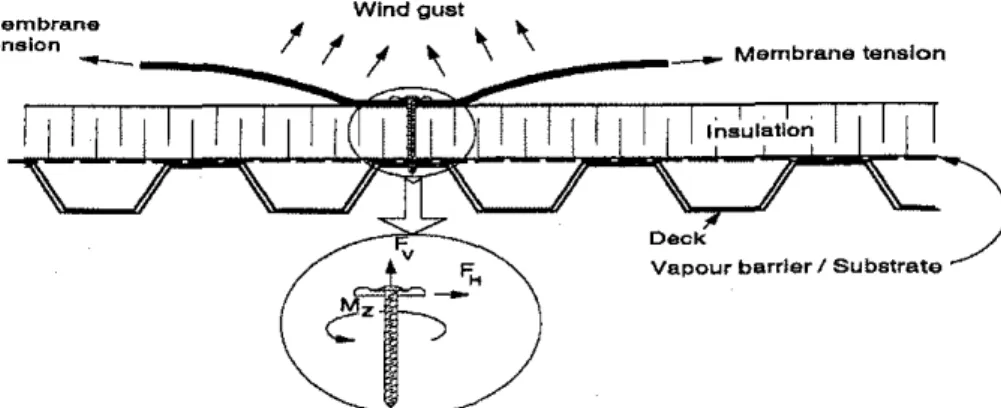
Membrane tensionFig.1. Spot-fastened single-ply roofing system and effect of dynamic loading on the fastener.
particular interest is their ability to handle the effects of wind flutter and fatigue caused by uplift forces of varying intensity and direction. Fig. 1 shows a typical spot-fastened mechanical single-ply system. The wind uplift forces deflect themem-brane causing memthemem-brane tension and loading on the fastener. The variation of wind-induced effects with time and space creates the phenomenon of dynamic wind loading on the fastener. Conditions similar to the spot fasteners apply to the strip fasteners as well. Spot-fastened systems subjected to asymmetrical loading are more vulnerable. When the fasteners are exposed to multi-directional wind forces rotation and rocking occurs. This causes fatigue deformation on the metal deck. This ulti-mately leads to a reduction in the pullout resistance of the fastener, a factor that must be accommodatedin the design of roof systems.
2, Existing evaluation procedures
Fatigue caused by wind flutter can significantly reduce failure loads and should be accounted for in the evaluation of roof systems. In Australia, Byrne [IJ, Morgan and Beck [2J and Mahendran [3J used an experimental setup to apply dynamic loading on sheet-metal roofing. Warshaw and Hoher [4J conducted dynamic testing on 10 x 10 ft panels of mechanically attached roof membranes. The simulation consisted of applying pulsating pressures to the panels and increasing the value by specified increments. Results showed that failure occurred at 50% of the static pullout specified by manufacturers. Studies conducted by Ellifritt and Burnette [5J investigated the effects of dynamic wind loading on the pull-over strength of fasteners. Dynamic loading was induced by applying cyclic loading on the adjacent purlin. Before failure of the connection occurred, the number of cycles were recorded and used to analyze different fastener configurations.
In Europe, the European Technical Construction Agreement (VEAtc) standard wind-uplift test method was prepared based on a procedure developed by Gerhardt
A. Baskaran, O. DuttlJ. Wind Eng. Ind. Aerodyn. 72 (1997) 389-400 391 and Kramer [6,7]. Itis intended for use throughout Europe and provides allowable loads per fastener for mechanically attached systems. This procedure attempts to simulate dynamic wind behavior. The wind load test cycle is based on accumulated probability distribution of wind velocity pressure derived from meteorological data. Problems associated with fasteners applied too close to the edge are controlled by use of larger test specimens。セ correction factors [8]. However, drawbacks associated with sheet distortion, perimeter and seal attachment that structurally reinforce test units may still be a problem according to Hasan and Ammerman [9]. Similarly, the British Research Establishment Real Time Wind Uniform Load Follower (BRER-WULF) may simulate loading pattern derived from wind records [10].
In North America, test procedures of Factory Mutual [lIJ and Underwriters Laboratories [12J are considered ad hoc standards for evaluating mechanically attached roof systems. Yet, following Hurricane Hugo, it was noted that roofs rated to sustain 150 MPH winds by FM (1-90) failed at winds of 40-60 MPH [13J Similarly, standing seam-metal roofs rated according to UL 580 failed at wind loads and wind speeds 20-60% of the expected capacity [14]. FM statistics showed that during the period of 1960-1990, 21 windstorms occurred and damages incurred on FM rated mechanically attached roofs totaled US $ 14 million [9].
A major flaw associated with FM 4470 and UL 580 is their lack of provisions for dynamic testing. Both tests are static and do not simulate the effect of dynamic wind fluctuations. Experts agree that static test methods need improvement because they are unable to simulate, realistically, field conditions [4,15-17]. Moreover, North-American test methods do not account for the effects of positive pressure from the building's interior [13]. A study by Zarghamee [18J, however, numerically modeled the effect of pressures below membranes and investigated failure mechanisms of mechan-ically-attached roof systems that account for air infiltration underneath the membrane. Baskaran and Dutt [17J of the Institute for Research in Construction, National Research Council of Canada (IRCjNRC) initiated a project, "Dynamic Evaluation of Roof Attachment Systems," that aims to evaluate mechanically attached roof systems under dynamic loading. The IRC/NRC project consists of four tasks: material inves-tigation, computer modeling, wind tunnel testing and development of design manuals. This paper reports the progress made on task one, material investigation. Experi-ments were conducted at IRC/NRC which investigated the static and dynamic pull-out strength of the roof fasteners installed in metal and wooden decks. Singularly, the pull-out load data identify the allowable fastener design load. In addition, the data are needed for future investigations to select the instrumentation range for wind-tunnel measurements and to formulate assumptions for the FEM model development.
3. Experimental procedure
3.1. Materials used
Specimens simulating a mechanically attached roof system were prepared by installing fasteners in steel and wooden roof decks. The material properties are described below.
392 A. Baskaran, O. DuU!J. Wind Eng. Ind. Aerodyn. 72 (1997) 389-400
3.1.1. Steel decks
Two types of 22-Gauge galvanized steel, one with and another without zinc coating were tested. The samples tested were cut from 0.76 mm thick corrugated sheets 610 mm long by 915 mm wide. The corrugations on both types of steel were similar. The sizes of the samples were 152 mm wide by 305 mm long.Itwas necessary to use these dimensions, since samples tested with shorter lengths (89 x 152 mm and 152 x 152 mm) provided inaccurate results owing to excessive sheet deformation. On the other hand, samples tested with 305 x 305 mm does not affect the pull-out strength of the fasteners. Note that the existing IRC/NRC facility can test samples with dimensions up to 457 x 610 mm. Steel deck specimens were prepared by installing fasteners through the lower horizontal section of profile (female rib) and the upper horizontal section of profile (male rib). In each case, the fasteners were centered with respect to length and installed with a minimum penetration of 19 mm.
3.1.2. Wooden decks
Two types of 12 mm thick wood-based decks were tested. One is the conventional plywood and the other is composed of wood fibers known as "Oriented Strand Board (OSB)". Test samples of 152 x 152 mm in size were prepared from 1219 x 2438 mm sheets. With wooden decks, fasteners were installed perpendicular to the grain at penetration depths of 38 and 89 mm. Penetration depth is the distance from the topside of the wood to the end of the fasteners.
3.1.3. Fasteners
The installed fasteners were 152 mm long with a thread length of 102 mm, having inner diameter of 5 mm and outer diameter of 6 mm. The fasteners were installed using a drill press. Special precautions were taken during the installation process to ensure that no bending of the sheet occurred and that the pressure applied during each application remained fairly constant. Similar fasteners were used for both wooden and steel decks and this will help in establishing a comparison between them.
3.2. Experimental setup for static and dynamic testing
Wind-induced loads on the membrane can reach the structural supporting system through two load paths: pneumatic load path and structural load path [19]. In the
pneumatic load path,the load is shared among the layers (membrane, insulation, and
deck) by differences in pressure across them. In thestructural load path,the load passes through the fasteners. If fluctuations of external wind pressures are slower than the membrane response time, the loads are transmitted through membrane tension to the fasteners, i.e.,structural load path.For fluctuations faster than the membrane response time, the load will be transmitted through pneumatic actions. Experimental investiga-tions by the present study were aimed to simulate thestructural load pathmechanism. In this experiment, IRC designed a loading cell attachment and a base to accommod-ate the samples for static and dynamic testing. This attachment system was connected to a computer-controlled Instron Model 4502 testing machine. The loading frame can
A. Baskaran, 0. DuttjJ. Wind Eng. Ind. Aerodyn.72 (1997)389-400 393
Fig. 2. Experimental setup used for the evaluations of fastener pull-out loads.
be adapted to test different specimen types by altering loading cells and grips. The dynamic setup is shown in Fig. 2.
The base was designed so that the sample was held down along its edges. The dynamic setup consisted of a gear and pulley device that produced a cyclic horizontal force on the fastener while the Instron simultaneously applied a vertical pulling force. The horizontal loading device was such that the neck of the fastener was gripped and an elliptical motion was induced on the fastener.Itis important to note that the device did not produce any twisting on the fastener. The device simulated the effect that a fluctuating membrane causes when subjected to dynamic wind loading. Experiments
394 A. Baskaran,O.Dutt/J Wind Eng. Ind. Aerodyn. 72 (1997)389-400
were conducted under static and dynamic loading conditions. For static testing, a constant upward force was applied by pulling the fasteners at the rate of 5 mm/min. Results under dynamic testing were obtained by using a static pulling rate of 5 mm/min together with a horizontal cyclic load having a maximum amplitude of 180N.
4. Results and discussion
The results are grouped according to the type of deck used, whether steel or wood.
4.1. Evaluation offastener pull-out load with steel decks
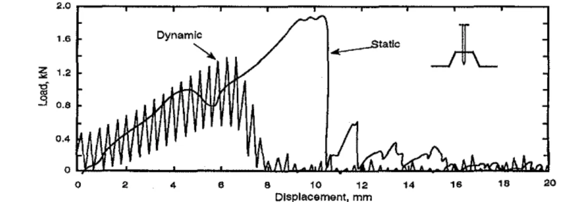
In Fig. 3 a typical load versus displacement recorded during the static and dynamic testing is being compared. The graph refers to results obtained from testing the fastener installed through the male rib. During the static testing, the fastener was gradually pulling out of the deck causing sheet deformation along the fastener's perimeter. Eventually, the fastener pulled out of the deck. In the case mentioned, the initial peak occurred at 1000 N followed by the maximum peak of 2000 N. The second peak represented the absolute failure of the connection since an entire thread was pulled out of the steel deck. Each subsequent peak refers to other threads being pulled out. The loads for pull-out decreased significantly following the initial failure. Sheet deformation around the fastener was about 4 mm vertically. The fastener threads were damaged by slight bending and loss of coating. The connection failure involved both the fastener and the steel deck.
Mean pull-out resistance was computed for each of the configurations from the results obtained by testing a minimum of 20 samples. In total, about 300 experiments were performed. Fig. 4 summarizes these test results. Static pull-out load was about 1800--2000 N, irrespective of the steel deck type and fastener position. The results for
2.0 1 .• ....---static
A
z セ-g
S 0.4 2•
•
•
10 12,.
,.
18 20 Displacement, mm2.0 , .5 ;;;; 1<f
...
, .0.,.
...
セ 0.5 0A. Baskaran, O. DuttfJ. Wind Eng. Ind. Aerodyn. 72 (1997) 389-400
With Zinc Coat
2.0
'.5 '-0
0.5
o
Fig. 4. Static and dynamic fastener pull-out loads with steel decks.
395
both materials indicate that a fastener installed through the female rib yields a weaker connection under dynamic testing. The fastener pull-out resistance was approximately 1000 N for fasteners installed through the female rib and 1300 N for fasteners installed through the male rib. Thus, the results of the experiment clearly indicated that dynamic loading significantly reduces the strength of mechanically fastened systems. This has been found to be true for the steel deck with and without zinc coating. The introduction of the cyclic horizontal load-induced fatigue in the metal sheet causes a 30-50% reduction in the pull-out resistance. The average reduction of fastener pull-out resistance was about 35 and 46% when the fasteners were positioned through the male rib and female rib, respectively.
4.2. Evaluation offastener pull-out loads with wooden decks
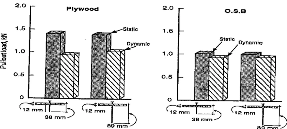
Results obtained for wood-based decks are presented in this section. In Fig. 5 static and dynamic pull-out loads are compared. Results are presented for two fastener penetration depths. Overall, static and dynamic pull-out loads were greater for plywood than OSB. This is found to be true irrespective of the fastener penetration depth. The difference between the two materials can be attributed to the strength contributed by the grain of the plywood. Plywood grains, having natural bonding, allowed the load to be more distributed thereby increasing the pull-out loads. OSB, on the other hand, a machine-made product from wood flakes, has low-bonding between the grains. This causes a reduction in both static and dynamic pull-out loads.
Further scrutiny of the fastener pull-out load results for two decks, wood and steel, reveal the following:
• Pull-out load does not vary between the testing samples in the case of steel decks. This is not true with wood decks. Therefore, more wood samples were tested to keep the standard deviation constant at 10%.
• Even though steel is much thinner than wood (0.76 mm in comparison to 12 mm), fastener pull-out loads are higher with steel decks. Two factors. contribute to the higher pull-out load with steel deck: first, Young's modules value of steel is high,
A. Baskaran, 0. DuttlJ. Wind Eng. Ind, Aerodyn. 72 (1997) 389-400 396 2.0 1.5 :;;;
1
1.0 セセ a-0.5 PlywoodイL[\セセ
89mm)
2.0 1.5 O.S.BFig. 5. Static and dynamic fastener pull-out loads with wooden decks.
E, = 200000 MPa, andEw(wood modules parallel to the grain)= 10000 Mpa; and
second, the steel deck takes a certaiu percentage of the pull-out load by deflecting before the fastener fails.
• Reduction in pull-out load due to dynamic testing is less for wooden decks (10-30%) in comparison to steel decks (30-50%).
4.3. Fastener service life predictions- preliminary results
Discussion of Sections 3.1 and 3.2 concentrated on static and dynamic pull-out loads. They are critical in determining the fastener design load with the respective deck compositiou. An equally important feature in fastener design is the prediction of its service life. For the steel deck, this phenomenon is influenced due to various factors such as fatigue loading, deck corrosion, thermal bridging and so on. For wooden deck, the factors influencing this phenomenon include moisture content, material non-homogeneity and so on. Efforts are in progress at'IRC/NRC to develop proper experimental procedures to account for some of these effects and to gather experi-mental data to predict fasteners' service life. Development of such design data is vital in re-roofing situations to determine the streugth of the existing fastening system. Along this view, two types of preliminary experimental results are reported below, one on fatigue loading on steel decks and other on water immersion effects on wooden decks.
4.3.1. Fatigue testing on steel decks
Fastener fatigue failures have been investigated by applying cyclic loading. In cyclic testing various percentages of the static pull-out load were specified as amplitude. For each amplitude, testing continued until the fastener pull-out occurred and the corre-sponding number of cycles taken for fastener failure was recorded. By recording the
A. Baskaran, O. Dutt!J. Wind Eng. Ind. Aerodyn. 72 (1997) 389-400
l,
OOrrrrrrrnr,,"1Tm7r"T'TrTTITIr-rr----,
セI
y ..·8.27 In 00+788
80··1
,'-0."
! J i8.
60 ...セNN ....セ...+.. o Ii
I
セ
401I-+t++ItifH-t++ItifH-t+mlkt-t++ItifH-'+-tiitHf
'6f
"
2 0 , , ' .. ,...,. I \ i i i i i i! i] i i セ セlNNLNNNキMLMBLLBMN」NNNキ]LlNoMwN]ャBGoMo,-,-,.w.,"'o-oo-'-"',",,""oooo
Number 01 cycle,Fig. 6. Required number of cycles for fastener pullout failure under cyclic loading.
397
number of cycles for fastener failure at a given percentage of the pull-out load and performing the tests at different percentages of static pull-out load, it is possible to characterize the fatigue failure of the fastener. Further, these cyclic test results can be suitably combined with the local climatic data (design wind pressures and return period) to predict the service life of roof attachment systems.
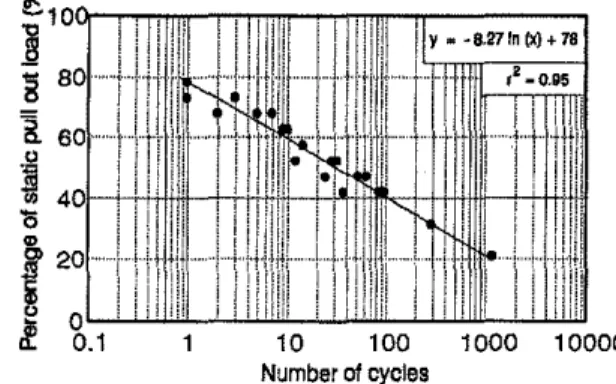
Examination of the developed cracks on the steel deck during the cyclic testing (not shown here) indicated that they started from the edge of the fastener holes and propagated in all directions. This indicates fatigue failure of the sheet. Fastener failure occurs owing to sheet fractures and leads to pullout failure. These fracture failures can lead to water leakage on roofing which could involve costly repairs or replacement of components before any structural damage is observed. Fig. 6 presents the results from cyclic testing. The x-axis, shown by log scale, displays the number of cycles.
Percentages of the static pull-out loads are shown in the vertical axis. In total, ten sets of tests were performed by varying the amplitude of the cyclic load to 21, 31,42, 47,52,57,63,68, 73 and 80% of the pull-out load. Tests loading above 80% were not performed due to the repeated loading of this magnitude will not occur in the field. Testing at rates lower than 20% of the pullout load were not performed because of the duration of the testing, e.g., cyclic experiments with 21 % of static pull-out load take about 17 h to complete. As mentioned before, these cyclic test results can be suitably combined with the local wind climatic data so that the service life for roof attachment system can be predicted. Future experimental work and data analysis are directed toward such kind of service life projections.
4.3.2. Water immersion effects on wooden decks
An extensive literature survey concluded that no ASTM testing method is currently available for the water immersion effects on wooden decks. Hence, samples were immersed in water for 3 and 7 days under controlled laboratory conditions of 24°C and 65% RH. Testing was conducted immediately following water immersion; no drying period was allowed. This method is not meant as an accurate representation for varying the water content with time on wooden decks. Visual observations of
398 A. Baskaran, 0.DuttjJ. Wind Eng. Ind. Aerodyn. 72 (1997) 389-400
イL[セ[AMRI
Stalk: 2.0 1.5 セi
1.0セ
"
a. 0.5 o Plywood 3 days 7days 2.0 1.5 1.0 0.5o
oss
3days 7daysFig. 7. Effect of water immersion on static and dynamic fastener pullout loads with wooden decks.
water-immersed plywood samples indicated very little dimensional change. Even after 7 days of continuous water immersion, plywood samples had swelled in thickness by only about I mm. Substantial dimensional change ofthe OSB samples was noted after water immersion. Following 3 days of water immersion, the average OSB sample thickness had increased by 4 mm; after 7 days of water immersion, no further increase in thickness was noted. Comparisons of test results are displayed in Fig. 7. Water immersion resulted in significant pullout reductions for both OSB and plywood samples. Decreases in pullout load were noted under both static and dynamic test conditions. After 7 days of water immersion, pull-out load reductions ranging from 20 to 35% were observed. The results of water immersion testing indicate that water damage to wood-based deck materials will result in a significant decline in fastener pull-out loads.
The parameters representing the amount of rain that actually strikes on the building envelope and its probability of occurrence are critical to develop a systematic experimental procedure for water content of the wooden deck and its effects on the fastener pull-out loads. Research efforts have started to develop a relationship be-tween the amount of wind-driven rain and driving-rain index [20J and Choi [21]. Preliminary data indicate that water immersion of wood significantly reduces the fastener pullout loads. Future research will focus on developing a suitable experi-mental procedure.
5. Concludingremarks
The IRC/NRC experiment has indicated that the fastener failure load and mode under dynamic testing differ significantly from those conventional static testings. With steel decks, the pull-out resistance of the fastener decreased by 30-50% with the introduction of a cyclic horizontal force simulating dynamic conditions, whereas
A. Baskaran, O. Dutt/J. Wind Eng. Ind. Aerodyn. 72 (1997) 389-400 399 results with wooden decks indicated a reduction of10-30%. Therefore, for the design of mechanically attached roofing systems, one should evaluate the allowable design load of the fastener through dynamic testing, Two types of preliminary experiments were performed to gather data for predicting fastener service life. Even though these trials identified the potential for such evaluation, further systematic investigation is needed to support the preliminary findings.
Acknowledgements
Part of this research project is jointly sponsored by IRC/NRC and the Department of National Defence (Mr.V. Walsworth), Authors indebted to the co-op students, Ms. L. Dodaro and Mr.C.Norris, who conducted the experiments for the data presented in the paper under the assistance of Mr. W. Lee, Technical Officer, at IRC/NRC. Materials used in the experiment were provided by Mr, M. Sommerstein (VicWest Steel), Mr. J. Bond (Canam Steel) and Mr. P. Fagan (Carlisle Syn Tee Systems Canada).
Amendment
Dr. Om Dutt, the paper's co-author, passed away in November1996and we would like to dedicate the paper for his contribution in establishing this project.
The above manuscript was prepared based on experimental investigation carried out in 1994. Significant progress made on this project and the new findings will be presented as"A New Facility for Dynamic Wind Performance Evaluation of Roofing
Systems- A. Baskaran and W, Lei"at the 4th International Symposium on Roofing
Technology, Washington, 17-19 September,1997.
References
[1J S.M. Byrne, Dynamic-load testing of sheet metal roofing, Metal Structures Conf., Adelaide, Australia, 25-26 November, 1976, pp. 46-50.
[2] l.W.Morgan, V.R. Beck, Failure of sheet-metal roofing under repeated wind loading, Trans. lost. Eng. Aust., Civil Eng. CE-19 (1977) 1-5.
[3] M. Maheodran, Fatigue behavior of corrugated roofing under cyclic wind loading, Trans. lnst. Eng. Aust., Civil Eng. CE-32 (4) (1990) 219-226.
[4J S.W. Warshaw,K.Hoher, Mechanical fastening of single-ply roof membranes into steel decks - An engineering evaluation, A Decade of Change and Future Trends in Roofing -1985, 2nd lnt. Symp. on Roofing Technology, 1985, pp. 183-193.
[5] D.S. Ellifritt, R. Burnette, Pull-over strength of screws in simulated building tests, 10th lnt. Specialty Conf. on Cold-Formed Stee! Structures, St. Louis, Missouri, USA, 1990, pp. 589-604.
[6J H.J. Gerhardt, C Kramer, Wind induced loading cycle and fatigue testing of lightweight roofing fixations, 1. Wind Eng. Ind. Aerodyn. 23 (1986) 237-247.
[7] H.J. Gerhardt, C. Kramer, Wind loading and fatigue behavior of fixings and bondings of roof coverings,1. Wind Eng. Ind. Aerodyn. 29 (1988) 109-118.
400 A. Baskaran, 0.DuttjJ. Wind Eng. Ind. Aerodyn. 72 (1997)389-400
[8J H,J, Gerhardt, RW. Gerbatsch, Wind resistance of mechanically attached, single·ply systems, fastener load, safety considerations and optimal fastener patterns, A Decade of Change and Future Trends in Roofing, Int. Symp. on Roofing Technology, National Roofing Contractors Association, USA, 1991, pp. 276-282.
[9J R Hasan, T. Ammerman, Framing new questions in FM single·ply testing,RoofingSiding Insulation, May 1992, pp. 32-33.
[10J N.J. Cook, A.P. Keevil, R.K. Stobart, BRERWULF - Tbe big bad wolf,1.Wind Eng. Ind. Aerodyn. 29 (1988) 99-107.
[11] Factory Mutual Research, Approval standard: class I roof covers (4470), 1151 Boston-Providence Turnpike, P.O. Box 9102, Norwood, Massachusetts 02023, USA, April 1988.
[12J Underwriters Laboratories Inc., Standard for Uplift Pressure of Roof Assemblies (UL 580), 3rd ed., 12 Laboratory Drive, RTP, NC 27709, USA, November 1991.
[13] S. Bieber, Hurricanes test roofs, Roofing'Siding Insulation, January 1990, pp. 60-.-61.
[14] R.C Decker, Technology transfer: roof failures pose industry alert, The Military Engineer Septem-ber/October 1989, p. 53.
[15] T. O'Dea, Oak ridge workshop keys on Hugo damage, Roofing Siding Insulation, January 1990, p.45.
[16] D. Fricklas, Knowing mechanically attached roofs, Roofing Siding Insulation, April 1990, p. 8. [17] A.Baskaran, O. Dutt, Putting roof fasteners to the test in high winds, Roofing Siding Insulation (1994)
60-62.
[18J M.S. Zarghamee, Wind effects on single-ply roofing systems, J. Struct. Eng. 116 (1990) 177-187. [19J N.J. Cook, Dynamic response of single-ply membrane roofing systems,1.Wind Eng. Ind. Aerodyn.
4H4 (1992) 1525-1536.
[20] E.C.C. Choi, Simulation of wind-driven rain around a building,1.Wind Eng. Ind. Aerodyn. 46-47 (1993) 721-729.
[21] F.A.M. Henriques, Quantification of wind driven rain. An experimental approach, Proc. 9th CIB Building Congr., Montreal, Canada, 1992, pp. 194-195.