Publisher’s version / Version de l'éditeur:
Journal of Cold Regions Engineering, 22, 4, pp. 103-123, 2008-12-01
READ THESE TERMS AND CONDITIONS CAREFULLY BEFORE USING THIS WEBSITE.
https://nrc-publications.canada.ca/eng/copyright
Vous avez des questions? Nous pouvons vous aider. Pour communiquer directement avec un auteur, consultez la
première page de la revue dans laquelle son article a été publié afin de trouver ses coordonnées. Si vous n’arrivez pas à les repérer, communiquez avec nous à [email protected].
Questions? Contact the NRC Publications Archive team at
[email protected]. If you wish to email the authors directly, please see the first page of the publication for their contact information.
NRC Publications Archive
Archives des publications du CNRC
This publication could be one of several versions: author’s original, accepted manuscript or the publisher’s version. / La version de cette publication peut être l’une des suivantes : la version prépublication de l’auteur, la version acceptée du manuscrit ou la version de l’éditeur.
For the publisher’s version, please access the DOI link below./ Pour consulter la version de l’éditeur, utilisez le lien DOI ci-dessous.
https://doi.org/10.1061/(ASCE)0887-381X(2008)22:4(103)
Access and use of this website and the material on it are subject to the Terms and Conditions set forth at
High performance vacuum insulation panel: development of alternative core materials
Mukhopadhyaya, P.; Kumaran, M. K.; Normandin, N.; van Reenen, D.; Lackey, J. C.
https://publications-cnrc.canada.ca/fra/droits
L’accès à ce site Web et l’utilisation de son contenu sont assujettis aux conditions présentées dans le site LISEZ CES CONDITIONS ATTENTIVEMENT AVANT D’UTILISER CE SITE WEB.
NRC Publications Record / Notice d'Archives des publications de CNRC: https://nrc-publications.canada.ca/eng/view/object/?id=bfd27cdc-f55a-468d-aaf5-3d4c046d4856 https://publications-cnrc.canada.ca/fra/voir/objet/?id=bfd27cdc-f55a-468d-aaf5-3d4c046d4856
http://irc.nrc-cnrc.gc.ca H i g h p e r f o r m a n c e v a c u u m i n s u l a t i o n p a n e l : d e v e l o p m e n t o f a l t e r n a t i v e c o r e m a t e r i a l s
N R C C - 4 9 4 9 3
M u k h o p a d h y a y a , P . ; K u m a r a n , M . K . ; N o r m a n d i n , N . ; v a n R e e n e n , D . ; L a c k e y , J . C .2 0 0 8 - 1 1 - 1 9
A version of this document is published in / Une version de ce document se trouve dans:
Journal of Cold Regions Engineering, v. 22, no. 4, 2008, pp. 103-123
The material in this document is covered by the provisions of the Copyright Act, by Canadian laws, policies, regulations and international agreements. Such provisions serve to identify the information source and, in specific instances, to prohibit reproduction of materials without written permission. For more information visit http://laws.justice.gc.ca/en/showtdm/cs/C-42
Les renseignements dans ce document sont protégés par la Loi sur le droit d'auteur, par les lois, les politiques et les règlements du Canada et des accords internationaux. Ces dispositions permettent d'identifier la source de l'information et, dans certains cas, d'interdire la copie de documents sans permission écrite. Pour obtenir de plus amples renseignements : http://lois.justice.gc.ca/fr/showtdm/cs/C-42
H
IGH
P
ERFORMANCE
V
ACUUM
I
NSULATION
P
ANEL
:D
EVELOPMENT
OF
A
LTERNATIVE
C
ORE
M
ATERIALS
By Phalguni Mukhopadhyaya
1, Kumar Kumaran
2, Nicole Normandin
3, David
van Reenen
3and John Lackey
3ABSTRACT
Energy efficiency of the built environment greatly depends on the performance of the insulating materials used in the building envelope construction. Vacuum insulation panels (VIPs) offer excellent thermal resistance properties that can enhance the energy efficiency of the insulating systems and provide savings in energy consumption. However, VIP systems are virtually unknown and rarely used for building construction in North America. There is a need to investigate the use of VIPs in various components of building envelopes and their long-term performance. The National Research Council (NRC), Canada, Institute for Research in Construction (IRC) is investigating a number of fundamental aspects related to the performance and construction of VIP, which this paper discusses. More specifically, it reviews the underlying basics behind the functioning of VIPs and presents results from the investigation into the development of alternative core materials for VIP construction.
KEYWORDS: Thermal Insulation; Vacuum Insulation Panel; Core Materials; Building Envelopes; Energy Efficiency.
1
Associate Research Officer, Institute for Research in Construction, NRC Canada, Ottawa, Ontario, Canada.
2
INTRODUCTION
Existence of life on our planet is very much dependent on insulation. The layer of air that encompasses our planet is essentially an effective insulation blanket (Pelanne, 1978) keeping our
planet inhabitable for us. In a more day-to-day life our interaction with insulating materials and systems is a recurring theme (thermos flask, clothing, fur, window glass, building envelope etc.). The search for a better and/or cost efficient insulation system remains an ongoing process involving the development of innovative technologies (Stovall, 1999; Kollie et al. 1991).
The energy crisis of the 1970’s called for a review on how building envelopes are insulated and the system is built upon to reduce heat losses and improve energy efficiency of built environment. Canada, a country with very cold climate, was in the forefront of this technology and a renowned leader of research and development activities at that time. However, further technological developments in the area of insulation technology and recent global concerns about the climate change phenomenon show that there is room and need for improvement in the insulation technology for building envelopes. Hence, National Research Council (NRC) Canada, Institute for Research in Construction (IRC) has established a research program, supported by the Climate Change Technology Initiative (CCTI) of Canada, that broadly focuses on applicability of high performance vacuum insulation panel (VIP) in the building envelope construction. The following sections of this paper presents the basics principles of high performance vacuum insulation technology and presents some selected results from this ongoing research program that focuses on the development of alternative core materials for VIP.
BASIC PHYSICS OF HEAT TRANSFER
There are three basic heat transfer mechanisms that control the insulating capacity of conventional thermal insulation materials and these mechanisms (Figure 1) are: (1) Conduction,
(2) Convection, and (3) Radiation.
Conduction occurs when constituent particles of the insulating material are in physical contact and energy is transferred through this contact.
Convective heat transfer happens as a result of energy transfer by moving constituent particles (i.e. gas or fluid) of the insulating material.
Radiation takes place due to the emission of electromagnetic waves that transfer energy from the hot emitting object to a cold receiving surface and unlike conduction or convection this mode of heat transfer can take place when there is no contact medium (i.e. vacuum) between two objects.
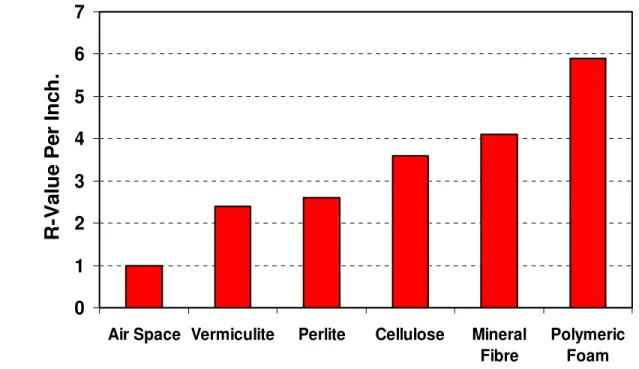
HIGH PERFORMANCE THERMAL INSULATION
The need to control the heat flow is very critical for the proper functioning of the biological, chemical and mechanical processes that are considered the basic foundation blocks of modern civilization. The most basic form of thermal insulation that had been used for the construction of the built environment is the ‘air space’ between two layers of construction. With a better understanding of heat transfer mechanisms and the advent of advanced manufacturing technology, the development of high performance insulation has been relatively slow but steady in terms of the increased R-value of the thermal insulation. Each of the thermal insulations mentioned in Figure 2 has been recognized as ‘high performance thermal insulation’ until the
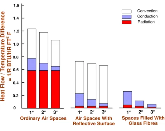
However, even now, enormous potential still exists to develop high performance thermal insulating materials and systems for the built environment construction and the fundamentals of this development lie within the basics of heat transfer mechanisms through the air space. As shown in Figure 3 (Shirtliffe 1972), heat flow through typical air space is primarily due to
convection and radiation. However, the introduction of reflective surface in the airspace can reduce the radiation component of the heat flow to a minimum level. Furthermore the addition of some fibrous materials that restricts the airflow inside the air space can eliminate the convective heat flow phenomenon almost entirely.
Hence, in any conventional insulation material, the three major components of heat flow are: (1) air conduction, (2) radiation and (3) solid conduction (Figure 4). The solid conduction and
radiation components are functionally related to the bulk density of the insulation materials. However, the air conduction is an independent component and offers a significant opportunity to develop high-performance insulation materials by effectively reducing this component.
The reduction of thermal conduction through air (i.e. air conduction) can be done in two different ways: (1) using a blowing agent gas, in place of air, with a thermal conductivity less than that of air, or (2) reducing the air pressure below the atmospheric level inside the insulation material. The first approach is the key for the development of closed-cell foam insulation where the gaseous blowing agents having thermal conductivity lower than air replace the air inside the closed cells. In effect, this approach reduces the air conduction component of thermal conductivity significantly depending on the type of blowing agent used in the closed-cell foam insulation, as shown in Table 1 (Wu and Eury, 2002). The thermal conductivity of most of the
commonly used blowing agents is lower than half of the thermal conductivity of air. The researchers at the National Research Council (NRC) Canada, Institute for Research in
Construction (IRC) have been working on the performance of closed-cell foam insulation for more than 15 years now (Kumaran et al. 1989; Bomberg and Kumaran, 1991; Mukhopadhyaya
et al. 2004). This research effort has so far culminated to the development of a standard test
method for determination of long-term thermal resistance (LTTR) of closed-cell thermal insulating foams (CAN/ULC-S770).
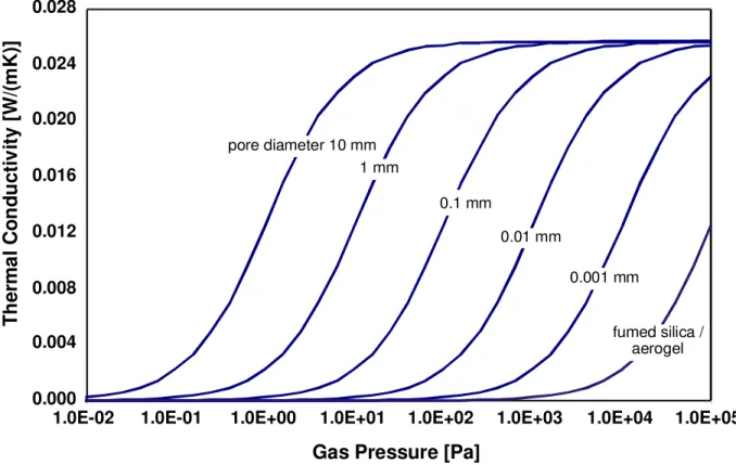
The second approach that reduces the air pressure inside the insulation material to increase the thermal resistance is a relatively new area of applied insulation research though the fundamental concept had been known for several decades (Verschoor et al. 1952). The increase of thermal resistance with the decrease of air pressure is also known to be a function of effective pore size of the insulation material (Kistler, 1935). The thermal conductivity of air decreases with the decrease of effective pore size as shown in Figure 5 (Simmler et al. 2005). Despite having all
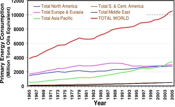
these fundamental physics known to the researchers the application of this concept for the development of ‘high-performance thermal insulation’ did not take place until now. This could be due to the absence of a suitable practical vacuum technology to create and maintain very low levels of air pressure inside the insulation material during their service life. However, recent global consciousnesses about the necessity to conserve energy and the spiraling demand for energy (Figure 6) have refocused attention on high-performance insulation research. The most
notable and comprehensive initiative has been the recently completed IEA/ECBCS Annex 39 project on vacuum insulation panels (VIP), HiPTI - high performance thermal insulation systems (Simmler et al. 2005; Binz et al. 2005). The NRC-IRC participated in this international collaborative research initiative as the Canadian representative. Other contributing countries were Switzerland, Germany, France, the Netherlands and Sweden (http://www.ecbcs.org/annexes/annex39.htm).
VACUUM INSULATION PANELS
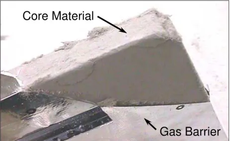
The construction of vacuum insulation panels is strictly based on the physics that the absence or reduction of gaseous pressure inside a porous material increases its thermal insulating potential. Accordingly a VIP is made with open porous core materials enclosed in an impermeable gas barrier (Figure 7a) and has three major components (Figure 7b).
1. A core material imparts mechanical strength and thermal insulating capacity by preventing the free flow of the gas/air molecules thereby reducing the ability of heat transfer through air conduction. Ideal core materials should have an open cell structure, very small pore diameter, resistance to compression due to atmospheric pressure and very high resistance to infrared radiation.
2. The gas barrier/facer foil provides the air and vapour-tight enclosure for the core material. The long-term performance of the VIPs is very much dependent on the performance of the gas barrier of facer foil.
3. Getter/desiccant is added inside the core material to adsorb residual or permeating atmospheric gases or water vapour in the VIP enclosure. The addition of getter/desiccant increases the performance and longevity of VIPs.
VIP – Advantages
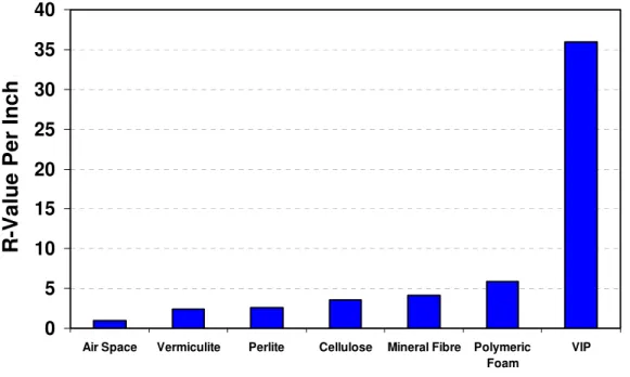
The thermal insulating capacity of VIPs is several times (up to 10 times) higher than conventional insulating materials (Figure 8). The panels are particularly useful in places where
space is at a premium or where energy demand is high, such as the Canadian North. The higher insulating values of VIPs can effectively reduce the thickness of building envelopes. In cases
where the size of framing members is governed by their ability to contain insulation materials rather than by structural strength, the size of insulation cavities can be reduced, with a saving in materials, a maximization of usable building space and a reduction in waste and recycling needs at the end of the building service life.
SEARCH FOR ALTERNATIVE CORE MATERIALS
Researchers from the NRC-IRC have been working on the various issues related to the long-term performance and material characterizations during the last five years. These investigations have been carried out either through national or international collaboration.
Laboratory studies on the vacuum insulation panels revealed its remarkable ability to maintain its thermal characteristics and internal pore pressure at a very low level after exposure to high relative humidity (90%) and temperature (32°C) conditions (Kumaran et al. 2004;
Mukhopadhyaya et al. 2005; Simmler et al. 2005). However, despite the superior thermal
performance of the VIP, the cost of the VIP still remains one of the major stumbling blocks that is holding back the wide application of VIP in the construction industry. The NRC-IRC is now working on the ways to bring down the cost of the VIP. To start with, research initiative is currently focussed on the development of alternative core materials for the construction of VIP.
Why Focus on Core Materials?
Long-term thermal performance of the vacuum insulation panel depends primarily on the gas barrier/ foil facer and the core material. While the gas barrier helps to maintain the air and vapour tight environment, the core material provides the insulating capacity. Recent studies at the NRC-IRC have indicated that commercially available vacuum technology and the foil
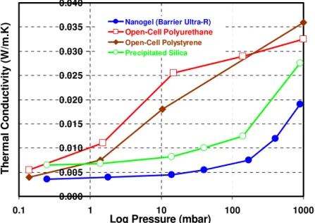
materials provide effective resistance against air and vapour permeation through the gas barrier (i.e. facer) and the facer seam (Mukhopadhyaya et al. 2005; Simmler et al. 2005). However, NRC-IRC studies have indicated that air and/or vapour will slowly and steadily penetrate into the core material, and this will raise the internal pore pressure and thermal conductivity of core material (i.e. reducing the thermal insulating capacity of the vacuum insulation panel). The extent of this thermal insulating capacity reduction depends at the initial stage on the capacity of the getter/ desiccant material to adsorb residual or permeating atmospheric gases or water vapour inside the VIP enclosure but ultimately on the relationship between pore pressure and the thermal conductivity change of the core material. The most commonly used core materials, as reported in the literature, are glass fibre, open-cell polyurethane foam, open-cell polystyrene foam, precipitated silica and nanogel (e.g. carbon/silica aerogel). The relationship between the thermal conductivity and the pore pressure for these materials is shown in Figures 9a and 9b
(Heinemann et al. 1999 and Glacierbay website). It is very obvious from these figures that there is a threshold limit of pore pressure beyond which the thermal conductivity of the core materials increases almost exponentially and for some core materials this threshold value is as low as around 10 Pa and for some others it is as high as 10000 Pa. This phenomenon concerning the ability of the open-porous core material to maintain lower thermal conductivity at higher pore pressure is directly related to the pore structure of the material (Tye 1969; Simmler et al. 2005). Core materials with smaller open pores have the greater ability to maintain lower thermal conductivity at higher pore pressure (Figures 9a and 9b). For this reason precipitated silica,
fumed silica and nanogel materials with micro or nano-porous structure maintain a very low vacuum-level thermal conductivity characteristic up to a pressure level of 10,000 Pa, unlike glass fibre, open-cell polyurethane foam and open-cell polystyrene foam. Incidentally, nano-porous
thermal insulating core materials are much more expensive than micro-porous materials. This is not because the basic materials required for the construction of nano-porous material are expensive but the manufacturing process to impart the nano-porous open-cell structure is very cost intensive. Quite naturally, the expensive core material is one of the main reasons behind the higher cost of vacuum insulation panels that offer a satisfactory long-term service life of the building envelope.
To overcome this cost barrier for the mass application of vacuum insulation panels in the building industry, NRC-IRC researchers are engaged in a research project (Mukhopadhyaya,
2006) that investigates the development of alternative core materials for the vacuum insulation
panel.
APPARATUS FOR INVESTIGATION ON CORE MATERIALS
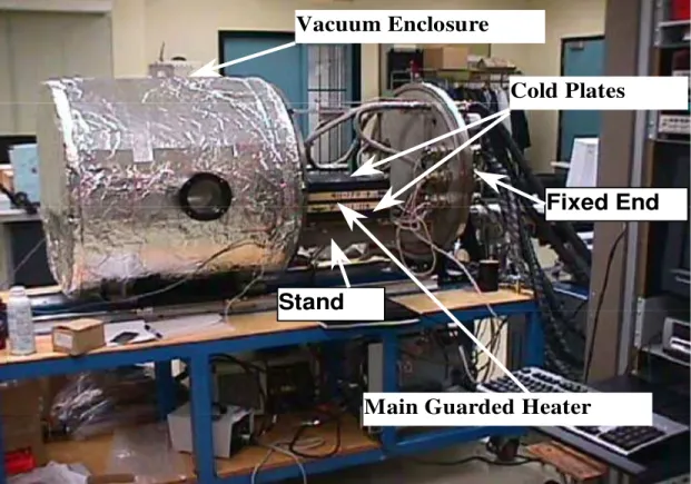
The NRC-IRC has recently developed a test apparatus, called a vacuum guarded hot plate or VGHP (Figure 10) that can characterize the thermal conductivity of open-porous insulating
materials at various pressure levels, from atmospheric to vacuum.
Construction of VGHP
In principle, vacuum guarded hot plate or VGHP is a traditional guarded hot plate (GHP) that operates in an environment where the pressure can be changed from atmospheric (≈ 100,000 Pa) to very low level (≈5Pa). The basics of VGHP construction can be found in the literature. The most recent one is from the National Physical Laboratory (NPL), Teddington, UK (Stacey,
2002).
(1) A pair of cold plates, (2) Main guarded hot plate,
(3) Auxiliary heater plate (used in single sided mode), and
(4) Vacuum chamber that encloses the guarded hot plate apparatus.
The guarded hot plate (300 mm x 300 mm) inside the vacuum chamber conforms to the ASTM standard C177 ‘Standard Test Method for Steady-State Heat Flux Measurements and Thermal Transmission Properties by Means of the Guarded Hot Plate Apparatus’, or the ISO standard 8302 ‘Thermal Insulation-Determination of Steady-State Thermal Resistance and Related Properties - Guarded Hot Plate Apparatus’. Repeated international round robin tests have confirmed that guarded hot plate apparatus at the NRC-IRC provides thermal conductivity measurements uncertainties within 1.5% (Zarr et al. 1997 ; Zarr et al. 2002; Zarr and Filliben,
2002).
DEVELOPMENT OF ALTERNATIVE CORE MATERIALS
More recently, NRC-IRC researchers have developed two new candidates as potential alternatives for core materials. The use of locally available traditional insulating materials and inexpensive manufacturing technique bring down the cost of the VIP significantly. These materials are essentially layered composites made with thin slices of fibrous insulation board and fine insulating powder material. Two fibrous insulation materials considered in this study are mineral oxide fibreboard (MOF) and high-density glass fibreboard (HDGF), and the powder material under consideration is pumice. At first the thermal properties of these materials were determined individually and then as a composite, as described in the following paragraphs.
Fibrous Insulation Boards
Two fibrous insulation boards under consideration are mineral oxide fibreboard or MOF (230 kg/m3) and high-density glass fibreboard or HDGF (104 kg/m3). Thermal properties of these types of open porous materials at atmospheric pressure and at other pressure levels close to vacuum are well known and had been reported in the literature (Heinemann et al. 1999; Simmler
et al. 2005). Thermal measurements done at the NRC-IRC using the VGHP apparatus (mean
temperature ≈ 26 ± 2°C) at various pressure levels on mineral oxide fibreboard and high-density glass fibreboard are shown in Figure 12. These results show comparable trend and values
reported for similar materials in the literatures (Heinemann et al. 1999; Simmler et al. 2005). These curves (thermal conductivity vs. logarithmic pressure) are usually expected to be smooth, however, there could be occasional minor irregularities as shown in Figure 12 for high density
glass fibre insulation board between the pressure range 1,000 and 10,000 Pa. These could result from the rearrangement of the fibre packing structure and change in solid contact surface area due to the change of internal pressure inside the fibrous structure. Removal of water vapour present in the porous structure during the evacuation process can also lead to small or abrupt changes in the thermal conductivity during the evacuation process. However, as could be seen in Figure 12 the thermal conductivities of mineral oxide fibreboard and high-density glass
fibreboard rise rapidly with the increase of pore pressure, unlike precipitated/fumed silica or the nanogel materials (see Figure 9a). In fact, fibrous insulation materials considered in this study
lost almost 80% of their thermal insulating capacity at pore pressure level 10,000 Pa compared with their capacity at lower pressure level (around 10 Pa, see Figure 12). Whereas
precipitated/fumed silica or the nanogel materials retain almost 80% of thermal insulating capacity at pore pressure 10,000 Pa. The weak potential of the fibrous insulating materials to
retain the thermal insulating capacity is related to the size of its pore structures as shown in scanning electron microscopic (HITACHI S4800) pictures (Figures 13 and 14). These pictures
(Figures 13 and 14), having same scale, clearly demonstrate that the diameter of the fibres and
the pore space between the fibres are much larger in the high-density glass fibre insulation board than the mineral oxide fibreboard.
Powder Insulation Materials
Finely graded powders have been used as core materials for evacuated panels for its premium thermal performance (McElroy et al. 1990; Stovall et al. 1997). These insulating powders offer very low thermal conductivity at vacuum or low pore pressure. However, loss of thermal insulating capacity of the powders with the increase of pore pressure depends on the particle size distribution and the filler materials used. The powder material under consideration in this study is pumice (amorphous aluminium silicate). Pumice powder is made from the pumice rock, a very light coloured, and frothy volcanic rock that is formed from lava that is full of gas. The particle size distribution curve of the finely graded pumice powder has been generated in the NRC-IRC’s laboratory using a particle analyzer (MALVERN Mastersizer 2000), with water as dispersing agent, as shown in Figure 15.
In order to determine the R-value of the pumice powder at various pressure levels, a purpose-built ‘evacuation box’ has been assembled in the laboratory. The powder filled evacuation box is placed between the hot and cold plates of the guarded hot plate. The box (Figures 16 and 17) is made with thin (5 mm) laminated plastic sheets. The inside dimension of the box is 275 mm × 275 mm × 25 mm. There are four rectangular (45 mm × 15 mm) openings on each edges of the box to carry out the gas evacuation process. These openings are covered with HEPA (High
Efficiency Particulate Air) filters that do not allow the powder particles to move out of the box during the evacuation process. The inside surfaces of the box is sprayed with black paint (emissivity ≈ 0.9). Also, several channels are engraved on the inner top and bottom cover plate surfaces for the placement of thermocouples (Figure 17).
The thermal properties of the pumice powder were measured twice in this study. In the first case, the virgin (i.e. as it was received from the manufacturer) powder was packed to a density of 668 kg/m3 inside the evacuation box and thermal properties were measured using the VGHP apparatus (mean temperature ≈ 24 ± 2°C). In the second case, the evacuated powder from the first case was taken out from the evacuation box and then put back (660 kg/m3) again inside the box for the repeat thermal measurement (mean temperature ≈ 24 ± 2°C). The results from these two measurements are shown in Figure 18. The initial and repeat thermal measurements are found to be different. These kinds of observations are not very unusual (Heinemann, 2005). Though the exact reason is difficult to pinpoint, however, in this case the difference in thermal measurement data could be because of the powder particle redistribution and reorientation of pore structures due to the change of pore pressure. Further investigation on this issue will be carried out with future experiments.
New Composite Core Materials
Two new alternative composite materials have been investigated in this study. These alternative composite core materials are made with fibrous and powder insulation materials. The first composite core material (340 kg/m3) has thin layers (≈ 3.5 mm each) of mineral oxide fiberboard and pumice powder sandwiched together as shown in Figure 19. In the second composite (320
fiberboard (HDGF). These composite materials were placed inside the evacuation box (Figure
16) and thermal properties were measured using the VGHP apparatus (mean temperature: MOF = 27°C; HDGF = 25°C). The relationship between the pore pressure and the thermal conductivity of these two newly introduced alternative core materials is shown in Figure 20.
This figure also draws comparison between the thermal properties of traditionally expensive core materials (precipitated silica and nanogel) and the newly developed alternative core materials. Although at atmospheric pressure level (≈100,000 Pa) the thermal conductivity values of the composite core materials are much higher than the precipitated silica and nanogel, the thermal conductivity values from the very low (≈ 25 Pa) to 10,000 Pa pressure level are very much comparable with that of precipitated silica or nanogel. The density of these two composite core materials is much lower than the powder material alone (≈ 668 kg/m3
) but it is higher than the fiberboards used in this study or most of the traditional insulating materials (maximum up to 110 kg/m3). However, there remains further scope to reduce the density of the newly developed composite core materials. In general, newly introduced composite core materials are potentially attractive materials for the development of alternative vacuum insulation panels. NRC-IRC researchers are working on these two new alternative core materials for further development and refinement and the detailed outcome will be published in due course.
CONCLUDING REMARKS
1. From theoretical and practical point of view and with the effective vacuum technology available at this moment vacuum insulation panels (VIPs) offer a great new opportunity for the global thermal insulation industry.
2. Use of VIPs in the building envelope industry can potentially cut down the operational energy consumption for the built environment and material use for the building envelope construction.
3. Current research activities at the NRC-IRC are contributing positively towards the development of alternative core materials necessary to produce relatively cheaper vacuum insulation panels for the construction industry.
4. Performance of vacuum insulation panels with the newly developed alternative core materials will be investigated at the NRC-IRC in coming days.
ACKNOWLEDGEMENT
The financial helps provided by the Climate Change Technology Initiatives (CCTI), Canada Mortgage and Housing Corporation (CMHC), Natural Resources Canada (NRCan), and Kingspan Insulated Panels for the NRC-IRC’s research on VIPs are highly appreciated.
REFERENCES
1. ASTM standard C177 (2005) ‘Standard Test Method for Steady-State Heat Flux Measurements and Thermal Transmission Properties by Means of the Guarded Hot Plate Apparatus’ ASTM International, 100 Barr Harbor Drive, PO Box C700, West Conshohocken, PA, 19428-2959, USA.
2. Binz, A., Moosmann, A., Steinke, G., Schonhardt, U., Fregnan, F., Simmler, H., Brunner, S., Ghazi, K., Bundi, R., Heinemann, U., Schwab H., Cauberg, H., Tenpierik, M., Johannesson, G., and Thorsell, T. (2005) “Vacuum Insulation in the Building Sector - Systems and Applications (Subtask B)” IEA/ECBCS Annex 39, pp. 1-134.
3. Bomberg, M.T. and Kumaran, M.K (1991) "Evaluation of long-term thermal performance of cellular plastics revisited," ASTM Special Technical Publication, 1116, Symposium on Insulation Materials: Testing and Applications (Gatlinburg, TN, USA, October 10, 1991), Philadelphia, PA: The American Society for Testing and Materials, pp. 123-141, (ISBN: 0803114206), (NRCC-35950) (IRC-P-3197 ASTM-STP-1116). 4. BP Statistical Review of World Energy June 2006 (http://www.bp.com/statisticalreview). 5. CAN/ULC-S770 (2003) ‘Standard Test Method for Determination of Long-term Thermal
Resistance of Closed-cell Thermal Insulating Foams,’ Underwriters' Laboratories of Canada, 7 Underwriters Road, Toronto, Ontario M1R 3B4, Canada.
6. Heinemann U., R. Caps and J. Fricke, (1999) ‘Characterization and Optimization of Filler Materials for Vacuum Super Insulations,’ Vuoto scienza e tecnologia, Vol. 28, N. 1-2 1999, p. 43-46, ISSN 0391-3155.
7. Heinemann, U., (2005) ‘Influence of Water on the Total Heat Transfer in ‘Evacuated’ Insulations,’ 7th International Vacuum Insulation Symposium, 23-34, 2005.
8. ISO 8302:1991, ‘Thermal Insulation -- Determination of Steady-State Thermal Resistance and Related Properties -- Guarded Hot Plate Apparatus’, International Organization for Standardization (ISO), 1, ch. de la Voie-Creuse, Case postale 56,CH-1211 Geneva 20, Switzerland.
9. Kistler, S. S. (1935) "The Relationship Between Heat Conductivity and Structure in Silica Aerogel", Journal of Physical Chemistry, Vol. 39, 1935, p. 79.
10. Kollie, T. G., McElroy, D. L., Fine, H. A., Childs, K. W., Graves, R. S., and Weaver, F. J., (1991) “A Review of Vacuum Insulation Research and Development in the Building
Materials Group of the Oak Ridge National Laboratory,” Oak Ridge National Laboratory, Oak Ridge, Tennessee 37831-6092, September 1991, pp. 91.
11. Kumaran, M. K., Mukhopadhyaya P., Lackey, J., Normandin, N., and van Reenen, D (2004) “Properties of Vacuum Insulation Panels: Results from Experimental Investigations at NRC Canada”, Joint NSC (Taiwan)/NRC (Canada) Workshop on Construction Technologies, Taipei, Taiwan, pp. 147-156.
12. Kumaran, M.K., Bomberg, M.T., Marchand, R.G., Ascough, M.R. and Creazzo, J.A (1989). "A Method for evaluating the effect of blowing agent condensation on sprayed polyurethane foams," Journal of Thermal Insulation, 13, (Oct), pp. 123-137, October, 1989 (Also published in "CFCs and the Polyurethane Industry: Vol 2 : (A Compilation of Technical Publications, 1988- 1989)"), (NRCC-35473) (IRC-P-3106).
13. McElroy, D. L., Weaver, F. J., Yarbrough, D. W, and Graves, R. S. (1990) “ Thermal resistance of fine powders at atmospheric pressure and under vacuum”, Insulation Materials, Testing, and Applications, ASTM STP 1030, D. L. McElroy and J. F. Kimpflen, Eds., American Society for Testing and Materials, Philadelphia, 1990, pp. 52-65.
14. Mukhopadhyaya, P. (2006) “High Performance Vacuum Insulation Panel – Research Update from Canada”, Global Insulation, October 2006, pp. 9-15.
15. Mukhopadhyaya, P., Bomberg, M.T., Kumaran, M.K., Drouin, M., Lackey, J.C., van Reenen, D., and Normandin, N. (2004) "Long-term thermal resistance of polyisocyanurate foam insulation with gas barrier," IX International Conference on Performance of Exterior Envelopes of Whole Buildings (Clearwater Beach, Florida,
December 05, 2004), pp. 1-10, December 01, 2004, (NRCC-46881), URL: http://irc.nrc-cnrc.gc.ca/pubs/fulltext/nrcc46881/.
16. Mukhopadhyaya, P., Kumaran, K., Lackey, J., Normandin, N. and van Reenen, D. (2005) “Long-term Thermal Resistance and Use of Vacuum Insulation Panel in Buildings”, 10th Canadian Conference on Building Science and Technology, 2005, Ottawa, Canada.
17. Pelanne, C. M. (1978) “Thermal insulation: what it is and how it works”, Journal of Thermal Insulation, Volume 1, April 1978, pp. 223-236.
18. Shirtliffe C.J. (1972) “Thermal Resistance of Building Insulation” CBD-149. Institute for Research in Construction, National Research Council, Ottawa, Canada.
19. Simmler, H., Brunner, S., Heinemann, U., Schwab, H., Kumaran, K., Mukhopadhyaya, P., Quénard, D., Sallée, H., Noller, K., Kücükpinar-Niarchos, E., Stramm, C., Tenpierik, M., Cauberg, H., Erb, M., (2005) “Study on VIP-components and panels for service life prediction of VIP in building applications (Subtask A)”, IEA/ECBCS Annex 39, pp. 1-157.
20. Stacey, C. (2002), “NPL Vacuum Guarded Hot-Plate for Measuring Thermal Conductivity and Total Hemispherical Emittance of Insulation Materials”, Insulation Materials: Testing and Applications, 4th Volume, ASTM STP 1426, A. O. Desjarlais and R. R. Zarr, Eds., ASTM International, West Conshohocken, PA, pp. 131-144.
21. Stovall, T. K., (1999) “An Introduction to VIP Technology,” Vacuum Insulation Panel Symposium, Baltimore, May-3-4, 1999.
22. Stovall, T., Wilkes, K., Nelson, G. and Weaver, F. (1997) “An evaluation of potential low-cost filler materials for evacuated insulation panels”, 24th International Thermal Conductivity Conference, October 26-29, Pittsburgh, Pennsylvania, USA, pp. 437-449.
23. Tye, R. P. (Editor) (1969), “Thermal Conductivity”, Vol. I, Academic Press, London and Newyork, SBN: 12-705401-4.
24. Verschoor, J. D., Greebler, P., and Manville, N. J. (1952). “Heat Transfer by Gas Conduction and Radiation in Fibrous Insulation”, Transactions of the American Society of Mechanical Engineers, V. 74, pp. 961-968.
25. Wu, J. and Eury, S. (2002) “HCFC and HFC Alternative Blowing Agents”, PU China, April 2002, © Arkema Inc., pp. 10.
26. Zarr, R. R., Kumaran, M. K., and Lagergren, E. S. (1997), ‘NIST/NRC-Canada Interlaboratory Comparison of Guarded Hot Plate Measurements: 1993-1997’, NISTIR, 6087, pp. 9, (NRCC-41867) (NISTIR 6087), URL: http://irc.nrc-cnrc.gc.ca/pubs/fulltext/nrcc41867.
27. Zarr, R. R., Filliben, J. J., Uezono, M., Venuti, G., Quin, S., Salmon, D., Tye, R., Kumaran, M. K., Tariku, F., Pauwels, J., Lamberty, A., and Ingelbrecht, C. (2002), ‘International Comparison of Guarded Hot Plate Apparatus Using National and Regional Reference Materials, NIST Technical Note 1444, May, pp. 1-88, May 01, 2002, (NRCC-45713) (NIST-TN-1444).
28. Zarr. R. R. and Filliben. J. J. (2002), ‘International Study of Guarded Hot Plate Laboratories Using Fibrous Glass and Expanded Polystyrene Reference Materials’, Insulation Materials: Testing and Applications, Volume 4. ASTM STP 1426. 2002, ASTM International, West Conshohocken, PA, Desjarlais, A. O., Zarr, R. R., Editor(s), pp. 3-16.
Table 1 – Thermal conductivity of blowing agents Blowing Agent Thermal Conductivity [kgas @ 25 (°C) mW/m.K] CFC-11 8.7 HCFC-141b 9.7 HCFC-142b 11.5 HCFC-22 11.0 Hydrocarbon c-C5 12.0 Hydrocarbon n-C5 15 HFC-134a 13.6 HFC-245fa 12.2 HFC-365mfc 10.6 Air 26
Figure 1 - Basic physics of heat transfer mechanisms Figure 2 - R value of commonly used insulating materials
Figure 3 - Heat transfer across air spaces – contribution by radiation, conduction and convection
Figure 4 - Heat transfer mechanisms in conventional (fibres and foam) insulation Figure 5 – Thermal conductivity of air as a function of pore diameter
Figure 6 – Global trend of energy consumption (Source: BP statistical review of world
energy June 2006)
Figure 7a – Vacuum insulation panel
Figure 7b – Schematic construction of vacuum insulation panel
Figure 8 - Thermal resistivity of VIP compared against several common insulating materials
Figure 9a – Change of thermal conductivity of core material with the pore pressure (Source: Heinemann et al. 1999)
Figure 9b – Change of thermal conductivity of core material with the pore pressure (Source http://www.glacierbay.com/vacpanelinfo.asp)
Figure 10 – Vacuum guarded hot plate (VGHP) apparatus
Figure 11 – Schematics of the plate assembly in single- and double-sided heat flow mode
Figure 12 – Thermal properties of fibrous insulating materials Figure 13 – Pore and fibre structure of mineral oxide fibre board Figure 14 – Pore and fibre structure of glass fibre insulation board Figure 15 – Particle size distribution (pumice powder)
Figure 16 – Evacuation box for the powder material Figure 17 – Inside of the evacuation box
Figure 18 – Thermal properties of pumice powder Figure 19 – Composite fibre-powder insulation
(c) Radiation – Heat Transfer Due to Emission of Electromagnetic Waves. (b) Convection – Heat Transfer in a Flowing Medium.
(a) Conduction – Heat Transfer Through Particle Contact.
Figure 1 - Basic physics of heat transfer mechanisms
.
Figure 2 - R value of commonly used insulating materials 0 1 2 3 4 5 6 7
Air Space Vermiculite Perlite Cellulose Mineral Fibre Polymeric Foam R -Va lu e Pe r In c h .
1″ 2″ 3″ 1″ 2″ 3″ 1″ 2″ 3″ Convection Conduction Radiation 0 0.2 0.6 0.8 1.0 1.2 1.4 0.4 1.6 H e a t F lo w / T e m p e rat u re D iff e ren ce = 1 /R B T U/H R F T 2 F
Ordinary Air Spaces Air Spaces With
Reflective Surface
Spaces Filled With Glass Fibres
Figure 3 - Heat transfer across air spaces – contribution by radiation, conduction and convection
0.03 0.02 0.01 20 40 60 80 100 Ther mal C o n duct ivity (W/ m. K ) Density (kg/m3) 0.00 0 AIR CONDUCTION RADIATION SOLID CONDUCTION 3 2 1
0.000 0.004 0.008 0.012 0.016 0.020 0.024 0.028
1.0E-02 1.0E-01 1.0E+00 1.0E+01 1.0E+02 1.0E+03 1.0E+04 1.0E+05
Gas Pressure [Pa]
fumed silica / aerogel pore diameter 10 mm 1 mm 0.1 mm 0.01 mm 0.001 mm T h er m a l C o n d u c ti v it y [ W /( m K)]
0 2000 4000 6000 8000 10000 12000 196 5 196 7 196 9 197 1 197 3 197 5 197 7 197 9 198 1 198 3 198 5 198 7 198 9 199 1 199 3 199 5 199 7 199 9 200 1 200 3 200 5
Year
P rim a ry E n e rgy C ons um pt ion (M illion Tons O ils E q uiv a le nt) Total North America Total S. & Cent. America
Total Europe & Eurasia Total Middle East Total Asia Pacific TOTAL WORLD
Figure 6 – Global trend of energy consumption (Source: BP statistical review of world
Gas Barrier
Core Material
Figure 7a – Vacuum insulation panel Getter / Desiccant
Core Material
Gas Barrier / Facer Foil
0 5 10 15 20 25 30 35 40
Air Space Vermiculite Perlite Cellulose Mineral Fibre Polymeric Foam VIP R -V a lu e Pe r In c h .
Figure 8 - Thermal resistivity of VIP compared against several common insulating materials
0.000 0.005 0.010 0.015 0.020 0.025 0.030 0.035 0.040 0.0001 0.01 1 100 10000 1000000 Pressure (Pa) The rm al C o nduct iv it y ( W m -1 K -1 ) Glass Fiber Polyurethae Foam Polystyrene Foam Precipitated Silica Fumed Silica (W/ m.K )
Figure 9a – Change of thermal conductivity of core material with the pore pressure (Source: Heinemann et al. 1999)
0.000 0.005 0.010 0.015 0.020 0.025 0.030 0.035 0.040 0.1 1 10 100 1000
Log Pressure (mbar)
Th er m a l C o n d u c ti vi ty (W /m .K
) Nanogel (Barrier Ultra-R)
Open-Cell Polyurethane
Open-Cell Polystyrene
Precipitated Silica
Figure 9b – Change of thermal conductivity of core material with the pore pressure (Source http://www.glacierbay.com/vacpanelinfo.asp)
Fixed End Vacuum Enclosure
Cold Plates
Main Guarded Heater Stand
Dummy specimen
(b) Schematic of the plate assembly in double-sided mode (a) Schematic of the plate assembly in single-sided mode
Figure 11 – Schematics of the plate assembly in single- and double-sided heat flow mode
0.000 0.010 0.020 0.030 0.040 0.050 0.060 0.070 0.080 0.01 0.1 1 10 100 1000 10000 100000 1000000 Log Pressure (Pa)
Th e rm a l C o nd uc ti v it y ( W /m .K
) Mineral Oxide Fibreboard
High Density Glass Fibreboard
305 mm
305 mm
35 mm
45 mm
15 mm
Openings for Evacuation
Frame Outer Wall Cover Plate
HEPA Filter
Channels (2 mm wide & 2mm depth) for thermocouples
Frame Inner Wall
0 0.01 0.02 0.03 0.04 0.05 0.06 0.07 0.08 0.001 0.01 0.1 1 10 100 1000 10000 100000 1E+06 Log Pressure (Pa)
T h e rm a l C o n duc ti v ity (W /m .K
) Pumice Powder (Initial)
Pumice Powder (Repeat)
≅ 3.5 mm
≅ 3.5 mm
≅ 3.5 mm
≅ 3.5 mm
≅ 3.5 mm
≅ 3.5 mm
≅ 3.5 mm
≅ 25 mm
Powder Fiberboard≈
≈
≈
≈
≈
≈
≈
≈
0 0.01 0.02 0.03 0.04 0.05 0.06 0.07 0.08 0.0001 0.01 1 100 10000 1000000
Log Pressure (Pa)
T h er m a l C o n d u c ti vit y ( W /m .K
) Mineral Oxide Fibre-Pumice Powder CompositeHigh Density Glass Fibre-Pumice Powder Composite
Precipitated Silica Nanogel
![Table 1 – Thermal conductivity of blowing agents Blowing Agent Thermal Conductivity [k gas @ 25 (°C) mW/m.K] CFC-11 8.7 HCFC-141b 9.7 HCFC-142b 11.5 HCFC-22 11.0 Hydrocarbon c-C 5 12.0 Hydrocarbon n-C 5 15 HFC-134a 13.6 HFC-245fa 12.2 HFC-36](https://thumb-eu.123doks.com/thumbv2/123doknet/14161415.473318/22.918.202.733.270.751/thermal-conductivity-blowing-blowing-thermal-conductivity-hydrocarbon-hydrocarbon.webp)