Publisher’s version / Version de l'éditeur:
Journal of Engineering for Gas Turbines and Power, 129, 3, pp. 877-884, 2007-07
READ THESE TERMS AND CONDITIONS CAREFULLY BEFORE USING THIS WEBSITE. https://nrc-publications.canada.ca/eng/copyright
Vous avez des questions? Nous pouvons vous aider. Pour communiquer directement avec un auteur, consultez la première page de la revue dans laquelle son article a été publié afin de trouver ses coordonnées. Si vous n’arrivez pas à les repérer, communiquez avec nous à [email protected].
Questions? Contact the NRC Publications Archive team at
[email protected]. If you wish to email the authors directly, please see the first page of the publication for their contact information.
NRC Publications Archive
Archives des publications du CNRC
This publication could be one of several versions: author’s original, accepted manuscript or the publisher’s version. / La version de cette publication peut être l’une des suivantes : la version prépublication de l’auteur, la version acceptée du manuscrit ou la version de l’éditeur.
For the publisher’s version, please access the DOI link below./ Pour consulter la version de l’éditeur, utilisez le lien DOI ci-dessous.
https://doi.org/10.1115/1.2718234
Access and use of this website and the material on it are subject to the Terms and Conditions set forth at
An improved soot formation model for 3D diesel engine simulations
Boulanger, Joan; Liu, Fengshan; Neill, W. Stuart; Smallwood, Gregory J.
https://publications-cnrc.canada.ca/fra/droits
L’accès à ce site Web et l’utilisation de son contenu sont assujettis aux conditions présentées dans le site LISEZ CES CONDITIONS ATTENTIVEMENT AVANT D’UTILISER CE SITE WEB.
NRC Publications Record / Notice d'Archives des publications de CNRC:
https://nrc-publications.canada.ca/eng/view/object/?id=614608fb-9954-4dca-91ec-3f24a0ecee79
https://publications-cnrc.canada.ca/fra/voir/objet/?id=614608fb-9954-4dca-91ec-3f24a0ecee79
Joan Boulanger
1e-mail: [email protected]
Fengshan Liu
W. Stuart Neill
Gregory J. Smallwood
Institute for Chemical Process and Environmental Technology, 1200 Montréal Building M-9, Ottawa, ON, K1A0R6, Canada
An Improved Soot Formation
Model for 3D Diesel Engine
Simulations
Soot formation phenomenon is far from being fully understood today and models avail-able for simulation of soot in practical combustion devices remain of relatively limited success, despite significant progresses made over the last decade. The extremely high demand of computing time of detailed soot models make them unrealistic for simulation of multidimensional, transient, and turbulent diesel engine combustion. Hence, most of the investigations conducted in real configuration such as multidimensional diesel en-gines simulation utilize coarse modeling, the advantages of which are an easy implemen-tation and low compuimplemen-tational cost. In this study, a phenomenological three-equation soot model was developed for modeling soot formation in diesel engine combustion based on considerations of acceptable computational demand and a qualitative description of the main features of the physics of soot formation. The model was developed based on that of Tesner et al. and was implemented into the commercial STAR-CD™ CFD package. Ap-plication of this model was demonstrated in the modeling of soot formation in a single-cylinder research version of Caterpillar 3400 series diesel engine with exhaust gas re-circulation (EGR). Numerical results show that the new soot formulation overcomes most of the drawbacks in the existing soot models dedicated to this kind of engineering task and demonstrates a robust and consistent behavior with experimental observation. Com-pared to the existing soot models for engine combustion modeling, some distinct features of the new soot model include: no soot is formed at low temperature, minimal model parameter adjustment for application to different fuels, and there is no need to prescribe the soot particle size. At the end of expansion, soot is predicted to exist in two separate regions in the cylinder: in the near wall region and in the center part of the cylinder. The existence of soot in the near wall region is a result of reduced soot oxidation rate through heat loss. They are the source of the biggest primary particles released at the end of the combustion process. The center part of the cylinder is populated by smaller soot par-ticles, which are created since the early stages of the combustion process but also subject to intense oxidation. The qualitative effect of EGR is to increase the size of soot particles as well as their number density. This is linked to the lower in-cylinder temperature and a reduced amount of air. 关DOI: 10.1115/1.2718234兴
Keywords: soot modeling, diesel engine, emission, particle, automotive engineering
Introduction
The merits of diesel engines, compared to other internal com-bustion engines, are lower fuel consumption, and unburned hydro-carbons, due to the overall lean combustion共equivalence ratio of the order of 0.5兲, and a better energy release efficiency due to a controlled nonhomogeneous combustion共diffusion flame兲 at high pressures. Diesel engine is therefore an attractive option to reduce CO2emissions from automobiles and counter greenhouse gas
ef-fects关1兴. On the other hand, because of the existence of rich high temperature zones leading to fuel pyrolysis, a diesel engine is very likely to produce particulates emission in the exhaust gas. Given the intensive use of diesel engines and the detrimental effects of soot particulates on environment and health 关2兴, more stringent emissions standards have been imposed关3兴, which challenge the viability of diesel engines.
Soot formation phenomenon is far from being fully understood despite the significant progress in fundamental understanding made in the last two decades. Simple engineering correlations and simplified soot formation models available for simulation of soot in practical combustion devices remain of relatively limited suc-cess. In the early 1970s, Khan and Greeves关4兴 presented the first model for the soot production from diesel engines. The most com-plete models describing soot dynamics formation use chemical kinetics-like approach, as in Refs.关5–8兴. However, because of the numerous Arrhenius terms appearing in these models, it is ques-tionable to use this type of modeling for simulation of multidi-mensional, transient, and turbulent diesel engine combustion. Be-side this “kinetic approach,” “empirical approaches” are also widely used, particularly for soot formation prediction in indus-trial configurations. The majority of the phenomenological ap-proaches belong to the one-step fuel based models关4,9,10兴.
Indis-putably, most of the modern numerical studies on
multidimensional diesel engine computation with prediction of soot emission关1,11–20兴 have been made with the help of those empirical models, which consist of only one Arrhenius term in the soot formation step with two empirical constants: a moderately high activation temperature and a preexponential constant. The advantages of these empirical soot models are easy implementa-tion and low computaimplementa-tional costs but with the drawbacks of an often poor representation of the physical and chemical processes.
1Present address: Gas Turbine Laboratory–Institute for Aerospace Research,
Na-tional Research Council of Canada, Building M-10 Room 104, 1200 Montréal Road, K1A 0R6 Ottawa, ON, Canada.
Contributed by the Internal Combustion Engine Division of ASME for publication in the JOURNAL OFENGINEERING FORGASTURBINES ANDPOWER. Manuscript received January 23, 2006; final manuscript received December 13, 2006. Review conducted by Jim Cowart. Paper presented at the 2005 Fall Conference of the ASME Internal Combustion Engine Division 共ICEF2005兲, September 11–14, 2005, Ottawa, ON, Canada.
These models thus in general suffer a narrow range of applicabil-ity around the conditions under which they were developed.
It is well established that soot formation is divided into two major steps: inception and growth, both following the pyrolysis of fuel, a decomposition and incomplete combustion of hydrocar-bons 共HC兲. Each of them may be further divided into two sub-steps. First, inception is related to the formation of soot precur-sors, whose nature is not clearly defined yet, but generally believed to be sufficiently large polycyclic aromatic hydrocarbons 共PAHs兲 关7兴, produced as intermediate products directly from fuel pyrolysis and then conversion through polymerization into par-ticulate nuclei when a sufficient mass is reached. This is also the initial stage that a physical surface appears. Second, soot particu-late surface growth proceeds through the addition of carbon atoms by heterogeneous reaction at the surface of the particulate with the pyrolysis products and coagulation. Eventually, when they get older, primary particles assemble in fractal clusters. Clearly, actual soot formation models dedicated to industrial configuration simu-lations are unable to capture all aspects of the phenomena. How-ever, given the new emission standards, it becomes important to better characterize the soot formation process in order to improve the design of an engine by incorporating efficiently the key knowledge on soot dynamics to meet the current and forthcoming regulations on particulate emission.
It is intended in this paper to develop a computationally effi-cient phenomenological soot model within the context of diesel engine combustion. The following two criteria were sought during the development of the present model: 共i兲 capture of the main physical processes of soot formation, and共ii兲 without significant increase in computing time or the complexity of the formalism. The soot model developed in this study was incorporated into the STAR-CD™ package. Its capability was demonstrated in particu-late emission prediction from a single-cylinder research version of the Caterpillar™ 3400 series diesel engine with exhaust gas recir-culation共EGR兲.
Development of a Three-Equation Model
The present model is derived from the Tesner et al. model关21兴. This model has the advantage of embedding the representative generic steps related to soot particle formation in a system of two Semenov equations. The interest is in complementing this model by a soot particle surface growth process, which can help estab-lishing an explicit link between fuel concentration and soot mass growth. This alleviates the requirement for an ad hoc prescribed diameter of the primary soot particles in the original model of Tesner et al.共given a soot particle number density distribution in the cylinder volume, prescription of the size results in a major nuisance of the soot mass distribution without any consideration for the physics of soot formation/combustion dynamics兲. The other expected benefits are a reduced tuning process—for most of the parameters may be identified with the help of fundamental data—and a good computation efficiency since the equations are kept relatively simple and not too nonlinear, compared to the ex-isting models. It is thus hoped that most of the interesting features of soot formation dynamics can be predicted at a low computa-tional cost, convenient for engineering applications. Given the relatively poor knowledge on cluster formation, the model is only able to predict the primary particle size and history but not soot aggregates.
Regulatory agencies are more and more interested in knowing the emitted particle size from industrial furnaces or engines关2,3兴, rather than the soot mass only, for the following two reasons. First, the smaller particles are actually more deleterious to human health and environment关22,23兴. Second, although modern diesel engines have lower particulate emissions, they often emit particles that are smaller in size but larger in number density, as a result of the technical solutions adopted to decrease the overall soot mass production. Emission control systems for particulate matter are
not always efficient in retaining all soot particles, depending on their respective size共⬍50 nm兲 关24兴. Diesel particle filters rely on two distinct technologies: strain filtration or deep bed filtration. In case of strain filtration, the consequences of small particles are obvious as they escape through the perforated medium acting as a filter and are freely released to the atmosphere. However, even deep bed filtration technology efficiency is damaged for small particles have less chance of collision with the filter when they go through the SiC fibers. Attempts of predicting the primary particle size characteristic of the emission represent a challenge for nu-merical predictive tools dedicated to diesel engine design and are the first step before considering the cluster formation modeling, which form the effective entities to be trapped.
Several models simulate the surface growth rate of soot par-ticles through interactions between the surface density of soot primary particles and the surrounding fuel vapor 关5,25兴 共or its break-down products关6,8兴兲. The usual form of this growth process may be written as
KGN关Fuel兴As 共1兲
which describes the heterogeneous reaction of the surrounding fuel molecules at the surface Asof the soot primary particles. Here
NAs is the volumetric density of available soot particle surface area, associated with a locally monodispersed primary particle distribution. In Eq.共1兲, 关Fuel兴 is the molar concentration of the hydrocarbon fuel and KG is physically observed as a time-decaying constant modeling the saturation and stabilization of the active sites on soot particle surface during its growth. Such a time function is not convenient to implement and the models used in Refs. 关5,6,8,25,26兴 make use of the undesirable Arrhenius term. Another somewhat crude way of handling the aging effect of soot particles is to consider it as inversely proportional to the area of soot particles, i.e., KG= KG,incep/ As 共KG,incep represents the
con-stant associated with inception soot particles—it is different from KGas it includes As兲, thus canceling the surface dependence of the
surface growth rate given in Eq. 共1兲. In Ref. 关26兴, the surface dependence was reduced to its square-root for a similar reason. In the present study, the assumption that KGis inversely proportional to Asis made in favor of simplicity, as the goal is to use a
mini-mum set of rate equations that can describe the most important soot phenomena. Constant KG,incep is derived from the kinetic
theory describing the collision frequency between Brownian par-ticles共here the original hydrocarbon molecules兲 and the inception primary soot particles, assumed of spherical shape with a size and an inertia much larger than the hydrocarbon molecules. It was also assumed that the collision between a hydrocarbon molecule and an inception primary soot particle yields the release of all carbon atoms in the original fuel hydrocarbon molecule关5兴 and this as-sumption is also made in the present formulation. Hence, KG,incep is written as KG,incep=
冑
8RT M¯F D0 2 4 M ¯ cm 共2兲where M¯Fand M¯care the molar weights of fuel and carbon, re-spectively, D0is the inception diameter of soot particles. m
rep-resents the number of carbon atoms in the hydrocarbon molecule. As mentioned earlier, soot particle growth is due to heteroge-neous reaction involving growth species which are obtained from fuel breakdown. Directly linking soot growth to fuel concentration is obviously an approximation. Given that, to first order, fuel and HC-growth species coexist in space, it is assumed that soot growth is satisfactorily mimicked by reactions with primary fuel molecules, as has already been done for Fenimore reburn NO mechanism关27兴.
Furthermore, inception of soot particle from radicals also con-tributes to an initial amount of carbon matter and can be evaluated by Caanwith Ca= s共D0
3
兲 / 6. The equation for particle formation in Ref.关21兴 can thus be split into the following two equations:
dN
dt = an − bNn 共3兲
d共ys兲
dt = KG,incepN关Fuel兴 + Caan− NAsSox 共4兲 that respectively describe the production rate of soot particle num-ber density and soot mass. After taking into account the coagula-tion that reduces the soot particle number density, as suggested in Ref.关6兴, Eq. 共3兲 takes the following form:
dN dt = an − bNn − Kc
冑
T冉
ys s冊
1/6 N11/6 共5兲with Kcbeing the coagulation coefficient.
The radical formation equation from Ref.关21兴 is retained here: dn
dt= a0NFexp
冉
− Tano
T
冊
+ Fn − g0Nn− Sox⬘ 共6兲 Equations共4兲–共6兲 constitute the three-equation soot model for-mulated in the present study. Figure 1 illustrates the physical and chemical processes leading to soot particles assumed in the for-mulation of the present soot model. First, as exhibited through the first term of Eq.共6兲, pyrolysis leads to the formation of radicals from fuel molecule cleavage. Those unstable radicals may in-crease in number through chain branching共second term兲 and may be destroyed when landing on soot particles共the last term兲. This is the original Semenov equation developed by Tesner et al. for the radicals 关21兴. As exhibited by the first term of Eq. 共5兲 and the second term of Eq.共4兲, the presence of radicals leads to the as-sembling of nascent solid particles 共diameter about 1 nm兲. To-day’s school of thinking interprets this with the help of PAH po-lymerization process. Once soot particles are formed, their growth is controlled by surface reaction and coalescence, the first and lastterms of Eqs.共4兲 and 共5兲, respectively. In the following, the reader will find a brief description of each term and the value assigned. Soxin Eq.共4兲 is the sum of the contribution of the following soot oxidation models. The oxidation by O2is given by the
Nagle-Strickland-Constable 关28兴 model 共SNSC兲. Soot oxidation by OH
and O attacks are taken into account according to the Fenimore and Jones mechanism 关29兴 共SFJ兲 and the relation found in Ref.
关30兴 共SBDEM兲, respectively. Thus, we have
Sox= SNSC+ SFJ+ SBDEM 共7兲 with SNSC= 1.2 ⫻ 102⫻
再
kAPO2 1 + kzPO2 + kBPO2共1 − 兲冎
共8兲 SFJ= 1.27 ⫻ 103⌫OHPOHT−1/2 共9兲 SBDEM= 665.5⌫OPOT −1/2 共10兲 Symbols in Eqs 共8兲–共10兲 are specific constants of the models whose clear definition is detailed in the respective references. Piis the partial pressure of specie “i.” The collision efficiencies ⌫iare:⌫O= 0.5 and共⌫OH= 0.42 tanh共2664/ T − 2.8兲 + 1兲.
Oxidation is included in the model with an assumption that it does not directly affect the soot particle number density N. How-ever, a soot primary particle is considered as destroyed when its diameter falls below the inception diameter Do, mimicking
implo-sion of the smallest primary particles due to the volume oxidation 关31兴. The concentrations of O and OH radicals are estimated based on partial-equilibrium relations关32兴.
Given the poor knowledge on the nature of the generic radicals, the oxidation of the latter is treated using the Magnussen and Hjertager model关33兴 modified as in 关17兴, and is based only on O2,
Sox⬘ = An min
冉
1, yO2 yss+ yFF冊
共1 − e−T/1800 兲 共11兲Ais the constant of the model. / is the characteristic turbu-lence time. yO
2and yFare the di-oxygen and fuel mass fraction,
respectively. sand Fare the stoichiometric oxygen requirements to burn 1 kg of soot and fuel, respectively. Radicals, soot, and fuel are present in this oxidation rate for radicals are they are all in competition to access oxygen.
The parameters of the present soot model are summarized in the following共in SI units兲:
• Tan
o
= 21,000 K. This activation temperature is correlated to the energy bond break关21兴 and is consistent with the oxi-dative pyrolysis关31兴. It is expected to be fuel-dependent, in relation with the degree of saturation of the hydrocarbon molecule. The discussion in Ref.关26兴 for hydrocarbon mix-ture共p. 291兲 has been followed here.
• a= 105was suggested in Ref.关21兴, based on the character-istic time of primary particles assembling from radicals. • F= 100, g0= 10−15, b = 8 ⫻ 10−14 were taken from Tesner et
al.关21兴 as a result of experimental-based inverse analysis for a radical chemistry modeled using Semenov equations. It should be noted that F vanishes when the radical production rate becomes small.
• Constant a0is usually related to the vibration frequency of
the bond to be broken. Quantum mechanics builds a bridge between this frequency and the peak in the IR spectrum for simple molecules. Obviously, this theoretical approach is subject to large uncertainty for larger hydrocarbon mol-ecules. Due to the lack of better information, a0is arbitrarily
set at 2.3⫻ 10−3Hz in this study. It should be mentioned
that a0is the only parameter which needs to be arbitrarily
adjusted. It has been actually found that prediction trends
Fig. 1 Flow chart of the baseline soot model. HC is considered as the active specie at each step of the soot formation process for sake of simplicity and efficiency.
are relatively smooth with respect to ao, helpful to a fast tuning process.
• s= 1900 kg/ m3is retained for soot density.
• D0= 1 nm is the diameter of the inception soot particle.
Soot and radicals are considered here as trace species and do not influence flow properties. The turbulent Schmidt number for soot transport is assumed to be 15, since the primary particles inertia is much larger than gaseous molecules. Turbulent transport is assumed to dominate all other modes.
Numerical Methods
The three-equation soot model was implemented into the STAR-CD™ CFD code. Since this CFD package has been widely used in engine modeling community, only a brief summary of some features is given in the following.
STAR-CD™ solves the compressible, turbulent, three-dimensional transient conservation equations for reacting multi-component gas mixtures with the flow dynamics of an evaporating liquid spray treated as Lagrangian statistical polydispersed parcels on finite-volume grids. Throughout this study, the original model’s constants documented in Ref. 关34兴 were used, unless otherwise stated.
The injection process includes the modeling of the flow in the nozzle hole and atomization. The atomization model was that given by Huh 关34,35兴. The injector pressure is virtually set at 190 MPa. However, the velocity profile versus time is the effec-tive quantity specified in the simulation. It is extrapolated, given the requirement of the prescribed fuel consumption, from the ex-perimental curve provided in Ref.关17兴 where it is seen that the profile has a nominal exit velocity of 580 m / s. This latter value yields a nozzle discharge coefficient of about 0.83, which is con-sistent with the most up-to-date real devices.
The spray is modeled by using the Reitz and Diwakar model 关36兴 and has demonstrated strong consistency with experiments on jet penetration at diesel-like conditions 关37兴. Perfect rebound is assumed when impinging the cylinder walls关1兴.
The fuel is approximately represented by dodecane for thermo-dynamic properties共density, viscosity, etc.兲 and by n-heptane for the chemical properties, since diesel combustion models are usu-ally calibrated for that specie. The built-in data are used 关34兴. Nevertheless, the saturation pressure is enhanced in order to reach the correct range of peak temperature and ignition delay, which is justified in light of the complex nature of real diesel fuels, i.e., lighter components evaporate earlier and participate to the first stages of combustion关14兴.
The initial mixture at the beginning of the simulation 共Intake Valve Closure, 147° BTDC兲 corresponds to ambient air at intake conditions 共T = 307 K, P = 235 kPa兲. It should be noted that the residual gas in the cylinder was not taken into account in the present simulation.
The compressible RNG turbulence model关38,34兴 is used as it has been shown that this model is well suited to account for tur-bulence dynamics in an engine cylinder 关12,14兴. Standard wall functions关34,39,40兴 are applied to momentum and heat transfer at wall boundaries. No crevice flow model is used.
The Shell multistep kinetics model is applied for auto-ignition. A “laminar-turbulent” characteristic time combustion model is ac-tivated to model the turbulent combustion after ignition.
Results and Discussions
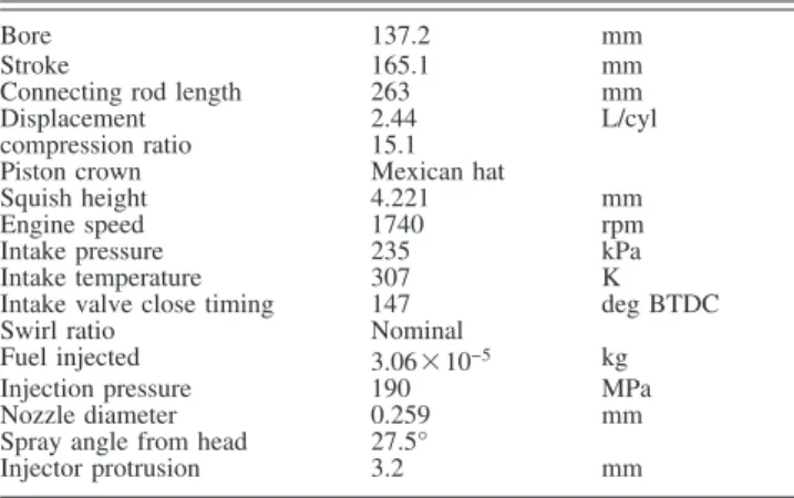
The engine numerically simulated in this study is a single-cylinder version of Caterpillar™ 3400-series 共3406兲 heavy-duty diesel engine. The engine has four valves, a displacement of 2.44 L, electronically controlled fuel injection, and produces 74.6 kW at 1800 rpm. Further details of the engine configuration are summarized in Table 1. This engine has been well character-ized in experimental and computational studies关11–18,41兴.
Experimental measurement of particulate emissions from this engine with and without EGR were carried out by Neill and Chip-pior关42兴. The numerical calculations were conducted under simi-lar conditions to the experiments.
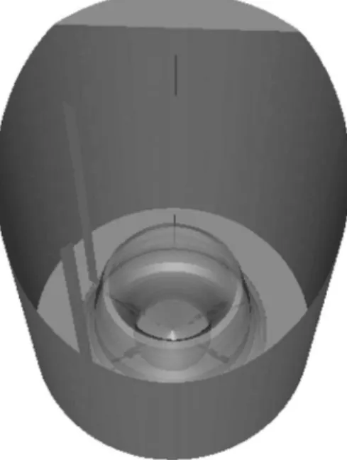
The soot model developed in this study was validated in the calculations of soot emissions from the above-described research engine against experimental data. During the course of this nu-merical study, the engine was not fully equipped and crucial pa-rameters to assess a model in detail, such as cylinder pressure, heat release, injection shape were missing. The AVL test case number seven thus appeared as the easiest one to set-up through a generic approach including: top-hat injection profile, no residual gas, and generic cylinder wall temperature. We are thus primarily interested in generating new information on pollutant formation. Details of the combustion chamber geometry are provided in Fig. 2. Due to the cyclic nature of the configuration around the cylin-der axis, an unstructured mesh of 60° angle sector with a moving piston and containing a single nozzle located on the bisecting plane is simulated.
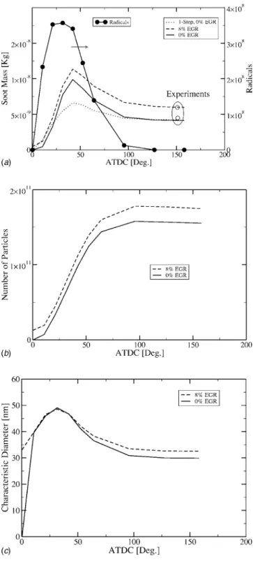
Figure 3 displays the history of the total in-cylinder soot mass 共mtotal兲, total soot particle number 共Ntotal兲, and the characteristic
soot primary particle diameter calculated from sD3/ 6 ⫻ Ntotal
= mtotal. The open circles are the experimental soot emission data
from Ref. 关42兴. The soot emission data in the case of no EGR were used to adjust the value of a0, which is the only parameter that is arbitrarily “tuned” and is expected to be fuel dependent. The one-equation Hiroyasu soot model 关10兴, which has been widely used in diesel engine simulation关1,11–20兴, was also em-ployed in the present calculations using the constants given in Ref.关17兴. Although both the Hiroyasu and the present soot models are capable of predicting the correct trend of the effect of cooled EGR on soot emission, the present model offers insight into the effect of EGR on the soot particle number and size that otherwise cannot be gained in the Hiroyasu model. This is obtained by in-corporating the inception from radicals as well as the heteroge-neous reaction at the surface of the soot particle in a logical se-quence with respect to physical phenomena. For instance, surface reactions clearly allow predicting an increase in the soot diameter 关Fig. 3共c兲兴, in case of EGR. It is noted that the existence of soot particles at TDC in this case is simply due to the re-injection of the soot-containing exhaust gas 共without filter兲 into the intake. Surface reactions are a competition between surface growth, the first term in Eq. 共4兲, and surface oxidation. With EGR, fuel is available for a longer period of time in the cylinder, which favors surface growth关as well as a stronger creation of particles, on Fig. 3共b兲兴 and the temperature is lower, weakening surface oxidation. Furthermore, the incorporation of a step corresponding to the in-duction radicals involves a delay in soot formation关early time in Fig. 3共a兲兴, which is consistent with experiment but is badly rep-resented by the one-step model. This is explained by the low
Table 1 Geometric and physical parameters of the Caterpillar 3400 series diesel engine used in the numerical simulation
Bore 137.2 mm
Stroke 165.1 mm
Connecting rod length 263 mm
Displacement 2.44 L/cyl
compression ratio 15.1 Piston crown Mexican hat
Squish height 4.221 mm
Engine speed 1740 rpm
Intake pressure 235 kPa
Intake temperature 307 K
Intake valve close timing 147 deg BTDC Swirl ratio Nominal
Fuel injected 3.06⫻ 10−5 kg
Injection pressure 190 MPa
Nozzle diameter 0.259 mm
Spray angle from head 27.5°
Injector protrusion 3.2 mm
temperature dependence in the one-step model. The effect of this low temperature dependence may appear of secondary importance regarding the discrepancies induced in the overall soot production, as seen in Fig. 3共a兲. Nevertheless, the underlying consequence is the creation of soot mass in areas of the cylinder where it is physically prevented because the temperature was too low for pyrolysis/inception. Previous studies have demonstrated the im-portance of soot creation dynamics within the volume关8,43,44兴. For instance, in Fig. 4, the soot contour in the median plan of the jet at the end of the injection is given for both models. It is seen that the one-step model predicts that soot is formed very early and close to the injector, a bias already pointed out in Ref.关45兴.
Coagulation is supposed to be weak, as predicted by the present model, Fig. 3共b兲. It has been suspected for two to three decades that the Brownian theory is insufficient to predict coagulation共and also agglomeration兲 in a highly turbulent in-cylinder flow 关46,47兴. However, only few very empirical approaches are currently avail-able.
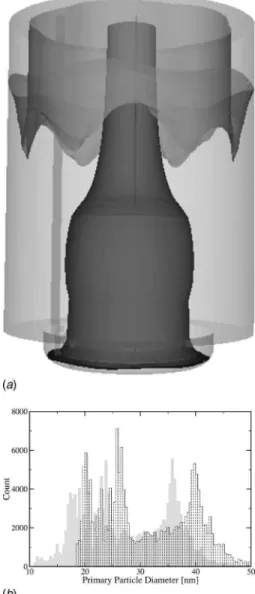
Figure 5 shows the predicted distribution of the primary particle size at the exhaust. This distribution is estimated on a cell by cell basis so that the characteristic diameter Di of the particles con-tained in the cell i is given by
Di=
冉
6ysi
sNi
冊
1/3
共13兲 The weight associated with this diameter is proportional to the number of particles predicted within the cell.
Several observations are to be made. 共i兲 The distribution of primary particle diameter lies in the acknowledged range for the
diesel soot primary particle diameter, i.e., 10– 50 nm. 共ii兲 The overall diameter is increased through EGR, consistent with previ-ous results. 共iii兲 The distribution grossly presents two peaks. These two peaks may be explained by the existence of two soot primary particle populations inside the cylinder. These two popu-lations are depicted in Fig. 5共b兲, where it is seen that soot with diameters below 20 nm共grossly, the left side of the distribution兲 are concentrated in the center of the cylinder and in the bowl while particles with a diameter larger than 40 nm are seen close to
Fig. 2 CFD mesh of the cylinder geometry. Top panel: Full mesh sector „the sector picture has been stretched to show details on the layered part of the mesh subject to connectivity change and squeeze…. Bottom panel: Full cylinder near TDC with spray impingement on the bowl.
Fig. 3 History of the soot formation. „a… Soot mass. „b… Pri-mary particle number. „c… Characteristic diameter. Line: present model. Dots: One-step model. Dashed line: Present model with 8% EGR. Line-circle: Induction radicals. Open circle: Experiment.
the wall, Fig. 5共a兲. Population in the bowl and along the axis is represented by numerous particles of small size and may be re-lated to entities created in the early stages of combustion around the cylinder axis where fuel was available but soot was also oxi-dized in this high-temperature well-mixed zone. Only a small an-nular region关Fig. 6共a兲兴, close to the bowl edge seems to correlate the presence of soot to oxygen depletion as observed in Fig. 7, where the iso-surface in the bowl embeds the volume where the mass fraction of oxygen is below 6%. The other characteristic population is along the wall and the top of the cylinder with re-duced soot oxidation due to heat losses. Their different histories of soot creation dynamics, according to previous explanations, cause soot particles to survive in different regions in the cylinder at the end of the expansion with different implications in soot formation and oxidation, leading to different size distributions and hence the bimodal size distribution found in Fig. 5. However, it should be noted that this distribution is based on primary soot particle size and not on agglomerated clusters effectively gathered at an engine exhaust. The cluster size distribution, not predicted here, may have a different shape.
Conclusion
A soot formation model developed by Tesner et al., already acknowledged for its use in practical applications, has been ex-tended through simple expressions based on kinetic theory. This more comprehensive model is now able to account for an impor-tant part of the soot formation history, to a certain level of ap-proximation, which relies on the limiting step of the pyrolysis, the inception based on active radicals from the hydrocarbon break-down and the growth of the primary particles through collision with each other and the fuel molecules in the surrounding gas. The system of equations is kept as simple as possible to save compu-tational and tuning cost. The intermediate growth specie is by-passed for sake of simplicity, given the numerous approximations encountered at several levels in a real scale 3D simulation. The behavior of this model has been explored with respect to EGR and compared to the one-step model, commonly used by the engine design community. New insights into the soot population history in a diesel engine cylinder have been furthermore gained and ac-tive areas related to soot formation have been pointed out.
This modeling, compatible with engine design tools, reveals some important features of the primary particle history in two main zones in the cylinder, leading to two different populations of soot. Near the bowl edge, the remaining soot is explained by oxygen depletion while, close to the top and the wall, heat losses prevent the destruction of the soot so that much particles exist with a large size. The high-temperature and well mixed interior of the cylinder is populated by small soot particles so that two
char-acteristic primary particle sizes may be encountered at the exhaust 共this size distribution for the primary soot particles should not prevail of the fractal cluster size released at the exhaust兲. EGR leads to an increase in soot mass exhaust through an increase in both the number of primary particles and their diameter. The in-crease in the number of primary particles is related to presence of the fuel for a longer period of time and the increase in diameter may be linked to a weaker oxidation due to lower temperatures in the cylinder.
This soot model is of interest due to its ability to predict the primary particle size. However, the soot structure at the exhaust of an engine is an agglomeration of soot primary particles. Those structures appear following a fractal growth process which deter-mines the final weight, size, and number of those clusters. Predic-tion of agglomeraPredic-tion might be an interesting future development for soot modeling dedicated to diesel engines design. In addition, further validation of the model with experimental data is war-ranted.
Acknowledgment
This research has been made possible by the funding received from the Government of Canada Program for Energy Research
Fig. 5 „a… Picture EGR 0%. Plain iso-surface: Diameter below
20 nm. Transparent iso-surface: Diameter above 40 nm. „b… Par-ticle diameter distribution at the exhaust „Grey: EGR 0%; Dashed: EGR 8%….
Fig. 4 Soot mass fraction distribution in the median plane of the fuel jet at the end of the injection. „a… One-step model. „b… Three-equation model.
and Development共PERD/AFTER兲. The authors wish to thank Dr. S. C. Kong and Professor R. D. Reitz for providing the grid speci-fication of the engine geometry and parameters.
Nomenclature
Only symbols that are either not available or different from those in the international nomenclature of thermal sciences are listed in the nomenclature.
Capital Letters
As ⫽ primary particle surface共m2兲
D ⫽ primary particle diameter共nm兲 F ⫽ branching-termination coefficient共s−1兲
Kc ⫽ coagulation coefficient共m5/2K−1/2s−1兲
KG,incep ⫽ growth coefficient共Kg m3s−1兲
N ⫽ primary particle number density共m−3兲
Tan
o ⫽ fuel pyrolysis activation temperature共K兲
Lowercase Letters
a ⫽ soot inception coefficient共s−1兲
a0 ⫽ preexponential constant of fuel pyrolysis共s−1兲
b ⫽ termination coefficient共m3/ s兲
g0 ⫽ termination coefficient共m3/ s兲
mp ⫽ nominal mass of primary soot particles共kg兲
n ⫽ radical number density共m−3兲
no ⫽ radical production rate共s−1m−3兲
Subscripts F ⫽ fuel species i ⫽ cell number o ⫽ inception s ⫽ soot species References
关1兴 Belardini, P., Bertoli, C., Ciajolo, A., D’Anna, A., and Del Giacomo, N., 1992, “Three Dimensional Calculations of D. I. Diesel Engine Combustion and Comparison With in Cylinder Sampling Valve Data,” SAE Technical Paper No. 92225.
关2兴 U. S. E. P. A. 共EPA兲, 2002, “Air Quality Criteria for Particulate Matter,” Third external review draft EPA/600/P-99/002aC, Research Triangle Park, NC. 关3兴 2001, “Réduire les émissions des Véhicules / Vehicle Emission Reductions,”
92-82-11363-9, Proceedings of the European Conference of Ministers of
Transport (ECMT), OECD, Paris.
关4兴 Khan, G., and Greeves, A., 1974, Method for Calculating the Formation and
Combustion of Soot in Diesel Engines, Scripta, Washington, DC, Chap. 25. 关5兴 Surovikin, V., 1976, “Analytical Description of the Processes of
Nucleus-Formation and Growth of Particles of Carbon Black in the Thermal Decom-position of Aromatic Hydrocarbons in the Gas Phase,” Solid Fuel Chem.,
10共1兲, pp. 92–101.
关6兴 Fusco, A., Knox-Kelecy, A., and Foster, D., 1994, “Application of a Phenom-enological Soot Model to Diesel Engine Combustion,” Proceedings of the International Symposium COMODIA 94, Yokohama, Japan.
关7兴 Appel, J., Bockhorn, H., and Frenklach, M., 2000, “Kinetic Modeling of Soot Formation With Detailed Chemistry and Physics: Laminar Premixed Flames of
Fig. 6 Distribution of the two main soot zones at the end of the simulation. „a… Iso-surface „8.4Ã 10−6… of the soot mass
frac-tion. „b… Iso-surface „1.6Ã 1014kg−1… of the number of primary
particles.
Fig. 7 Oxygen depletion in the bowl. The iso-surface draws a volume in which oxygen mass fraction is below 6%.
C2Hydrocarbons,” Combust. Flame, 121共1/2兲, pp. 122–136.
关8兴 Tao, F., Golovitchev, V., and Chomiak, J., 2004, “A Phenomenological Model for the Prediction of Soot Formation in Diesel Spray Combustion,” Combust. Flame, 136共3兲, pp. 270–282.
关9兴 Ahmad, T., Plee, S., and Myers, J., 1985, “Computation of Nitric Oxide and Soot Emissions from Turbulent Diffusion Flames,” J. Eng. Gas Turbines Power, 107共1兲, pp. 48–53.
关10兴 Hiroyasu, H., and Nishida, K., 1989, “Simplified Three-Dimensional Modeling of Mixture Formation and Combustion in D. I. Diesel Engine,” SAE Technical Paper No. 890269.
关11兴 Patterson, M., Kong, S., Hampson, G., and Reitz, R., 1994, “Modeling the Effects of Fuel Injection Characteristics on Diesel Engine Soot and NOx Emis-sions,” SAE Technical Paper No. 940523.
关12兴 Han, Z., and Reitz, R., 1995, “Turbulence Modeling of Internal Combustion Engines using RNG - Models,” Combust. Sci. Technol., 106共4/6兲, pp. 267– 295.
关13兴 Kong, S., Han, Z., and Reitz, R., 1995, “The Development and Application of a Diesel Ignition and Combustion Model for Multidimensional Engine Simu-lation,” SAE Technical Paper No. 950278.
关14兴 Reitz, R., and Rutland, C., 1995, “Development and Testing of Diesel Engine CFD models,” Prog. Energy Combust. Sci., 21共2兲, pp. 173–196.
关15兴 Uludogan, A., Xin, J., and Reitz, R., 1996, “Exploring the Use of Multiple Injectors and Split Injection to Reduce D. I. Diesel Engine Emissions,” SAE Technical Paper No. 962058.
关16兴 Han, Z., Uludogan, A., Hampson, G., and Reitz, R., 1996, “Mechanism of Soot and NOx Emission Reduction Using Multiple-Injection in a Diesel En-gine,” SAE Technical Paper No. 960633.
关17兴 Chan, M., Das, S., and Reitz, R., 1997, “Modeling Multiple Injection and EGR Effects on Diesel Engine Emissions,” SAE Technical Paper No. 972864. 关18兴 Fuchs, T., and Rutland, C., 1998, “Intake Flow Effects on Combustion and
Emissions in a Diesel Engine,” SAE Technical Paper No. 980508. 关19兴 Das, S., Houtz, P., and Reitz, R., 1999, “Effect of Injection Spray Angle and
Combustion Chamber Geometry on Engine Performance and Emission Char-acteristics of a Large Bore Diesel Engine,” Proceedings of the Spring Techni-cal Conference, ASME, Vol. 32–1, pp. 1–12.
关20兴 Jung, D., and Assanis, D., 2001, “Multi-Zone DI Diesel Spray Combustion Model for Cycle Simulation Studies of Engine Performance and Emissions,” SAE Technical Paper No. 2001-01-1246.
关21兴 Tesner, P., Snegiriova, T., and Knorre, V., 1971, “Kinetics of Dispersed Carbon Formation,” Combust. Flame, 17共2兲, pp. 253–260.
关22兴 Mehler, R., Amann, M., and Schopp, W., 2002, “A Methodology to Estimate Changes in Statistical Life Expectancy Due to the Control of Particulate Mat-ter Air Pollution,” Technical Report No. IR-02-035, InMat-ternational Institute for Applied Systems Analysis, Laxenburg, Austria.
关23兴 Parker, J., 2005, “Air Pollution and Birth Weight among Term Infants in Cali-fornia,” Pediatrics, 115共1兲, pp. 121–128.
关24兴 Lee, J., Goto, Y., and Okada, M., 2002, “Measurement of the Diesel Exhaust Particle Reduction Effect and Particle Size Distribution in a Transient Cycle Mode With an Installed Diesel Particulate Filter共DPF兲,” SAE Technical Paper No. 2002-01-1005.
关25兴 Moss, J., Stewart, C., and Young, K., 1995, “Modeling Soot Formation and Burnout in a High Temperature Laminar Diffusion Flame Burning under Oxygen-Enriched Conditions,” Combust. Flame, 101共4兲, pp. 491–500. 关26兴 Leung, K., Lindstedt, R., and Jones, W., 1991, “A Simplified Reaction
Mecha-nism for Soot Formation in Nonpremixed Flames,” Combust. Flame, 87共3/4兲, pp. 289–305.
关27兴 Bédat, B., Egolfopoulos, F. N., and Poinsot, T., 1999, “Direct Numerical
Simu-lation of Heat Release and NOx Formation in Turbulent Nonpremixed
Flames,” Combust. Flame, 119共1/2兲, pp. 69–83.
关28兴 Nagle, J., and Strickland-Constable, R., 1962, “Oxidation of Carbon Between 1000– 2000° C,” Proceedings of the Fifth Conference on Carbon, Pergamon, London, pp. 154–164.
关29兴 Fenimore, C., and Jones, G., 1967, “Oxidation of Soot by Hydroxyl Radicals,” J. Phys. Chem., 71共3兲, pp. 593–597.
关30兴 Bradley, D., Dixon-Lewis, G., El-Din Habik, S., and Mushi, E., 1984, “The Oxidation of Graphite Powder in Flame Reaction Zones,” Proceedings of the
20th International Symposium on Combustion, The Combustion Institute, Pittsburgh, pp. 931–940.
关31兴 Garo, A., 2004, private communication.
关32兴 Westbrook, C., and Dryer, F., 1984, “Chemical Kinetic Modelling of Hydro-carbon Combustion,” Prog. Energy Combust. Sci., 10共1兲, pp. 1–57. 关33兴 Magnussen, B., and Hjertager, B., 1976, “On Mathematical Modeling of
Tur-bulent Combustion With Special Emphasis on Soot Formation and Combus-tion,” Proceedings of the 16th International Symposium on Combustion, The Combustion Institute, Pittsburgh, pp. 719–729.
关34兴 Methodology volume, Star-CD, 2004, Edition.
关35兴 Huh, K., and Gosman, A., 1991, “A Phenomenological Model of Diesel Spray Atomisation,” Proceedings of the International Conference on Multiphase Flows共ICMF’91兲, Tsukuba, Japan.
关36兴 Reitz, R., and Diwakar, R., 1986, “Effect of Drop Breakup on Fuel Sprays,” SAE Technical Paper No. 860469.
关37兴 Mastorakos, E., and Wright, Y. M., 2003, “Simulations of Turbulent Spray Auto-Ignition With Elliptic Conditional Moment Closure,” Proceedings of the European Combustion Meeting, Orléans, France.
关38兴 Yakhot, V., Orszag, S., Thangam, S., Gatski, T., and Speziale, C., 1992, “De-velopment of Turbulence Models for Shear Flows by a Double Expansion Technique,” Phys. Fluids A, 4共7兲, pp. 1510–1520.
关39兴 Launder, B., and Spalding, D., 1974, “The Numerical Computation of Turbu-lent Flows,” Comput. Methods Appl. Mech. Eng., 3共2兲, pp. 269–289. 关40兴 Jayatilleka, C., 1969, “The Influence of Prandtl Number and Surface
Rough-ness on the Resistance of the Laminar Sub-Layer to Momentum and Heat Transfer,” Prog. Heat Mass Transfer, 1, pp. 193–330.
关41兴 McLandress, A., Emerson, R., McDowell, P., and Rutland, C., 1996, “Intake and in-Cylinder Flow Modeling Characterization of Mixing and Comparison With Flow Bench Results,” SAE Technical Paper No. 960635.
关42兴 Neill, W. S., and Chippior, W., 2002, NRC Report No. PET-1528-02S. 关43兴 Hergart, C., Barths, H., and Peters, N., 2000, “Using Representative Interactive
Flamelets in Three-Dimensional Modelling of the Diesel Combustion Process Including Effects of Heat Transfer,” Proceedings of the International Multidi-mensional Engine Modeling User’s Group Meeting, Madison, WI. 关44兴 Hergart, C., and Peters, N., 2002, “Applying the Representative Interactive
Flamelet Model to Evaluate the Potential Effect of Wall Heat Transfer on Soot Emissions in a Small-Bore Direct-Injection Diesel Engine,” J. Eng. Gas Tur-bines Power, 124共4兲, pp. 1042–1052.
关45兴 Tao, F., Srinivas, S., Reitz, R. D., and Foster, D. E., 2004, “Current Status of Soot Modeling Applied to Diesel Combustion Simulations,” Proceedings of the International Symposium COMODIA 2004, Yokohama, Japan. 关46兴 Khan, I. M., Wang, C. H. T., and Langridge, B. E., 1971, “Coagulation and
Combustion of Soot Particles in Diesel Engines,” Combust. Flame, 17共3兲, pp. 408–419.
关47兴 Smith, O. I., 1981, “Fundamentals of Soot Formation in Flames With Appli-cation to Diesel Engine Particulate Emissions,” Prog. Energy Combust. Sci.,
7共4兲, pp. 275–291.