HAL Id: tel-02275816
https://tel.archives-ouvertes.fr/tel-02275816
Submitted on 2 Sep 2019HAL is a multi-disciplinary open access archive for the deposit and dissemination of sci-entific research documents, whether they are pub-lished or not. The documents may come from teaching and research institutions in France or abroad, or from public or private research centers.
L’archive ouverte pluridisciplinaire HAL, est destinée au dépôt et à la diffusion de documents scientifiques de niveau recherche, publiés ou non, émanant des établissements d’enseignement et de recherche français ou étrangers, des laboratoires publics ou privés.
energy storage elements for aeronautical usage
Yuanci Zhang
To cite this version:
Yuanci Zhang. Performance and ageing quantification of electrochemical energy storage elements for aeronautical usage. Electronics. Université de Bordeaux, 2019. English. �NNT : 2019BORD0029�. �tel-02275816�
THÈSE PRÉSENTÉE
POUR OBTENIR LE GRADE DE
DOCTEUR DE
L’UNIVERSITÉ DE BORDEAUX
ÉCOLE DOCTORALE SCIENCES PHYSIQUES ET DE L’INGÉNIEUR SPÉCIALITÉ ÉLECTRONIQUE
par
Yuanci ZHANG
Performance and ageing quantification of
electrochemical energy storage elements for aeronautical usage
Sous la direction de : Jean-Michel VINASSA Co-direction : Olivier BRIAT
Soutenue le 15/03/2019
Membres du jury :
Corinne ALONSO, Professeur à l’Université de Toulouse III Paul Sabatier, LAAS Présidente Christophe FORGEZ, Professeur à l’Université de Technologie de Compiègne, LEC Rapporteur Pascal VENET, Professeur à l’Université de Lyon 1, Ampère Rapporteur Delphine RIU, Professeur à Grenoble INP, G2Elab Examinatrice Loïc BOULON, Professeur à l’Université du Québec à Trois-Rivières, IRH Examinateur
Remerciements
Ce manuscrit résume trois ans d’aventures inoubliables passées au Laboratoire de l’Intégration du Matériau au Système (IMS) au sein de l’équipe Puissance du groupe Fiabilité. Je ne pourrais pas commencer la présentation de ce mémoire sans remercier toutes les personnes ayants contribué de près ou de loin à mes travaux de thèse.
Je remercie en premier lieu Monsieur Yann Deval, directeur de l’IMS, ainsi que Mme Geneviève Duchamp responsable du groupe Fiabilité. Je remercie également l’IRT Saint Exupéry d’avoir financé ma thèse et de m’avoir fourni les moyens pour réaliser mes travaux de recherche dans les meilleures conditions. Je remercie Madame Régine Sutra-Orus, directrice du département Aéronef Plus Electrique à l’IRT, Monsieur Fabio Coccetti, responsable du pôle fiabilité et modélisation à l’IRT et Monsieur Guillaume Gager, chef de projet CELIA, pour leur soutien et leurs qualités humaines. Je remercie également les membres industriel de Safran Tech, Zodiac Aerospace et Airbus pour nos échanges intéressants lors de chaque réunion.
Je remercie vivement le Professeur Corinne Alonso d’avoir présidé le jury, son côté humain m’a impresionnée. Je suis honorée que le Professeur Pascal Venet et le Professeur Christophe Forgez aient accepté de rapporter ma thèse. Je les remercie énormément pour l’intérêt qu’ils ont porté à mon travail et pour les remarques constructives et pertinentes quant aux perspectives de mes travaux. Je remercie également le Professeur Delphine Riu et le Professeur Loïc Boulon d’avoir pris un temps précieux pour examiner et évaluer mes travaux.
Un merci infini au Professeur Jean-Michel Vinassa (mon ShiFu) d’avoir dirigé ma thèse. La patience de Jean-Michel pour initier les électroniciens, comme c’est mon cas, à l’électrochimie m’a été vraiment précieuse. La rigueur de Jean-Michel m’a permis de poser et creuser les points douteux que j’ai pu rencontrer durant mes travaux. Ses apports scientifiques m’ont toujours permis d’avancer à un niveau plus haut. De plus, sa franchise facilite les échanges quotidien. Je tiens à remercier chaleureusement mon co-directeur, le Maitre de Conférence HDR Olivier Briat pour son suivi quotidien, ses aides sur les logiciels de simulation, ses conseils sur les essais de vieillissement et ses corrections d’articles qui m’ont permis d’apprendre et de juger les travaux de manière réfléchie et critique. Un grand merci à tous les deux pour leur encadrement attentif et pédagogique qui m’a permis de réaliser ma thèse dans des conditions très favorables !
Je ne remercierai jamais assez PhD Jean-Yves Delétage pour son aide, sa disponibilité, ses conseils sur l’utilisation des équipements et son efficacité à intervenir dans la plateforme afin de dépanner les enceintes, les machines virtuelles, les logiciels de simulation durant ces trois années de thèse. Je remercie également Monsieur Cyril Martin pour tous ses excellents check-up, sa disponibilité pour lancer les essais à l’heure et son temps consacré à tous les essais de vieillissement. Je n’aurais pas pu finaliser ma thèse à temps sans vous deux !
Je remercie maintenant pour tout Issam, le grand frère de l’équipe puissance-batterie. Il est toujours souriant et il nous soutient sur les questions scientifiques et personnelles. Romain pour son support technique sur Matlab (Roi de Matlab), et les discussions autour de la modélisation des batteries. Matthieu est toujours disponible pour résoudre des équations mathématiques complexes ou pour discuter sur des sujets innovants. Et bien sûr, les deux filles : Armande et Laurine qui sont arrivées lors de ma dernière année de thèse, j’ai pu discuter de sujets entre filles, enfin ! Merci à Faïçal pour sa lecture du premier chapitre. Merci Guillaume, Isabelle, Ounuma, Simon, Jean-Baptiste, Mingming et Quentin. Merci pour tous les bons moments, les fous rires, les bons bars, les bons plats et les soirées Karaoké ! Merci aussi à toutes les personnes que j’ai côtoyé à l’IMS durant ces trois années : Thomas, Nicolas, Emmanuel, Miguel, Florent, Omar, Mohamed, Pierre, Florent, Maxime, Antoine, Toni, Aurore et Mickael.
Merci aussi à toutes les personnes extérieures au laboratoire. Corinne et Philippe pour vos disponibilités. Les moments que j’ai passé avec Xiaotong, Ming, Rui, Hui et Wen, Zheng au travers de bons plats et de bon vin m’a redonné des forces. Merci à mes trois meilleurs amis ingénieurs de PHELMA : Zélie, Marjorie et Blandine pour tout ce que vous faites !
Pour finir, je dédie également cette thèse à mon copain Johan Guerrier et sa famille, qui ont toujours été présents pour m’encourager tout au long de ces années de thèse, sans oublier mes parents qui m’ont beaucoup soutenu depuis que je suis arrivée en France. Pour terminer, je réserve une pensée toute particulière à la mémoire de ma grand-mère Lanying. Elle m’a proposé de faire un PhD depuis que j’étais petite. Chacun d’entre vous m’a permis d’accomplir l’ensemble de ce travail dans de très bonnes conditions.
Table of contents
Table of contents ...i
General introduction ... 5
Chapter 1 State of art for electrochemical energy storage systems and aeronautical applications ... 9
1.1 Introduction ... 10
1.2 Electrochemical energy storage systems ... 10
1.2.1. The working principle of LiBs ... 12
1.2.2. The variety of Li-ion technologies ... 12
1.2.3. Form of LiBs ... 15
1.2.4. The working principle of SCaps... 16
1.2.5. The working principle of LiCs ... 17
1.3 Characteristic of LiBs, SCaps and LiCs with characterization methods ... 18
1.3.1. Open Circuit Voltage ... 19
1.3.2. Internal resistance or ESR ... 21
1.3.3. Impedance ... 22
1.3.4. Capacity or capacitance ... 22
1.3.5. State of charge ... 23
1.3.6. Energy or power density ... 23
1.4 Electrochemical energy storage systems for aeronautical applications ... 24
1.4.1. Electrochemical energy storage systems used in aircraft ... 24
1.4.2. Energy and power requirements in more electrical aircraft ... 25
1.4.3. Issues of electrochemical energy storage elements for aeronautical usage .... 26
1.4.3.1 Gap between technologies of electrochemical energy storage and electrical energy requirements in aircraft ... 26
1.4.3.2 Issues related to aeronautical conditions ... 28
1.4.4. Standards and certifications ... 29
2.1 Introduction ... 32
2.2 Experiments ... 32
2.2.1. Tested technologies of LiBs, SCaps, LiCs and Li-S ... 32
2.2.2. The CaCySSEE platform ... 35
2.3 Reference test design ... 36
2.3.1. Reception tests ... 36
2.3.2. Initial tests ... 36
2.3.3. Performance tests ... 37
2.3.3.1 Incremental discharge ... 37
2.3.3.2 Available discharged capacity ... 38
2.3.3.3 Maximal power discharge ... 38
2.3.4. Ageing tests ... 39
2.3.5. Abuse tests ... 39
2.3.6. Available discharged capacity for LiBs, LiCs and SCaps ... 39
2.4 Cell to cell characterization ... 41
2.5 Non-isothermal Ragone plots of 18650 Li-ion cells from datasheet and galvanostatic discharge tests ... 41
2.5.1. Performance quantification with experimental approach ... 42
2.5.2. Comparison for constant current discharge ... 43
2.5.3. Performance quantification with Ragone plot model ... 45
2.5.3.1 Electrical model ... 46
2.5.3.2 Thermal model ... 50
2.5.4. Validation of Ragone Plot model ... 53
2.5.4.1 Ragone plot model for 25°C ... 54
2.5.5. Extending Ragone plot model for wide operating temperature range ... 56
2.5.6. Enhanced non-isothermal Ragone plot ... 58
2.6 Conclusion ... 59
Chapter 3 Ageing study of electrochemical energy storage elements ... 61
3.1 Introduction ... 62
3.2 Overview of ageing mechanisms in electrochemical energy storage elements ... 62
3.2.1. Ageing mechanisms in LiBs ... 63
3.2.1.1 SEI formation ... 63
Table of contents
3.2.1.3 Dissolution of transition-based materials ... 65
3.2.1.4 Other ageing mechanisms ... 65
3.2.2. Ageing mechanisms in SCaps and LiCs ... 65
3.3 Impact of ageing mechanisms on performance and security ... 66
3.4 Ageing types definition ... 69
3.4.1. Calendar ageing tests ... 69
3.4.2. Power cycling ageing ... 69
3.5 Ageing test experiments ... 69
3.5.1. Characteristics of calendar ageing tests ... 70
3.5.2. Characteristics of power cycling ageing tests ... 70
3.5.3. Check-up protocols ... 71
3.6 Calendar ageing results and analyses ... 73
3.6.1. Raw tests results ... 73
3.6.2. Capacity loss analyses under calendar ageing in a wide temperature range ... 76
3.7 Power cycling ageing results and analyses ... 81
3.8 Abuse tests and results ... 87
3.8.1. Thermal stability test ... 87
3.8.2. Overcharge test ... 89
3.8.3. Altitude simulation test ... 91
3.9 Comparison of different electrochemical energy storage elements ... 92
3.10 Conclusion ... 94
Chapter 4 SOH estimation of electrochemical energy storage elements ... 97
4.1 Introduction ... 97
4.2 Overview of SOH estimation methods ... 98
4.2.1. Experimental methods ... 99
4.2.2. Model-based estimation methods ... 99
4.3 Principles of Incremental Capacity Analysis ... 100
4.4 Raw tests results for qualitative and quantitative ICA study... 101
4.5 Enhanced IC by moving average filter ... 102
4.6.3. Decomposition of IC curves based on Gaussian Lorentzian mixed function107 4.6.4. Peak features with respect to normalized capacity and normalized resistance108
4.6.5. Method validation for cells with unknown SOH ... 110
4.7 Conclusion ... 112
Chapter 5 Experiments and modelling of accelerated ageing with a specific aeronautical profile ... 115
5.1 Introduction ... 115
5.2 Design of the accelerated ageing tests ... 115
5.2.1. Proposed aeronautical profile ... 116
5.2.2. Characteristics of accelerated ageing tests ... 118
5.3 Experiments and raw results ... 119
5.4 Ageing modelling and SOH estimation ... 121
5.4.1. Temperature effects on the degradation rate of capacity ... 121
5.4.2. SOH estimation ... 123
5.4.2.1 Qualitative and quantitative ICA ... 123
5.4.2.2 Validation of the proposed method ... 126
5.5 Conclusion ... 127
General conclusion ... 129
Table of figures ... 133
References ... 137
General introduction
Despite the global aviation sector produces only around 2% of anthropogenic Carbon Dioxide (CO2) emissions, the growth of the airline is significant thanks to the globalization [1].
If left to continue at the current pace, the CO2 emission of aviation could reach 10% by the
middle of the century [2]. Besides the CO2 emissions, the non-CO2 emissions such as nitrogen
oxide (NOx), sulphur oxides (SOx), hydrocarbons (HC) and black carbon particles emitted by
aviation can cause a variety of environmental effects. Therefore, the Air Transport Action Group (ATAG) decided to introduce a regulatory framework to reduce aviation’s emission in 2016 [1] [3]. An ambitious targets to mitigate the net aviation CO2 emissions of 50% by 2050
compared to 2005 levels.
It is becoming increasingly clear that progress on engine and aircraft architecture are necessary but not sufficient to achieve this objective [2]. Hence, the growing interest is in electrification, which has the advantage of reducing dependence on fossil fuels, reducing CO2
emissions and noises, making flight safer. As illustrated in Figure 0-1, the electrical power generating capacity has a significant growth in the last 20 years, especially for Boeing 787. In spite of the more electrical aircraft (MEA) represents multiple advantages compared to the conventional aircraft, the introduction of MEA leads to some new challenges concerning the technology, the efficient electrical systems, effective systems intergradation. The air companies around the world are working on these topics.
Figure 0-1 Electrical power generating capacity vs. introduction year [4]
at minimum of 500Wh/kg for all-electric and hybrid aircraft. However, the energy density range of current commercial batteries is from 150-250Wh/kg, therefore, a technology gap is still crucial. Due to the accident of Li-ion battery failure in Boeing 787 (Figure 0-2) [5], the development of MEA must take into account these essential issues in order to integrate the electrochemical energy storage elements in the aircraft.
Figure 0-2 Li-ion battery of Boeing 787 Dreamliner airline before and after accident [5]
In this context, “CELIA” project has been conducted, which is supported by the Institute of Technology Saint-Exupéry and funded by the French National Research Agency. This project has several industrial partners: Zodiac Aerospace, Safran Tech, Airbus and academic laboratories: IMS-Bordeaux and LRCS-Amiens. The main objectives of this project are listed below.
For the short term:
• To promote the emergence of electrochemical energy storage technologies for aeronautical usage.
• To develop efficient methods to evaluate the commercial electrochemical energy storage elements for aeronautical applications.
• To deep understand the performance and ageing behaviours of different electrochemical energy storage types, including Li-ion cells, Supercapacitors (SCaps), Li-ion capacitors (LiCs) in aeronautical environment (extreme temperature, low pressure)
• To investigate models or tools to evaluate or estimate the reliability, the robustness and to identify the failure modes of electrochemical energy storage elements.
For the long term:
• To develop the new technologies to meet the energy and power needs for more electrical aircraft.
• To evaluate the practical energy density of Li-air technology, versus the theoretical energy density of 1300Wh/kg.
General introduction
The thesis work presented in this manuscript and realized in IMS Laboratory, which is based on the framework of “CELIA” project and focused on the objectives for short term in particular. Nowadays, facing the diversity electrochemical energy storage elements provided by manufacturers, there is no specific reference tests to evaluate their performance, reliability and robustness during operation in the aeronautical environment. There is also a lack of knowledge about electrochemical energy storage elements behaviors under the abuse conditions in the case of dysfunction, such as thermal runaway, overcharge and under low pressure. Furthermore, no study was investigated on the coupling between ageing factors and an accelerated ageing laws relating to a specific profile for aeronautical usage.
In order to achieve these objectives, this manuscript is composed of five chapters. The chapter 1 is focused on an overview of diversity electrochemical energy storage elements and their applications for aeronautical usage. The working principle of Li-ion batteries, Supercapacitors and Li-ion capacitors are presented throughout their characteristic with multiple characterization methods. Then, the electrochemical energy storage elements used in aircraft are introduced. Finally, the essential challenges for aeronautical usage are listed.
The chapter 2 concerns the comparative performance quantification by experiments and modelling. Nine technologies of the latest generation of commercial elements are investigated in this thesis, including Li-ion cells (NMC/graphite + SiO, NCA/graphite, LFP/graphite, NMC/LTO), Lithium-Sulfur (Li-S), SCpas and LiCs. A reference tests taking into account the aeronautical environment and usage is proposed. In addition, an efficient electrical–thermal model is established in order to build a Ragone plot to quantify the energy density and power density for electrochemical energy storage elements.
The chapter 3 is devoted to the study of robustness and safety for investigated electrochemical energy storage elements. For this, calendar ageing and power cycling ageing as well as a synthesis of abuse tests results are investigated in the aeronautical environment. A summary of performance evaluation according to seven criteria (energy density, power density, available capacity at extreme temperatures, lifetime in calendar ageing type, self-discharge, number of cycles and safety) is proposed in order to select the most promising commercial electrochemical energy storage elements.
The results of the various periodic characterization throughout the calendar ageing and power cycling ageing tests in chapter 3 are used in the chapter 4 to investigate a SOH estimation for Li-ion cells. This method is based on qualitative and quantitative Incremental Capacity Analysis (ICA), which is able to identify the degradation modes during ageing tests, to estimate which ageing types Li-ion cells historically underwent and the internal resistance evolution.
The chapter 5 is dedicated to the evaluation of robustness for electrochemical energy storage elements in the accelerated ageing tests with a specific aeronautical profile. Only the most promising technologies of Li-ion are retained in this chapter. Thus, a specific aeronautical profile is proposed, which corresponds to a series of flight phases for an air travel in metropolitan France. The ageing models and SOH estimation methods proposed in the previous
Chapter 1
State of art for electrochemical energy storage
systems and aeronautical applications
Table of contents
1.1 Introduction ... 10
1.2 Electrochemical energy storage systems ... 10
1.2.1. The working principle of LiBs ... 12
1.2.2. The variety of Li-ion technologies ... 12
1.2.3. Form of LiBs ... 15
1.2.4. The working principle of SCaps... 16
1.2.5. The working principle of LiCs ... 17
1.3 Characteristic of LiBs, SCaps and LiCs with characterization methods ... 18
1.3.1. Open Circuit Voltage ... 19
1.3.2. Internal resistance or ESR ... 21
1.3.3. Impedance ... 22
1.3.4. Capacity or capacitance ... 22
1.3.5. State of charge ... 23
1.3.6. Energy or power density ... 23
1.4 Electrochemical energy storage systems for aeronautical applications ... 24
1.4.1. Electrochemical energy storage systems used in aircraft ... 24
1.4.2. Energy and power requirements in more electrical aircraft ... 25
1.4.3. Issues of electrochemical energy storage elements for aeronautical usage .... 26
1.4.3.1 Gap between technologies of electrochemical energy storage and electrical energy requirements in aircraft ... 26
1.1 Introduction
Over the last twenty years, global demand for energy is rising with overcrowding. Transport plays a significant role in human activities. Almost all transportation are powered by petroleum fuels. However, the combustion products of petroleum are the main pollutants emitted in the environment, which affects air quality and causes damage to human health. Therefore, numerous studies have been dedicated to finding other alternative fuels or enhancing the sustainability and reliability of energy storage systems in order to decrease fuel consumption, produce less CO2 emissions and polluting gas [6]. Among the various choices of
energy storage systems, the electrochemical energy storage systems above all offer several advantages. Lithium-ion batteries are integrated in the vehicle to meet the power and energy requirements with less CO2 emissions. While, using the electrochemical storage systems
becomes one of the hindrance to electrification of aircraft.
This first chapter is composed of two major sections. In the first section, the various electrochemical energy storage systems are presented and compared throughout their working principles and their characteristics. In particular for the Lithium-ion batteries (LiBs), the Supercapacitors (SCaps) and the Lithium-ion Capacitors (LiCs). The second section is devoted to present in details a state of art on the electrochemical energy storage systems for aeronautical usages. Furthermore, some issues about aeronautical environment and security of electrochemical energy storage systems are discussed. Finally, the standards and the certifications of LiBs and SCaps are listed, which are considered as a reference test to quantify and compare the performance of LiBs and SCaps in the future study.
1.2 Electrochemical energy storage systems
In order to reduce the dependence of fossil fuels, renewable energy is an alternative solution to complete other energies. In 2016, renewable sources (hydropower, biomass, wind, solar, geothermal) account for approximately 26% of global electricity [7]. However, most of the renewable energy sources are intermittent. The Electrical Storage Systems (ESSs) is one of the few ways to store and use electricity later [8]. The electrochemical storage system is one of the most used SSE in everyday life and industrial [9], such as the LiBs or SCaps used in the portable application (mobile phone, laptop, tablet, tools), or in the transport sector where the electrification of vehicles or airplanes, is gradually growing.
The electrochemical storage system converts chemical energy into electrical one and vice versa. Energy density and power density are the two commonly used indexes for quantifying the performance of electrochemical storage systems [10]. The energy density represents the energy that electrochemical storage systems can be stored/delivered per unit mass. While, the power density represents at which speed this energy can be stored/delivered.
In general, the Ragone plan allows to compare different ESSs. As illustrated in Figure 1-1 the different SSEs are positioned according to the characteristics between the energy density (Wh/kg) and the power density (W/kg). The fuel cell is located at the top left of this plan, it is therefore intended for energy applications. On the contrary, conventional capacitors are used for high power applications. The lines that cross this plan are the time constants, defined by the ratio of energy / power, which corresponds to the time required to fill/empty the storage system.
Electrochemical energy storage systems
Figure 1-1 Ragone diagram of the main electrochemical energy storage elements
In this Ragone diagram, the electrochemical storage elements are positioned between the fuel cell and the conventional capacitor. In general, they can be classified into two major families: batteries and SCaps. The differences between them are related to the ways of storing electric charges.
For batteries, electrical energy is stored in the bulk electrode. As illustrated in the Figure 1-2, the intercalation/de-intercalation of Li+ allows to have oxidation-reduction reactions of the electrode materials in the case of LiBs. This reaction type is accompanied with the charge transfer, which is also called faradic charge storage. The electrochemical reaction is controlled by the slow diffusion phenomenon [8]. Batteries are therefore considered as energetic elements.
On the contrary, in the case of SCaps, the electric charge is stored by ions adsorption in the electrolyte on the electrode surface. The reaction occurs fast without material transport, the SCaps are intended for power applications [11]. In addition, the LiCs mentioned in the Ragone plan combine energy and power.
The following paragraphs present individually the compositions and the working principles of the different technologies located in each family, in particular for LiBs, LiCs and SCaps.
1.2.1 The working principle of LiBs
Figure 1-3 represents the main working principle of a lithium-ion cell. A lithium-ion cell consists of two electrodes: positive and negative. Positive electrode are composed by Li metal oxide materials. While, graphite is the most common material used for negative electrode. The potential between two electrodes gives the cell voltage, which depends on the chemistry of the electrode materials and operating conditions. These two electrodes are connected to the external circuit by current collectors. In general, current collectors are made of aluminium for the positive electrode and copper for the negative one. These two electrodes are bathed in an electrolyte that is liquid, solid or gel. A porous separator is located between these two electrodes to avoid the short circuit.
The working principle of a lithium-ion cell is based on the intercalation/de-intercalation of Li+ into the electrode materials. During the discharge, the Li+ are removed from the graphite negative electrode (anode), they migrate into the electrolyte and then pass through the separator and insert into the positive electrode (cathode). At the same time, the charge transfer takes place on the electrode-electrolyte interface, the current is therefore created. During the charge, the displacement of Li+ is opposite.
Figure 1-3 Working principle of Li-ion cell
1.2.2 The variety of Li-ion technologies
To meet the needs in terms of energy, power and price requirements for application, there are multiple lithium-ion technologies. They are distinguished by the materials used in the lithium-ion cell. However, their working principle is always based on the intercalation and the de-intercalation of Li+.
Electrochemical energy storage systems
• Negative electrode
The main materials used in the negative electrode of LiBs are summarized in Table 1-1. The characteristics are referred by the review of Goriparti et al. [12].
Family Abbreviation Potential vs. Li+/Li (V) Theoretical capacity (mAh/g) Lithium-metal Li 0 3862 Carbon materials (Graphite) LiC6 0.02-0.3 372 X alloy (X: Si, Ge, SiO)
LiX 0.3-0.4 1000-3500
Titanate (Li4Ti5O12)
LTO 1.5 175
Table 1-1 Main materials of negative electrode used in LiBs [12] [13]
The first material used for the negative electrode is pure lithium thanks to its low weight, which allows to cells have a significant energy and power density. However, pure lithium-metal remains a very active element in contact with oxygen and water. In addition, the metal deposition of lithium can generate the internal short circuit during the cell operation, which introduces security issues.
Lithium metal is therefore replaced by carbon materials. Graphite is the most used material for the negative electrodes of LiBs compared to other materials because of its chemical and thermal stability and good reversibility during intercalation/de-intercalation reaction. In addition, this material is abundant and less expensive. Graphite has a layered, planar structure. Non-compact hexagonal layers are separated with a distance of 0.335nm. In each layer, 6 carbon atoms are strongly linked to each other by strong covalent bonds [12]. Bonding between layers is via weak Van der Waals bonds, which facilitates the intercalation and de-intercalation of lithium ions between each layer. Its potential is rather low and converges to that of lithium-metal. However, the theoretical capacity of graphite is a little weak.
The alloys that are often used in the negative electrodes have a high theoretical capacity compared to graphite. However, the main problem is that the silicon particle size increases during intercalation of Li+, this causes an expansion of the negative electrode [12]. As a result,
the cycle life of LiBs is limited.
• Positive electrode
Currently, the materials used for the positive electrode are multiple. This type of material, called “host materials”, should be in a lithiated form. They are divided into three large families according to their crystalline structure. The main materials used in the positive electrode of LiBs are listed in Table 1-2.
LCO, NCA and NMC belong to the laminar oxide family. LiCoO2 was the first material used for the positive electrode, it is still adapted to today's needs thanks to its high energy density [14]. Its cost and thermal instability because of cobalt presence remain the biggest disadvantages. To make LCO more stable, progress have been done thanks to the addition of materials such as nickel, manganese and aluminium. NCA and NMC are therefore widely used in commercial LiBs.
Family Material Abbreviation
Potential vs. Li+/Li (V) Theoretical capacity (mAh/g) Laminar oxide LiCoO2 LiNi0.8Co0.15Al0.05O2 LiNi1/3Mn1/3Co1/3O2 LCO NCA NMC 4 4 4 274 279 280
Spinel oxide LiMn2O4 LMO 4 148
Olivine
phosphate LiFePO4 LFP 3.5 170
Sulfur Li2S8 Li-S 2 1672
Table 1-2 Main materials of positive electrode used inLiBs [13] [14]
LMO is considered as an element of spinel materials family for positive electrode. Its three-dimensional structure increases the availability of Li+ insertion. The diffusion of Li+ is therefore taking place faster. However, it remains unstable at high temperature, the manganese in positive electrode can be dissolved in the electrolyte[15].
Goodenough synthesized LiFePO4 for the positive electrode material. Its structure called
"Olivine”. Iron is an abundant and non-toxic material. In addition, LiFePO4 has a good thermal
stability. However, its low potential leads to a low energy density.
Li-S is an interesting candidate for the positive electrode material due to its high specific capacity, which can be reached 8 to 10 times higher than other materials of positive electrode. Despite this strong point, there are two manufacturers commercialize this technology. There are still some hindrances to overcome, such as strong self-discharge and low lifetime [16].
• Electrolyte
The electrolyte assures the Li+ transfer between two electrodes. The electrolytes used in LiBs are often classified into two groups: the liquid electrolyte and the solid or gelled electrolyte [17]. The liquid electrolyte consists of soluble lithium salts, such as hexafluorophosphate of
Electrochemical energy storage systems
lithium (LiPF6) in organic solvents as Ethylene Carbonate (EC), Propylene Carbonate (PC) or
Methyl Ethyl Carbonate (MEC). For the solid or gelled electrolyte, the lithium salts are incorporated into the polymer matrix. Then, they are shaped into a film or gel. For all types of electrolytes, they must be a good ionic conductor. Furthermore, they must have good electrochemical and thermal stability over a wide range of voltage and temperature to prevent its decomposition [13].
• Separator
The role of the separator is to separate the two electrodes and to provide the ionic conductivity needed during LiBs working. The separator is made of a polymer membrane of a few tens of micrometres in thickness. Polyethylene (PE) and Polypropylene (PP) are often used as separator material with a porous structure [18]. PP ensures the mechanical strength thus making the LiBs more safe thanks to its low melting point. Separators with a sandwich structure (PP/PE/PP) are also found in LiBs [19]. This three-layer structure can operate as a switch when the battery is overloaded.
1.2.3 Form of LiBs
A lithium-ion battery consists of several cells in series to increase its terminal voltage or in parallel to improve its current range. To choose a specific technology of LiBs, apart from the materials used in the cell, assembly of cell is very important. The latter depends on the form of cell. Figure 1-4 illustrates the three different forms of the lithium-ion cells: cylindrical, prismatic and pouch forms.
Figure 1-4 Different forms of Li-ion cell (a) Cylindrical, (b) Prismatic, (c) Pouch [20]
The cylindrical cells follow a standard size model, such as 18650 or 26650. For the 18650 cell, it has 18mm in diameter and 65mm in height. The same definition for 26650. The cylindrical cell is based on the superposition of layers in anode-separator-cathode. This arrangement makes it possible to increase the surface of active materials in electrodes. Then, these layers are wound around a central pivot and spooled on several turns, finally the whole is installed in a steel compartment and impregnated in the electrolyte [21]. Moreover, a valve
The cell in pouch form is the most recent design. Multiple positive electrodes-separators-negative electrodes are stacked and enclosed in a plasticized aluminium film envelope, which makes the cells lighter and more flexible. However, this flexible envelope can produce the cell swelling because of the gas generated by the decomposition of the electrolyte [23].
1.2.4 The working principle of SCaps
The SCaps consist of two activated carbon electrodes that are separated by a porous membrane. The whole is impregnated into electrolyte as shown in Figure 1-5.
Both porous electrodes based on activated carbon have a high specific surface area (typically 2000m2g-1) [8]. Mastering the porosity and the pore diameter are predominant in the carbon activation process, since they are directly related to the kinetic of electrolyte ions adsorption process at the surface of electrode.
The ideal electrolyte in the SCaps must have a wide voltage window, a high ionic concentration, a high electrochemical stability and a low resistivity [24]. Furthermore, the ion sizes in the electrolyte must be compatible with the pore sizes in the electrodes to promote the adsorption process. Among aqueous, organic electrolytes and ionic liquids, the organic electrolyte based on acetonitrile or Propylene Carbon (PC) is often used [22]. In fact, this type of electrolyte offers a voltage window up to 3.5V, which avoids the electrolysis of water.
The separator for the SCaps has the same characteristics as in the LiBs. It must have good ionic conductivity, high thermal and chemical stability. Polyethylene (PE) or PolyVinyliDene Fluoride (PVDF) is commonly used as the electrolyte material in SCaps.
Figure 1-5 Composition of SCaps
The SCaps store the electric charge directly by the electrostatic. Once the electric field applies on the SCaps, the positive electrode attracts the negative ions (anion) in the electrolyte, while the negative electrode attracts the positive ions (cation). Consequently, two double layers
Current collectors (aluminum)
Porous electrodes (activated carbon) Separator (cellulose) Electrolyte (acetonitrile, propylene carbonate)
Electrochemical energy storage systems
with the order of magnitude10 to 20μFcm-2 are formed at the electrode and electrolyte interface on each side [8]. This structure is considered as two capacitors in series. The specific capacitance can reach 100F/g thanks to the activated carbon [8].
1.2.5 The working principle of LiCs
To finish this horizontal tour of different electrochemical storage elements, we present here the LiCs. Lithium-ion capacitor is an asymmetric device of electrochemical energy storage system. Figure 1-6 illustrates the composition and working principle of LiCs. A LiC consists of a positive activated carbon electrode as in the SCaps, while the negative electrode is composed of carbon doped with Li+ as for LiBs. Both of electrodes are immersed in an electrolyte with the lithium salt. The electrolyte of LiCs has often the same composition as in LiBs [25].
The asymmetrical structure provides a dual storage proprieties. Two energy storage ways are present in LiCs during the charging and discharging process. The anion adsorption/desorption takes place at the activated carbon positive electrode surface, the intercalation /de- intercalation of the Li+ occurs at the negative electrode [26]. Another symmetrical structure of LiCs can be found out on the market , which compose the mixed materials of activated carbon and Li-doped carbon as mentioned in the asymmetrical structure. This technology can also provide the dual storage proprieties. In this study, the symmetrical structure had been selected in the project.
Figure 1-6 LiCs compositions with working principle
In theory, LiCs can provide a higher power density compared to LiBs, as well as a higher energy density compared to SCaps. In fact, the imbalance between two electrodes is one of the major difficulties for the LiCs development. Since the intercalation kinetics of Li+ is slower than the adsorption reaction at the positive electrode surface, which limits the LiCs for energy and power application [27].
The commercial LiCs arrived after the LiBs and SCaps. Figure 1-7 illustrates some examples of commercial products provided by leading international manufacturers. They are
Figure 1-7 Examples of commercial LiCs from different manufacturers
1.3 Characteristic of LiBs, SCaps and LiCs with characterization methods
In this section, the characteristic of LiBs, SCaps and LiCs with characterization methods are introduced and compared. Despite that the working principle is different between the LiBs, SCaps and LiCs, most of parameters used to quantify their characteristics on a macroscopic scale are in common (Table 1-3).
Symbol (Unit)
Definition of characteristic parameters
LiBs SCaps LiCs
OCV (V) Open Circuit Voltage
Idch/ch (A) Discharge/charge current
U (V) Voltage
Rint (Ω)
ESR (Ω) Internal resistance
Z (Ω) Impedance
Q (Ah) C (F)
Capacity Capacitance Capacity/Capacitance
SOC (%) State Of Charge
E (Wh/kg) Energy density
P (W/kg) Power density
Table 1-3 Main parameters of LiBs, SCaps and LiCs
These parameters can be measured by protocols in international standards. For instance, the tests concerning the performance, robustness and abuse of rechargeable LiBs are defined in
Characteristic of LiBs, SCaps and LiCs with characterization methods
IEC 62660 standard [28] [29]for the application of electric or hybrid vehicles. Furthermore, the IEC 62576 standard [30] specifies the electrical characterizations for SCaps. In addition to international standards, electrochemical techniques such as Galvanostatic Intermittent Titration Technique (GITT) allows to characterize the OCV, internal resistance of LiBs in the time domain. While, Electrochemical Impedance Spectroscopy (EIS) is applied to characterize the impedance of LiBs, SCaps and LiCs in the frequency domain.
The definitions of these parameters and the associated characterisation methods will be detailed in the following paragraph. The characterisation methods are based on the individual electrochemical energy storage element, which corresponds to the case in our study. To date, there is no specific standard for LiCs. But their hybrid structure and working principle combining LiBs and SCaps indicate that the protocol of LiBs and SCaps can be applied on LiCs.
1.3.1 Open Circuit Voltage
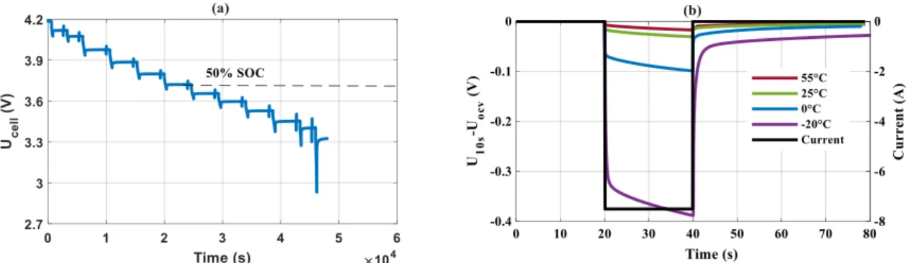
OCV is the potential difference between positive and negative electrodes when the electrochemical energy storage elements are stored. This voltage depends on the active materials in the electrochemical energy storage elements, it varies with the SOC, the temperature and the State Of Health (SOH) of the electrochemical energy storage elements [31]. OCV can be measured by two techniques: GITT or by applying a low charge/discharge current. GITT consists of a series of charge/discharge current pulse alternated by a break. As shown in Figure 1-8, this diagram illustrates the OCV measurement by GITT. The discharge/charge current pulse allows the LiBs to be placed at the different SOCs. Then the cell is put to rest in order to reach its thermodynamic equilibrium, the OCV is the value at the end of the relaxation phase, which represents by a cycle for discharge and by a cross for charge. The relaxation time depends on the discharge/charge current, the SOC and the discharge/charge temperature. Sauer et al. [31] showed that high current, low SOC and low temperature required a long relaxation time.
According to the literatures [33] [34] [35], the OCV obtained by a charge/discharge at low current (less than C/20) is considered as the pseudo-OCV. In theory, the state of charge can be determined from a simple reading of pseudo-OCV. However, the temperature slightly impacts the pseudo-OCV versus SOC curve [36]. Otherwise, an OCV value can significantly distort the SOC determination for LFP/graphite Li-ion cell (Figure 1-9), from 10% to 90% SOC, the pseudo-OCV value is always 3.25V [37].
Figure 1-9 Pseudo OCV-SOC curves based on discharge at different temperatures for a LFP/graphite cell [35]
Compared to these two techniques, the GITT allows measuring both OCV and internal resistance through a relaxation phase. However, the duration of relaxation to obtain an OCV after a pulse discharge at -20 °C and 0 °C was approximately six times higher than that for an OCV measured at 25 °C and 55 °C for a Li-ion cell (Figure 1-10). Therefore, the test lasts on average more than 50h by applying the GITT technique at low temperature. In addition, the relaxation time depends on the SOC. While, the low current discharging lasts less time in this case.
Figure 1-10 Relaxation time required at different temperatures and varied SOCs by technique of GITT for a NMC/LTO Li-ion cell [31]
Characteristic of LiBs, SCaps and LiCs with characterization methods
For SCaps, a significant self-discharge behaviour is observed after a relaxation phase. Voltage losses in the range of 5-60% occur over two weeks [38]. It is therefore not common to use the OCV parameter in the case of SCaps. The high potential and temperature promote the self-discharge. Furthermore, the self-discharge introduces a leakage current, which is the sum of the currents of all processes because of the parasite reactions and the replacement of electric charge through the SCaps. The self-discharge rate is higher in the SCaps compared to the LiBs [39].
1.3.2 Internal resistance or ESR
When the current flows through the cell, a voltage drop appears that is considered due to the internal resistance. The internal resistance is tens milliohms for the LiBs and over hundred microohms for the SCaps at the fresh state. The electrochemical energy storage element is considered at the first End Of Life (EOL) when its internal resistance doubles.
According to the IEC 62660-1 standard [28], the internal resistance of LiBs is characterized by the voltage repose to a current excitation profile. This profile consists of several 10s discharge/charge current pulse alternated by 10min rest time. Furthermore, the current amplitude varies and increases successively. This profile is applied at 3 SOCs (20%, 50%, 80%) and at 4 temperatures (40°C, 25°C, 0°C, -20°C). The profile for internal resistance measurement in this study is illustrated in Figure 1-11 (a), 20s of discharge/charge pulse currents with 40s rest are selected. Thereby, the internal resistance is calculated by equation (1.1), where 𝑈𝑥𝑠 is the voltage at the end of 20 second, 𝑈0𝑠 is the voltage before the pulse and 𝐼𝑑𝑐ℎ/𝑐ℎ is the discharge or charge pulse current.
𝑅𝑖𝑛𝑡 = |𝑈𝑥𝑠− 𝑈0𝑠
𝐼𝑑𝑐ℎ/𝑐ℎ | (1.1) 𝐸𝑆𝑅 = | ∆𝑈3 𝐼𝑑𝑐ℎ
| (1.2)
Figure 1-11 (a) Pulse current profile for Rint determination of LiBs (b) Voltage profile for ESR
determination of SCaps in IEC 62576 standard [30]
For SCaps, the internal resistance is represented by the Equivalent Series Resistance (ESR). In the IEC 62576 standard [30], ESR is characterized by the profile Figure 1-11 (b), the
curve through U1, U2 and the point at the beginning of discharge. 𝐼𝑑𝑐ℎ is the discharge current.
Another method for ESR characterization is often found in literatures. This method is based on a measurement of 5s potential difference ∆𝑈. The difference of potential is calculated before and after 5s when the charge/discharge current becomes zero.
1.3.3 Impedance
The internal resistance is the ration between a voltage drop and direct current (DC). However, if the applied voltage is oscillated by a sinusoidal wave, the current will be converted to alternative (AC). The proportionality between potential and current is a complex number, which is the impedance of electrochemical energy storage systems. Electrochemical Impedance Spectroscopy (EIS) is a technique that is used to characterize the impedance of different electrochemical energy storage systems. There are two modes of EIS. In potentiostatic mode, the excitation is performed by a low amplitude sinusoidal voltage (~10mV). While, in galvanostatic mode, the excitation is based on a low current (~100mA). EIS is a characterization technique based on the frequency domain, which signifies that the impedance measurement is performed at multiple frequencies. The wide frequency range covers from 10mHz to 10kHz allows to identify all the physical and chemical phenomena in electrochemical energy storage systems.
Figure 1-12 Impedance spectrum for NMC/graphite Li-ion cell at 30% SOC at 45°C in galvanostatic mode [10mHz-10kHz] with corresponding equivalent circuit model
A typical impedance spectrum for Li-ion cell is shown in Figure 1-12, where the physical-chemical phenomena of Li-ion cell can be characterized at the specific frequency. At high frequency range, R1 is due to the connection resistance and electrolyte. At mi-frequency
range, the charge transfer with SEI can be determined by the two half circles. At low frequency, the diffusion phenomenon is detected at low frequency range. In addition, this spectrum can be simulated by an equivalent circuit with various electrical components (Resistance (R), Constant Phase Element (CPE)) with a voltage source (OCV). The values of R and CPE under various conditions (T, SOC, ageing state) can be followed to evaluate the properties of different phenomena in Li-ion cells.
1.3.4 Capacity or capacitance
Capacity or capacitance is the amount of the electric charge delivered or stored by an electrochemical energy storage element. For LiBs, the available capacity (Q in Ah) is determined by the equation (1.3), it is calculated by the integral of the discharge current 𝐼𝑑𝑐ℎ
Characteristic of LiBs, SCaps and LiCs with characterization methods
over a given period dt between initial state ei and final state ef. In IEC 62660 [28], the initial
state is the maximum voltage, the final state is the minimum voltage defined by the manufacturer for discharge. For SCaps, according to IEC 62576 [30], the capacitance (C in F) is determined by equation (1.4), where U1 and U2 are 0.9Ur and 0.7Ur, respectively, as
illustrated in Figure 1-11 (b), E is the variation of energy between these two potentials. As internal resistance, the capacitance is another criterion to evaluate the performance of electrochemical energy storage elements. When the capacity reaches 80% of its initial value, the elements are considered as the first EOL.
Several parameters can impact the capacity/capacitance value, such as the discharge current, the temperature of test and the previous charge method. In the case of LiBs, the discharge current is defined by the discharge rate, it is expressed in combination of a number and a letter C. Concerning the example of a cell of capacity 10Ah, when the regime of discharge is C/2, this means that the Li-ion cell can provide the continuous discharged current of 5A during 2 hours. Furthermore, when the discharge rate is 10C, the cell delivers 100A during 6 minutes.
According to the IEC 62660 standard [28], C/3 is considered as a standard current for the lithium-ion cell that is dedicated to energy-type applications, while 1C for the power-type applications. 𝑄 = ∫ 𝐼𝑑𝑐ℎ𝑑𝑡 𝑒𝑓 𝑒𝑖 (1.3) 𝐶 = 2𝐸 𝑈2² − 𝑈1² (1.4) 1.3.5 State of charge
In LiBs, SOC is defined by the equation (1.5), it is the available capacity (𝑄𝑑𝑖𝑠𝑝) relatively to a reference capacity (𝑄𝑟𝑒𝑓), the reference capacity is often defined by users. For the SCaps, the SOC is calculated differently. It is expressed in the equation (1.6), where 𝑈𝑜𝑐 is
the voltage of SCaps after the relaxation and 𝑈𝑚𝑎𝑥 is the maximum voltage. SOC varies between 0% and 100%. This parameter is sensitive to the current, the temperature and the SOH of electrochemical energy storage elements.
𝑆𝑂𝐶𝐿𝑖𝐵 = 𝑄𝑑𝑖𝑠𝑝 𝑄𝑟𝑒𝑓 × 100% (1.5) 𝑆𝑂𝐶𝑆𝐶𝑎𝑝 = ( 𝑈𝑜𝑐 𝑈𝑚𝑎𝑥 )² × 100% (1.6)
1.3.6 Energy or power density
these equations is similar, but the energy of LiBs is stored between initial and final states, which correspond to the maximum voltage and the minimum voltage. Traditionally, the energy of SCap is stored between 0.5UR et UR, respectively, because the electric charge is nearly void
below 0.5UR for SCaps.
Equation (1.9) and equation (1.10) show the power density for LiBs and SCaps, respectively. The test, which makes it possible to determine the power density for the LiBs, is based on the current profile in IEC 62660 (Figure 1-11 (a)), where 𝑈10𝑠 is the voltage of 10s by applying a current pulse and 𝐼𝑑𝑐ℎ_𝑚𝑎𝑥 is the maximum current pulse. For SCaps, the power
density is dependent on ESR. The energy/power densities are all sensitive to the temperature, the current, the SOC as well as the SOH.
𝐸𝐿𝑖𝐵 = 1 𝑚∫ 𝐼𝑑𝑐ℎ𝑈(𝑡)𝑑𝑡 𝑒𝑓 𝑒𝑖 (1.7) 𝐸𝑆𝐶𝑎𝑝= 1 𝑚∫ 𝐼𝑑𝑐ℎ𝑈(𝑡)𝑑𝑡 𝑡0.5𝑈𝑟 𝑡𝑈𝑟 (1.8) 𝑃𝐿𝑖𝐵 = 𝑈10𝑠× 𝐼𝑑𝑐ℎ_𝑚𝑎𝑥 𝑚 (1.9) 𝑃𝑆𝐶𝑎𝑝= 0.25𝑈𝑟² 𝑚 × 𝐸𝑆𝑅 (1.10)
1.4 Electrochemical energy storage systems for aeronautical applications
Developing the more electrical aircraft is ongoing to meet the regulation of environment. In France, the objective on reduction of polluting emission by aircraft must be reached more than 20% until 2025. The only primary source of energy for a civil aircraft today is kerosene. Based on this kerosene, three sub-sources of energy are generated according to hydraulic, pneumatic and electric system. The More Electrical Aircraft (MEA) aims to replace the hydraulic and/or pneumatic systems by electrical systems [40].
Electrochemical energy storage elements are one of the indispensable components in the electrical system for an aircraft [41]. They are used to start the engines and Auxiliary Power Unit (APU), to maintain the AC/DC network, to guarantee energy and power for avionics equipment in case of emergency situation, to feed navigation units, flight controls and to provide electricity for ground maintenance [42] [43]. Most of these functions are critical. 1.4.1 Electrochemical energy storage systems used in aircraft
Historically, Vented Lead-Acid batteries (VLA) was installed in aircraft until the 1950s. Then, Vented Nickel-Cadmium batteries (VNC) were replaced. After that, Sealed Nickel Cadmium (SNC) and Sealed Lead Acid (SLA) batteries are widely developed and installed in military and commercial aircraft, such as the C-130 military aircraft, the F-16 fighter and Boeing 777[42] [43]. In the 2000s, LiBs began to be applied in aircraft thanks to their high energy and power density compared to SNC and SLA.
Figure 1-13 illustrates some examples of batteries used in aircraft. They are all housed in an aluminium container. These batteries serve as a secondary energy source in aircraft. In general, several cells are put in series in a battery to provide a voltage around 28V, which corresponds to the voltage level of 28V DC bus in aircraft. The number of cells placed in series depends on the technology.
Electrochemical energy storage systems used in aircraft
In Figure 1-13, the voltage of RG-145-2 lead acid battery manufactured by CONCORDE contains 12 cells in series. This battery has a capacity of 17Ah. The 2758 Ni-Cd battery from SAFT contains 20 cells in series, its capacity is 23Ah. It is installed in A318, A319, A320 and A321. The SAFT 450 VH1 lithium-ion battery has a capacity of 45Ah, it contains 7 cells in series, which is installed in A350 XWB.
Figure 1-13 Example of batteries used in aircrafts
Besides the batteries, SCaps can be also found in A380. They allow to open the aircraft safety doors in case of emergency. The operation of these heavy doors is controlled by a supercapacitor module, which is independent of the central power system in the aircraft [44]. 1.4.2 Energy and power requirements in more electrical aircraft
As illustrated in Table 1-4, the on-board electric power requirements for aircraft have increased particularly in last decade years. This increase is directly linked with the power requirements of additional avionics systems and passenger comfort [45].
The more electrical aircraft A380 already flies in 2005 (Table 1-4). It has 4 main generators of 150kVA to ensure the electrical power requirements. The innovate architect based on 2 hydraulic and 2 electrical systems replace the traditional 3 hydraulic and 2 electrical systems [46]. Another example of the MEA is the Boeing 787 (Table 1-4), which has 4 generators of 250kW without the pneumatic systems [46]. The evolution of a conventional aircraft towards the MEA is possible thanks to the new architect of electrical distribution system and progress on the reliability and robustness of the components used in electrical system.
Aircraft Concorde A300 A300 A340 A380 B787
Year 1969 1972 1992 1991 2005 2009
Power (kVA) 240 250 300 460 600 1000
of electrochemical energy storage. Electrochemical energy storage systems could be a one type of the promising candidate for the electrification of non-propulsive functions and electric propulsion [47] [48]. The current electric propulsion aircraft is yet limited to small aircraft. Airbus group has launched an « E-Fan » project in 2011. E-fan is a prototype of the aircraft with 100% electric propulsion. It has two electric motors powered by lithium-ion polymer batteries of 250V with 1h autonomy.
1.4.3 Issues of electrochemical energy storage elements for aeronautical usage
Current technologies of electrochemical energy storage have multiple limitations for aeronautical usage. Two major issues are discussed in detail below. The first one concerns the gap of the energy and power densities for electrochemical energy storage elements versus the electrical energy requirements in aircraft. The second one concerns the reliability and robustness of these electrochemical energy storage elements under the aeronautical conditions [43].
1.4.3.1 Gap between technologies of electrochemical energy storage and electrical energy requirements in aircraft
Despite the significant improvements are made to the latest generation electrochemical energy storage technologies, their energy and power density are still lower than the on-board electrical requirements in aircraft. For instance, a long line aircraft cruise for two hours requires about 100kWh of electrical energy. To accomplish this mission, the aircraft must carry a mass of battery 60 times larger than its kerosene equivalent [49].
Increasing the energy density in the complete system is a crucial challenge for the electrification of aircraft. Aeronautical manufacturers estimate that the minimum energy density required for a more electrical airliner is 500Wh/kg [4]. The energy density for the different technologies of batteries is shown in Figure 1-14, among the current technologies, LiBs have a higher energy density that is in the range of 200Wh/kg.
To achieve the goal of 500Wh/kg, new technologies are being developed. Future LiBs and lithium-sulfur batteries based on new electrode materials allow to increase energy density. The concept of zinc-air and lithium-air is similar. This type of battery has a negative metal electrode (zinc or lithium) and a positive porous carbon electrode, both are immersed in the electrolyte. It can offer a high energy density, since the active material of oxygen does not need to be stored in the electrode, it is access in the air. Therefore, the energy density can be enhanced 5 times than LiBs theoretically.
Electrochemical energy storage systems used in aircraft
Figure 1-14 Battery technologies overview regarding energy densities (current, expected) and price
[50]
Despite the eventual electrochemical energy storage technologies could not provide the energy requirements in aircraft. However, the multiple storage technologies such as the LiBs, the SCaps and the fuel cell are able to meet the different electrical energy needs in aircraft, especially for the non-propulsive functions. As illustrated in Figure 1-15 the diagram represents the variety electrical energy needs in the MEA. It can be observed that each application has a specific energy and power needs. Overall, the technology ensures the most of aeronautical applications if it can be operated between 1C to 20C. Therefore the electrochemical energy storage elements can be envisaged for aeronautical usage.
Figure 1-15 On-board multiple electrical energy requirements in aircraft [51]
1.4.3.2 Issues related to aeronautical conditions
The LiBs and SCaps for aeronautical usage under specific conditions is critical, especially, the safety concerns the operation and the performance in extreme conditions.
• The safety issues of electrochemical energy storage elements
The safety during operation is the first criterion to be considered before integrating an electrochemical energy storage element in aircraft. In 2011, Boeing 787-8 Dreamliner was the first airliner using the LiBs. Two identical rechargeable Li-ion batteries are installed in Boeing 787. Each battery has a capacity of 75Ah, which contains eight cells, ranging from 2.5V to 4.2V [52]. Lithium Cobalt Dioxide (LiCoO2) technology had been chosen as the positive electrode material for these cells. However, the LiBs were rejected after a few incidents between January and May of 2013 [53]. In January 2013, a Li-ion battery in Boeing 787 overheated and caught fire. According to the National Transportation Safety Board (NTSB), the thermal runaway of this battery was probably due to the internal short circuit. In the same year, Airbus therefore abandoned the use of LiBs in the A350. Afterwards, Boeing has made some improvements on the battery case to avoid the thermal runaway propagation. However, a flight was cancelled following the discovery of smoke from a lithium-ion battery during pre-boarding control [53].
The smoke, fire or even explosion caused by thermal runaway are the unacceptable issues in aircraft. Thermal runaway occurs when the cell is under abuse conditions [54]. For example, the mechanical abuse can trigger a short circuit in the cell, which introduces a large amount of heat. The cell is therefore overheated then its temperature exceeded certain threshold and thermal runaway is occurred.
The risks of thermal runaway is difficult to predict because it is an steeply phenomenon that could be occurred during the battery dysfunction [55]. In order to reduce these risks, in addition to the use of more stable and safe materials for electrochemical energy storage elements, enhance the mechanical proprieties of packaging is necessary. This allows to avoid the mechanical abuse. Using the electronic devices can prevent external short circuit, overcharging or over-discharging. For example, the Positive Thermal Coefficient (PTC) switches the current off when the cell is overheated. The Battery Management System (BMS) is used to monitor the battery SOH by warning users when there is a potential hazard [54].
• Performance of electrochemical energy storage elements under extreme
conditions
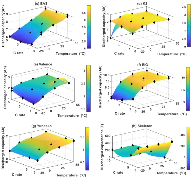
The LiBs and SCaps are installed in the electronic equipment bay or in the cabin of the aircraft, these zones are under pressure [56]. But in the system failure situation, the LiBs and SCaps must be able to provide power to the avionic equipment at low temperature and low pressure. Regarding the temperature, as shown in Figure 1-16, the available capacity decreases with temperature for the different technologies of LiBs, which limits the energy; the resistance increases as the temperature drops, which limits the power.
Regarding the high amplitude, Jeevarajan [57] performed electrical tests under low pressure, it observed that the capacity of a pouch lithium cell loses 35% relatively to its initial
Electrochemical energy storage systems used in aircraft
capacity after 6 hours at 0.6Bar. Therefore, mastering the characteristics of electrochemical energy storage elements extreme conditions are predominant for aeronautical usage.
Figure 1-16 Discharged capacity and resistance of Li-ion cells at different temperatures (-20°C, 0°C, 25°C et 55°C) [58]
1.4.4 Standards and certifications
The challenges of embedding the electrochemical storage elements in MEA are not only at the level of technology and the aeronautical conditions, but also a complex issue on the definition of regulations, standards and certifications. In general, aeronautical standards are always developed by the experts in the aviation committee, such as the International Civil Aviation Organization (ICAO), the European Aviation Safety Agency (EASA) in Europe and the Federal Aviation Administration (FAA) in the USA, etc.
Specific standards concerning the usage of batteries for civil aircraft equipment are several, such as the RTCA standards DO-293, DO-311, DO-188 and DO-160 [59]. The standard of DO-293 addresses the nickel-cadmium, nickel-metal-hydride and lead-acid batteries on the choice of technologies, sizing, packaging, ventilation and the conditions for the storage and operation of these batteries. The DO-311 is applied to rechargeable LiBs installed permanently in the aircraft. It offers the characterization protocols of the performance of LiBs. In addition, the standard criteria are constructed to verify the reliability and to ensure the safety operation of LiBs. Respecting these standard requirements ensures the safety of battery systems under aeronautical conditions. The standard of DO-188 focuses on Emergency Locator Transmitter (ELT) battery regulations. Furthermore, the environmental conditions of tests, including the investigation and the maintenance after incidents of the battery systems are defined in the standard DO-160.
1.5 Conclusion
In this chapter, the chemical compositions, the working principles and the different forms of LiBs, SCaps and LiCs are presented in detail and compared between themselves. The materials used in these elements and the way of storing the electric charges determine their application roles (energy or power type) in a system.
parameters are in common for LiBs, SCaps and LiCs. These interdependent parameters allow to quantify the performance of the electrochemical storage elements.
Finally, the development of electrochemical energy storage technologies used on board the aircraft is presented. The electrochemical storage element seems to be a promising candidate to integrate in the MEA. But above all, issues related to safety and performance under aeronautical conditions need to be addressed. The specific aeronautical standards related to the implantation of LiBs exist to ensure the least risks.
Chapter 2
Comparative performance quantification of
electrochemical energy storage elements by
experiments and modelling
Table of contents
2.1 Introduction ... 32 2.2 Experiments ... 32 2.2.1. Tested technologies of LiBs, SCaps, LiCs and Li-S ... 32 2.2.2. The CaCySSEE platform ... 35 2.3 Reference test design ... 36 2.3.1. Reception tests ... 36 2.3.2. Initial tests ... 36 2.3.3. Performance tests ... 37 2.3.3.1 Incremental discharge ... 37 2.3.3.2 Available discharged capacity ... 38 2.3.3.3 Maximal power discharge ... 38 2.3.4. Ageing tests ... 39 2.3.5. Abuse tests ... 39 2.3.6. Available discharged capacity for LiBs, LiCs and SCaps ... 39 2.4 Cell to cell characterization ... 41 2.5 Non-isothermal Ragone plots of 18650 Li-ion cells from datasheet and galvanostatic discharge tests ... 41
2.5.1. Performance quantification with experimental approach ... 42 2.5.2. Comparison for constant current discharge ... 43
2.5.3.2 Thermal model ... 50 2.5.4. Validation of Ragone Plot model ... 53
2.5.4.1 Ragone plot model for 25°C ... 54 2.5.5. Extending Ragone plot model for wide operating temperature range ... 56 2.5.6. Enhanced non-isothermal Ragone plot ... 58 2.6 Conclusion ... 59
2.1 Introduction
In this chapter, we focus on the comparative study of performance quantification for all investigated ElectroChemical Energy Storage (ECES) elements. Two main sections are included in this chapter.
The first section is dedicated to introduce the characteristic of investigated LiBs, SCaps, LiCs and the experimental equipment. Then, a large experimental matrix is built by considering all the technical datasheet and aeronautical conditions. A series of specific protocols are considered as the reference tests to quantify the performance of different electrochemical energy storage elements, especially, in terms of energy density and power density. Furthermore, the experimental tests cover a wide temperature range from -20°C to 55°C and it was designed for the energy-type, the power-type and the high power-type of applications.
In the second section, the study focuses on establishing a Ragone plot for generic chemistry (NMC/graphite+SiO, NCA/graphite) of Li-ion cells. The proposed method is based on a simple and efficient coupled electrical-thermal model. This model is parametrized by the experimental data from the investigated reference tests. In addition, the proposed Ragone plot model can be extended to a wide operating temperature range [-20°C, 55°C] under multiple power levels and it has a good accuracy. A non-isothermal Ragone plot is established for the first time, which could be employed as a conception aid tool for the selection of Li-ion cells in system design process.
Finally, the energy density and the power density at the fresh state in a wide temperature range [-20°C, 55°C] can be quantified according to experiments and modelling.
2.2 Experiments
2.2.1 Tested technologies of LiBs, SCaps, LiCs and Li-S
In this study, nine technologies of commercials LiBs, SCaps, LiCs and Li-S are investigated. Among them, 6 LiBs technologies, 1 SCap technology, 1 LiC technology and 1 Li-S technoly. They are considered as the promising candidates for aeronautical usage according to industrial partners. All the main characteristics such as manufacturer, form, chemistry (CHEM), capacity or capacitance (C), energy density (E), power density (P), minimal and maximal voltage (Umin-Umax), nominal voltage (Un), internal resistance or ESR
(Rint/ESR), recommended maximal current of charge and discharge (Ich/Idch) and temperature
![Figure 0-2 Li-ion battery of Boeing 787 Dreamliner airline before and after accident [5]](https://thumb-eu.123doks.com/thumbv2/123doknet/14529259.723320/13.892.180.711.234.502/figure-li-ion-battery-boeing-dreamliner-airline-accident.webp)

![Figure 1-10 Relaxation time required at different temperatures and varied SOCs by technique of GITT for a NMC/LTO Li-ion cell [31]](https://thumb-eu.123doks.com/thumbv2/123doknet/14529259.723320/27.892.250.613.813.1094/figure-relaxation-required-different-temperatures-varied-socs-technique.webp)
![Figure 1-12 Impedance spectrum for NMC/graphite Li-ion cell at 30% SOC at 45°C in galvanostatic mode [10mHz-10kHz] with corresponding equivalent circuit model](https://thumb-eu.123doks.com/thumbv2/123doknet/14529259.723320/29.892.140.747.549.752/figure-impedance-spectrum-graphite-galvanostatic-corresponding-equivalent-circuit.webp)


![Figure 3-2 SEM images of the graphite electrodes disassembled from the Graphite/LFP full cells (a)Reference; (b)power cycling at 25°C; (c)power cycling at 0 °C; (d) power cycling at -18°C [110]](https://thumb-eu.123doks.com/thumbv2/123doknet/14529259.723320/71.892.229.642.581.895/figure-graphite-electrodes-disassembled-graphite-reference-cycling-cycling.webp)
