Biodegradable Microfluidic Scaffolds for Vascular Tissue Engineering
byChristopher John Bettinger S.B. Chemical Engineering
Massachusetts Institute of Technology, 2003
SUBMITTED TO THE DEPARTMENT OF BIOLOGICAL ENGINEERING IN PARTIAL FULFILLMENT OF THE REQUIREMENTS FOR THE DEGREE OF
MASTER OF ENGINEERING IN BIOLOGICAL ENGINEERING AT THE
MASSACHUSETTS INSTITUTE OF TECHNOLOGY JUNE 2004
Copyright © 2004 ChristopherJohn Bettinger. All rights reserved.
The author hereby grants to MIT permission to reproduce and to distribute publicly paper and electronic copies of this thesis document in whole or in part.
Signature of
Author -...
Department of Biological Engineering
C ertified by ... ... ... L ... - - - -_ ..._._._._._._._..._._._._ Prof. Robert Langer Professor of Chemical and Biological Engineering Thesis Advisor Accepted by...
Prof. Douglas A. Lauffenburger Professor of Chemical and Biological Engineering Chairman, Graduate Program in Biological Engineering
MASSACHUSE-TTS INSTITUTE OF TECHNOLOGY
Biodegradable Microfluidic Scaffolds for Vascular Tissue Engineering
byChristopher John Bettinger
SUBMITTED TO THE DEPARTMENT OF BIOLOGICAL ENGINEERING IN PARTIAL FULFILLMENT OF THE REQUIREMENTS FOR THE DEGREE OF
MASTER OF ENGINEERING IN BIOLOGICAL ENGINEERING
Abstract
This work describes the integration of novel microfabrication techniques for vascular tissue engineering applications in the context of a novel biodegradable elastomer. The field of tissue engineering and organ regeneration has been born out of the high demand for organ transplants. However, one of the critical limitations in regeneration of vital organs is the lack of an intrinsic blood supply. This work expands on the development of microfluidic scaffolds for vascular tissue engineering applications by employing microfabrication techniques. Unlike previous efforts, this work focuses on fabricating this scaffolds from poly(glycerol-sebacate) (PGS), a novel biodegradable elastomer with superior mechanical properties. The transport properties of oxygen and carbon dioxide in PGS were measured through a series of time-lag diffusion experiments. The results of these measurements were used to calculate a characteristic length scale for oxygen diffusion limits in PGS scaffolds. Microfluidic scaffolds were then produced using fabrication techniques specific for PGS. Initial efforts have resulted in solid PGS-based scaffolds with biomimetic fluid flow and capillary channels on the order of 10 microns in width. These scaffolds have also been seeded with endothelial cells and perfused continuously in culture for up to 14 days resulting in partially confluent channels. More complex fabrication techniques were also
demonstrated. A novel electrodeposition technique was used in the fabrication of biomimetic :tnicrofluidic masters. Thin-walled devices were also synthesized to accommodate the relatively low gas permeability of PGS.
Thesis Advisor: Professor Robert Langer
Acknowledgements
June 2004This thesis was funded by the Charles Stark Draper Laboratory IR&D Project No. 2007. First and foremost, I would like to thank my family for their motivation and continued support in pursuing my personal goals. This thesis would not have been possible without the love and encouragement of Teresa Tao who has always been my guiding light. I would also like to thank Chris, Buddy, Roger, Aaron and Dickey for their continued creative inspirations during the development of my thesis work. I would like to thank the Departments of Chemical Engineering and Biological Engineering at MIT for providing extraordinary educational opportunities in the classroom as well as in the laboratory, leaving me well prepared to pursue a career in bioengineering research. Specifically, I am grateful for the opportunity to work in the Langer Lab and have Prof. Robert Langer as my thesis supervisor. His creativity, vision, and dedication to science and engineering have been truly inspirational. Special thanks to Jeff Borenstein, Brian Orrick, and the entire Draper
Laboratory for their financial support and use of shared facilities.
On a more personal level, I would like to thank the brotherhood of Alpha Mu Chapter of Phi Kappa Sigma whose values and beliefs have equaled the stars in endurance and have helped sculpt me into the man I am today. My membership in this fraternity was
instrumental in my undergraduate education as I learned both the power of the beacon of knowledge and the strength of the human spirit. I shall forever carry with me the lessons and love of life that I have gained by living with these fine gentlemen.
TABLE OF CONTENTS
CHAPTER 1:: AN INTRODUCTION TO TISSUE ENGINEERING AND ORGAN
REGENERATION... 9
1.1 THE DEMAND FOR ENGINEERED TISSUES ... 9
1.2 BIOLOGY AND BIOCHEMISTRY OF BLOOD VESSELS ... I 1
1.2.1 Relevant Biomolecular Signaling and Pathways in Blood Vessel Proliferation and
Maturation...
1 1
1.2.2 Role of Microenvrionment in Blood Vessel Maturation ... 15
1.3 VASCULAR TISSUE ENGINEERING ... ... 20
1.3.1 [)elivery of Tissue Growth Factors ...
20
1.3.2 Cell-Matrix Interactions for Vascular Tissue Engineering ... 24
1.4 APPLICATIONS OF MICROFLUIDIC DEVICES FOR TISSUE ENGINEERING ... 25
1.5 BIOMATERIALS ... 28
1.5.1 Role of Biomaterials in Tissue Engineering ...
28
1.5.2 Existing Biodegradable Elastomers ... 30
1.6 POLY(GLYCEROL-SEBACATE) ... 31
1.6.1 Shortcomings of Existing Bio-Elastomers ... 3 1
1.6.2 Poly(glycerol-sebacate) -- "Biorubber" ... . ... .. 31CHAPTER 2: MEASURING TRANSPORT PROPERTIES OF
POLY(GLYCEROL-SEBACATE) ...
...
34
2.1 INTRODUCTION ... 34
2.1.1 Rubbery vs. Glassy Polymers ...
...
34
2.1.2 Theory ...
35
2.1.3 Measurement of Gas Permeabilities ...
37
2.2 EXPERIME NTAL METHODS ... 39
2.2.1 Time-lag Diffusion Experimental Apparatus ... 39
2.2.2 Preparation of PGS Membranes ...
41
2.2.3 Time-lag Diffusion Experimental Procedure ... 43
2.3 RESULTS ... 43
2.4 DISCUSSION ... 45
2.4.1 Explanation of Trends in Transport Coefficients ... 45
2.4.2 Effect of Cross-linking on Measured Transport Coefficients ...
46
2.4.3 Relative Permeability of PGS ...
...
47
2.4.4 Design Applications and Summary ...
48
CHAPTER 3: FABRICATION AND ENDOTHELIALIZATION OF SIMPLE PGS
MICROFLUIDIC SCAFFOLDS ...
52
3.1 INTRODUCTION ... 52
3.1.1 PGS-based Tissue Engineering Scaffolds ... 52
3.2 MATERIAILS AND METHODS ... ... 54
3.2.1 Microfabrication of Bulk Silicon Microfluidic Masters ... 54
3.2.2 Fabrication of PGS-based Microfluidic Scaffolds ...
56
3.3 RESULTS ... 57
3.3.1 Characterization of PGS Microfluidic Scaffolds ...
57
3.3.2 Vascuarlized PGS Microfluidic Scaffolds ... 60
3.4 D ISCUSSION ...
61
3.4.1 Flow Rates and Fluid Mechanics in PGS Microfluidic Scaffolds ... 64
3.4.2 Summary and Future Direction ... 66
CHAPTER 4:: FABRICATION OF COMPLEX PGS MICROFLUIDIC SCAFFOLDS .. 68
4.1 INTRODUCTION ... 68
4. 1.1 Channel Height Constraints in Bulk-Etched Silicon Masters ... 68
4.1.2 Microfabrication Using Novel Three-Dimensional Electroplating Technique ... 69
4.1.3 Ultra-thin Layers of PGS ... 73
4.2 MATERIALS AND METHODS ... 74
4.2.1 Microfabrication of Gold Patterned Substrates ... 74
4.2.2 Ellectrodeposition of Nickel ...
75
4.2.3 Feature M etrology ... 76
4.2.4 Micromolding of Poly(glycerol-sebacate) ...
76
4.2.5 Synthesis of Ultra-thin Layers of PGS ... 77
4.3 RESULTS ... 78
4.3.1 Multi-level Electrodeposited Nickel Microfluidic Masters ... 78
4.3.2 Ultra-thin Layers of PGS and Thin Walled PGS Scaffolds ... 81
4.4 DISCUSSION ... 82
4.4.1 Improved Channel Geometry ... 83
4.4.2 Comparison to Existing Method
.
... 85
s
4.4.3 Thin-Walled PGS Microfluidic Devices ... 86
4.4.4 Summary and Future Work ... 86
CONCLUSIONS ...
88
LIST OF FIGURES
FIGURE 1. OVERVIEW OF REGULATION OF VESSEL ASSEMBLY ... 12
FIGURE 2. RESPONSE OF ECS TO VARIOUS SHEAR STRESS PATTERNS ... 16
FIGURE 3. SIMULATED VELOCITY VECTOR FIELDS IN MICROFLUIDIC DEVICES ... 19
FIGURE 4. HETEROGENOUS POLYMER CONTROLLED DRUG RELEASE SYSTEM ... 22
FIGURE 5. PERFUSION CULTURE OF ECS IN SILICON MICROMACHINED NETWORKS2 8 ... 27
FIGURE 6. STRESS STRAIN CURVE OF PGS COMPARED TO OTHER MATERIALS ... 32
FIGURE 7. IN VITRO COMPARISON OF 3T3 FIBROBLASTS ON PGS (A) AND PLGA (B) ... 33
FIGURE 8. THREE STAGES OF GAS PERMEATION ... 37
FIGURE 9. TIME LAG DIFFUSION EXPERIMENT ... 39
FIGURE 10. SCHEMATIC OF PERMEABILITY EXPERIMENTAL APPARATUS ... 41
FIGURE 11. PGS SYNTHESIS ... 42
FIGURE 12. PERMEABILITY SOLUBILITY AND DIFFUSIVITY OF SELECT GASES ACROSS PGS ... 44
FIGURE 13. RELATIVE PERMEABILITY OF OXYGEN AND CARBON DIOXIDE IN PGS ... 48
FIGURE 14. DIFFUSION-REACTION MODEL FOR PGS MEMBRANES ... 50
FIGURE 15. PROCESS FLOW FOR FABRICATING PGS MICROFLUIDIC SCAFFOLDS ... 54
FIGURE 16. PHOTOLITHOGRAPHY MASK FOR MICROFLUIDIC MASTER ... 55
FIGURE 17. A COMPLETED PGS-BASED MICROFLUIDIC SCAFFOLD . ... 58
FIGURE 18. CFD RESULTS OF MICROFLUIDIC NETWORK ... 59
FIGURE 19. CHARACTERIZATION OF PGS MICROCHANNELS ... 59
FIGURE 20. ENDOTHELIALIZATION OF HUVECS IN PGS MICROFLUIDIC SCAFFOLDS ... 60
FIGURE 21. SPATIAL CONSTRICTION OF EXPANSION OF CELLS IN MICROCHANNELS ... 64
FIGURE 22. CROSS-SECTIONAL SCHEMATIC OF FABRICATION OF A MULTI-LAYERED PGS MICROFLUIDIC SCAFFOLD ... 67
FIGURE 23. THREE-DIMENSIONAL ELECTRODEPOSITION OF NICKEL ... 72
FIGURE 24. FABRICATION OF MICROFLUIDIC MASTER FOR VASCULAR TISSUE ENGINEERING APPLICATIONS ... 73
FIGURE 25. INDIVIDUAL LAYOUTS FOR MICROFABRICATION OF ELECTRODEPOSITED SUBSTRATES ... .75
FIGURE 26. FABRICATION OF THIN-WALLED PGS MICROFLUIDIC TISSUE ENGINEERING SCAFFOLDS ... 78
FIGURE 29. THICKNESSES OF SPINCOATED PGS MEMBRANES ... 81 FIGURE 30. SEM CROSS-SECTION OF A THIN-WALLED PGS MICROCHANNEL ... 82 FIGURE 3 1. IMPROVED ASPECT RATIO OF MICROCHANNELS IN ELECTRODEPOSITED NICKEL M A STERS ... 84
LIST OF TABLES
TABLE 1. 2003 ORGAN RECIPIENT WAITING LIST BREAKDOWN BY ORGAN ... 9 TABLE 2. PERMEABILITY, DIFFUSIVITY, AND SOLUBILITY COEFFICIENTS OF OXYGEN AND
CARBON DIOXIDE IN POLY(GLYCEROL-SEBACATE) AT
STP
...44
TABLE 3. SUMMARY OF TRANSPORT COEFFICIENTS OF PGS RELATIVE TO OTHER MATERIALS... 47
TABLE 4. SUMMARY OF GAP DISTANCES BETWEEN CONDUCTIVE ISLANDS IN LAYOUTS ... 75
TABLE 5. FEATURE DIMENSIONS OF LAYOUT
A
ELECTROPLATED FOR48
HRS ...79
Chapter 1: An Introduction to Tissue Engineering and
Organ Regeneration
1.1 The Demand for Engineered Tissues
Tissue loss and organ failure are problems that have plagued health care throughout the world and in the United States. The financial burden of treating these patients have totaled more than $400BB USD annually":'. Standard treatments for organ loss include transplantation, surgical reconstruction, and the incorporation of artificial organs and systems. Although these techniques can save lives, they each carry significant drawbacks, which can negatively affect the patients' quality of life.
Reconstruction of lost or damaged tissue can often leave a patient with long-term problems. For example, colon cancer becomes prevalent in patients that undergo a treatment to redirect urine from the bladder to the colon3. Transplantation is limited by the amount of organ donors coupled with a rapidly increasing waiting list for organ recipients. In 2003, more than 80,000 patients on the organ recipient waiting list4 (Table 1).
Table 1. 2003 Organ Recipient Waiting List Breakdown by Organ. Organ Patients on Waiting List
Kidney 54,651 Liver 17,139 Pancreas 1,422 Kidney-Pancreas 2,420 Intestine 177 Heart 3,742 Heart-Lung 199 Lung 3,873
The problems with current treatments of organ failure and tissue loss have prompted the creation of the tissue engineering. The field of tissue engineering, referred today as regenerative medicine, is an interdisciplinary effort that combines the disciplines of medicine, engineering, and science in
growing, repairing, and improving tissue structure and function. There are three basic strategies that have been studied to create new tissues.
1. Isolated cells and cell substitutes. This treatment allows for an infusion of specific cells
into the patient without the complications of surgery. Although the cells may be manipulated prior to injection, the possibility of loss of cell function and immunological response are imminent.
2. Tissue growth factors. High, localized concentrations of signaling molecules could lead to organ regeneration. Success with this approach hinges not only upon the ability to produce massive quantities of these biomolecules, but also targeted delivery. Another strategy to utilize tissue growth factors for tissue engineering is the use of gene delivery systems to upregulate the local production of these growth factors.
3. Cell-matrix interactions with scaffolds. Matrices constructed out of natural or synthetic
materials can induce cell migration, act as immunoisolation barriers, and provide structural support for the cells to grow and proliferate. The ultimate goal is for the cells to grow and eventual replace a biodegradable scaffold. thereby forming tissue that is functionally equivalent to the desired tissue.
These strategies have been pursued in attempts to grow a variety of tissues including nerve, skin, cardiac and bone. More recent efforts have focused on developing strategies to engineer more complex organs such as the pancreas, kidney, and liver. The field of vascular tissue engineering has been born out of the demand for blood vessels of various dimensions for treatment of coronary artery and peripheral vascular diseases, the leading causes of mortality in the United States6. A more recent demand for vascular tissue engineering approaches has also matured to support parallel advances in tissue engineering. General tissue engineering strategies have relied on the natural in-growth of local blood vessels within tissue engineering devices to achieve permanent vascularization
after the device has been implanted. Although this technique may be sufficient for simple tissues such as skin, bone, or cartilage, it is not sufficient for highly vascularized organs such as the kidney and liver. Traditional tissue engineering approaches to these problems have focused on the in vitro growth of various combinations of endothelial cells and smooth muscle cells in macroscopic constructs using biomaterials such as Dacron7. Although these strategies have shown promise, they lack the ability to precisely control the cellular microenvironment. In vivo vascular tissue engineering therapies have attempted to induce blood vessel growth and maturation by using a variety of approaches including controlled drug release and gene therapy. Controlling the signaling molecules in the microemnvironment is essential for engineering native-like blood vessels in both in vivo and in
vitro approaches.
1.2 Biology and Biochemistry of Blood Vessels
It is tempting to overlook the importance of biochemical signaling pathways and concentrate on biomaterials and other design components when developing tissue-engineering platforms. However, it is of utmost importance to understand the relevant biochemical and signaling pathways that are present in the growth of tissues. More specifically, the proliferation and maturation of blood vessels is a critical component in vascular tissue engineering.
1.2.1 Relevant Biomolecular Signaling and Pathways in Blood Vessel
Proliferation and Maturation
The utilization of tissue growth factors is a promising approach for tissue engineering blood vessels. However, recent studies have determined that the growth and maturation of blood vessels is a complex biological process that involves numerous cell types and uses numerous signaling pathways (Figure 1). Spatio-temporal coordination between the cells and corresponding arrays of various
signals is critical for angiogenesis. Therefore, it is important to understand the details of the relevant biological signaling involved in angiogenesis and maturation first before the development of
potential therapies for vascular tissue engineering using tissue growth factors. In in vivo systems, endothelial cells (ECs) migrate and proliferate in the presence of large amounts of vascular endothelial growth factor (VEGF) to form new blood vessels in the presence of arteriogenetic environments, which will be discussed later8. These nascent blood vessels consist of a monolayer of ECs in a tubular conformation with individual cobblestone cell morphology. The first step towards maturation is the recruitment of surrounding mural cells. This process is regulated by four
processes; 1) platelet-derived endothelial growth factor (PDGF); 2) sphinogosine-1-phosphate-1 (S1P1)-endothelial differentiation sphingolipid G-protein-coupled receptor-1 (EDG1); 3) A tyrosine kinase receptor (Tie-2) and angiopoitein (Ang-1); 4) transforming growth factor (TGF-B).
zalion
Figure 1. Overview of Regulation of Vessel Assembly. After ECs self-assemble into
monolayer tubules, they begin recruiting pericytes using PDGF-B. This leads to maturation of the nascent blood vessels. The additional presence of Angl leads to further stabilization while Ang2 in combination with VEGF induces sprouting.
PDGF. PDGF is a molecule that is secreted by many cell types including ECs. However, the
importance of PDGF during blood vessel maturation has been supported through evidence of Pdg/b knockout mice, which encounter embryonic lethality9. These mice exhibit aberrant vessel
remodeling along with the absence of pericytes of the microvasculature"'. This observation illustrates the critical role that PDGF plays in recruiting local pericytes and eventual blood vessel maturation. Phenotypical similarities between PdgJb and Edgl knockout mice also suggest a similar importance of the EDG1 receptor during vessel development.
Tiel/2 Ligands and Angl/2 Receptors. The role of Tiel and Tie2 and their receptors, Angl and
Ang2 are also essential for maturation. Angl serves to stabilize nascent blood vessels, although the mechanism is still unclear. Alternatively, the effect of Ang2 appears to be situational. Namely, if local concentrations of VEGF are increased, Ang2 appears to induce arteriogenesis. However, if levels of VEGF are relatively low, then Ang2 serves to destabilize blood vessels". This hypothesis was tested in 3-D spheroidal co-culture assay. Direct contact between ECs and Angl-expressing mesenchymal cells leads to a decreased responsiveness to VEGF whereas the presence of Ang2 and VEGF results in angiogenesis. Further evidence of this effect has been shown in the
microvascularization of rat testes'2. Local injection of Ang2 in the testis increases endothelial cell proliferation as well as the volume of the interstitial space thereby supporting the proposed hypothesis.
TGF Pathways. Once the EC wall successfully recruits the pericytes, the ECs begin producing
TGF-B, which has been observed to interact with a number of signaling pathways between cells. In the context of blood vessel maturation processes, TGF-B1 promotes maturation by stimulating
extra-cellular matrix (ECM) production by differentiating mesenchymal cells to mural cells. TGF-B also acts on two complementary downstream pathways named TGF-B-ALK1 and TGF-B-ALK5 respectively. The ALK1 pathway serves to induce proliferation and migration of fibroblasts to the EC tube via the Idl protein. The ALK5 pathway induces the plasminogen activator inhibitor (PAI)1 in ECs, which promotes vessel maturation. Therefore, the relative strength of signaling present in the ALK1 and ALK5 pathways leads to cell migration and proliferation or vessel maturation.
Remodeling of Mature Vessels. The basement membrane and surrounding ECM provide
additional cues for the fate of blood vessels. Proteins that compose the ECM surrounding mature blood vessels fi.nction as storage sites for signaling molecules that regulate the proliferation, survival, and migration of the vessels. The degradation of this ECM by various proteases releases angiogenic molecules such as VEGF and fibroblast growth factor (FGF). Additionally, these
proteases also serve to release anti-angiogenic molecules by cleaving various ECM molecules or even the proteins themselves. For example, numerous approaches indicate that fibronectin, collagen, and their respective receptors are proangiogenic. Consequently, these space and time-dependent
concentration profiles of the various signaling molecules regulate the overall balance of proliferation and regression of ECs and mural cells alike. However, further elucidation of the complex,
multifactorial cell-matrix interactions must be attained before this information can be effectively applied in tissue engineering applications.
The Effect of Surrounding Tissues on Mature Blood Vessels. The thought that
microvasculature is a system of dormant, inactive tissues has been abolished. Instead, it is now thought that blood vessels, including ECs, are able to communicate with surrounding tissues, which
in turn affect their phenotypic disposition. In other words, blood vessels take on the attributes of their surrounding microenvironment while also maintaining some degree of variability in their eventual cell fate3. The surrounding tissues regulate the vessel architecture by means of VEGF. Locally secreted VEGF signals induce various types of EC behavior. In addition to the ubiquitous VEGF-A system, there has also been a recent discovery of tissue-specific vascular endothelial growth factors. For example, endocrine gland VEGF (EG-VEGF) is functionally similar, yet structurally distinct from its VEGF-A counterpart. Furthermore, EG-VEGF does not affect ECs from the aorta or umbilical vein, which leads to the hypothesis that such a molecule only functions in a specific organ. Therefore, tissue-specific VEGF may complement the more ubiquitous VEGF-A molecules in regulating EC growth and maturation in blood vessels.
1.2.2 Role of Microenvrionment in Blood Vessel Maturation
The previous section outlined the relevant biological pathways that are critical to the fate of blood vessels. Another critical element of blood vessel engineering is the precise control of the
microenvironment of the cells. In addition to the chemical environment, blood vessel maturation pathways are both directly and indirectly affected through physical parameters such as oxygen concentration, pH, hydrostatic pressure and mechanical shear stress. Carefully adjusting these parameters to create an angiogenic microenvironment could help advance tissue engineering of mature blood vessels in both in vivo and in vitro environments.
Mechanical Microenvironment - Shear Stress. Two types of shear stresses that ECs of blood
vessels are commonly exposed to are laminar (LSS) and distributed (DSS). LSS, which is associated with flow parallel to cell layers, can be further classified as either acute or chronic (Figure 2). LSS has also been shown to induce a variety of endothelial activation genes, which leads to a general
predisposition to arteriogenesis while DSS tends to suppress endothelial activation genes, which results in quiescence combined with a general anti-apoptotic and anti-inflammatory state. There have been various in vivo studies which suggest that arteriogenesis can occur when the mechanical environment both inside and outside the cell is changing'4. Subsequent studies have supported this model by suggesting that increases in shear rate function as the primary signal for arteriogenesis'5 Periodic shear stress has also been shown to both stimulate endothelial cell migration in non-confluent structures as well as assist in mechanisms of blood vessel maintenance. DSS, which is generally characterized as perpendicular flow relative to a cell monolayer, results in a number of cell activities, which eventually lead to atherogenesis in both acute and chronic timescales.
Laminar shear stress Disturbed shear stress
Acute (changes) Chronic Acute and Chronic
I. SNpprcmIon of cndoUlhelI Aclivaion gee" 2. Endotiheldi qudica , ami-apopltoik mnfl-ilawmmtoeryathereack Ig.,. , n/w---r rd I. Indntion of Enohelill activation gee. 2. Endothelil acliatio. on Wial, Migraiion, ECM sithli alda a i to MM
-Vascular
Vascular
[Atheroprotectio
4 remodeling,Arteriogenesis
Figure 2. Response of ECs to Various Shear Stress experience in part, determines the fate of the cells. design of a biomimetic system for EC culture or as vascular therapies. I. Indction of influamore yi aticrogenk Gaees. 2. Ativation, migrto, prolieraion.apopto lekoeyte binding. Atherogenesis
Patterns. The type of shear stress ECs This information is critical in either the an in vivo parameter for inducing
Effect of Shear Stress on Endothelial Gene Regulation. The cellular responses of ECs are
extremely dependent upon the shear stress pattern. Varieties of non-laminar shear stress have a full
~eel~lllP1~2&
Bwrange of effects on EC gene expression. For example, pulsatile shear stress results in increased expression of PDGF-A'6. In mouse models, oscillatory shear stress was found to increase the expression of v ascular cell adhesion molecule-1 (VCAM-1), which is critical for forming tight junctions between adjacent ECs'7. For example, ECs at regions of flow circulation such as bifurcations and curvatures also have expressed elevated levels of VCAM-1. Furthermore, a distributed nonr-LSS has also been shown to regulate gene expression in blood vessel ECs. Studies have shown that ECs in a non-LSS environment rapidly undergo cycles of proliferation, migration, and death, which suggest an elevated anti-quiescence among the cell population. These results suggest that a non-LSS environment leads to a more active state for ECs relative to a LSS environment.
Incorporating Shear Stress Factors into System Design. In general, studies have shown that
periodic shear stresses lead to increased proliferation, migration, and adhesion in both in vivo and in
vitro systems. Perfusion systems for vascular engineering applications are the obvious target for
manipulation of fluid mechanical microenvironments for increased arteriogenesis in vitro. There are a number of strategies that can be used to achieve periodic shear stress. One possible method is to install a two-way valve, which is attached in-line with a constant driving force such as a syringe pump or a peristaltic pump with an in-line dampening chamber. When the valve is closed, pressure is building up within the volume in the line behind it. Upon triggering the opening of the valve with a timing circuit or other control system, the media is released in a short quick burst followed by a rapid decay in pressure. This technique is a simple addition that can be added in-line with pre-existing perfusion systems that provide constant LSS. Another method of establishing a dynamic shear stress environment is to use a peristaltic pump in the perfusion system. The inherent pumping mechanism results in an approximately sinusoidal waveform. Although the resulting waveform is by
no means bionmimetic, a dynamic shear stress is achieved nonetheless. One potential drawback of such pumps is the lack of amplitude in the pressure waveform. If the growth of a single blood vessel with an inner diameter of > 2 mm is desired, then one could use a novel pulsatile system that attempts to mimic physiological waveforms'8. By using a network of valves and manifolds, unique systems have been developed especially for vascular tissue engineering applications.
Channel geometries and flow rates must also be considered due to their direct affect on the mechanical microenvironment. In addition to shear stress, there are numerous other parameters that can have a dramatic impact on ECs in vitro such as linear velocity, shear rate, and vorticity. Finite-element simulation programs can play a crucial role in predicting the mechanical
microenvironment in biomimetic geometries with parameterized volumetric flow rates (Figure 3). Correlating the results of the simulation with experimental data can lead to additional
A
,· ;t,
.
ie.-·
.. Y .:~'. .. .: I ; in "'c,. :. '4| .- .. . b-' ' e" ."-
:-,.7%"i?
V iiin VinaxFigure 3. Simulated Velocity Vector Fields in Microfluidic Devices. A) This figure illustrates the relative velocities in a simulated capillary bed design for applications in microreactors. B) A microfluidic device pattern that can be used as a potential diagnotistic tool for studying the effect of characteristic flow fields on ECs. This specific device would be used to study the effects of both gradual and rapid expansions and contractions.
Additional simulations can also examine critical fluid mechanical properties such as shear stress, vorticity, and Reynolds number. These simulations were performed using Fluent 6.0 finite element simulation package in combination with Gambit 2.0 mesh constructor and plotted using TecPlot'9.
Metabolic Microenvironment. Although the mechanism for oxygen concentration detection along with the transmission of this information to regulatory pathways remains unknown, we do know that oxygen homeostasis is dependent upon hypoxia-inducible factor-1 (HIF-1), a
transcriptional activator that functions as the master regulatory molecule 20. There are twelve known target genes of HIF-1, but its transcriptional activity is thought to regulate hundreds of genes including those related to angiogenesis. In addition to oxygen concentration, HIF-1 can be activated via redox signals or kinase cascades by a number of molecules including nitric oxide, cytokines, and
other growth factors. Although the current understanding of these signaling mechanisms remains limited, current theories speculate that a gene activation response to hypoxia is not a simple linear signaling pathway, but a complex, multifactorial web of signals and receptors. Nonetheless, expanded knowledge into the mechanism of hypoxia-induced angiogenesis would prove beneficial to current efforts in blood vessel engineering. For example, cytokines and growth factors involved in HIF-1 activation could be supplied directly to a blood vessel culture in order to stimulate
sprouting and proliferation. Local variations in the metabolic cellular microenvironment are able to produce angiogenic and anti-angiogenic effects. In addition to hypoxia, glucose deprivation and acidic pH values are known to induce angiogenesis in a wide range of tumor cell lines21. Both in vivo and in vitro experiments have confirmed that decreasing the pH leads to upregulation of VEGF via the Ras and mitogen-activated protein kinase (MAPK) pathways and the subsequent signaling molecule AP-1.
1.3 Vascular Tissue Engineering
1.3.1 Delivery of Tissue Growth Factors
As previously mentioned, the precise spatio-temporal concentration of specific growth factors is critical to growth and maturation of blood vessels. The rapidly advancing fields of biomaterials and biopolymers have made controlled release of therapeutic agents a reality. Gene therapy techniques can also be applied to facilitate desirable in vivo responses.
Feedback Response Delivery Systems. Most of the previously developed polymer-based drug
delivery systems are used in static conditions where the drug is released at a predetermined rate. Although changing the polymer formulation can alter the release pattern, these devices are not "smart" in the sense that they cannot respond to peripheral stimuli. However, a recent
improvement upon this class of systems allows for the modulation of release kinetics by external mechanical signals. One alginate hydrogel system can upregulate the release of VEGF in response to mechanical stimuli 22
. The properties of the material in this system are critical. Namely, the material must be able to withstand repeated deformation and also permit the reversible binding of VEGF protein. When programmed to release VEGF, this engineered ECM has been shown to increase both the blood vessel number and blood vessel density in SCID mouse models in response
to mechanical stimulation. These systems could have a dramatic impact on both in vivo vascular therapies and in vitro vascular tissue engineering applications. The biocompatibility and
biodegradability of the hydrogel polymer serves to increase the number of applications of this system.
Temporal Control of Delivery of Multiple Signaling Molecules. Another unique type of drug
delivery system accommodates the necessary time-dependent exposure of nascent blood vessels to various types of growth factors. This can be accomplished by using a heterogeneous polymer
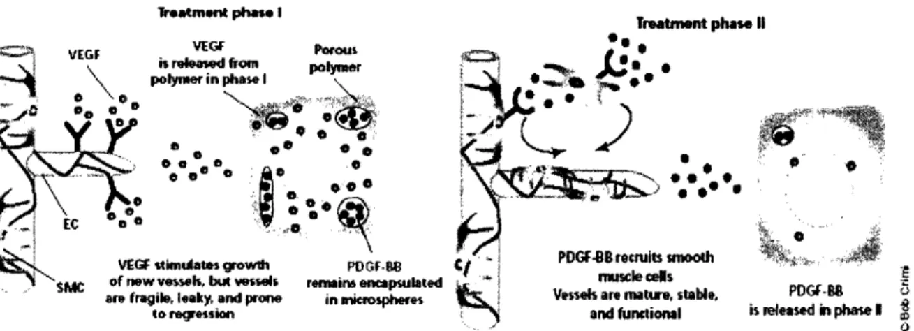
system that can control the release of multiple cytokines (Figure 4). Furthermore, the release of these signaling molecules can occur at different, predetermined rates 23. The variable kinetics of the system is achieved by imbedding polymer microspheres within a larger polymer scaffold. This system can be used to deliver VEGF and PDGF to a specific location in temporal sequence. The VEGF-infused scaffold slowly degrades by hydrolysis, releasing the VEGF molecule at a controlled rate. When this polymer system has degraded sufficiently, the PDGF-containing microspheres are exposed. The subsequent rapid hydrolysis of the microspheres then releases PDGF-B in a timely
manner. In vivo studies of this technology have resulted in a high degree of neovascularization and maturation.
Treatm.t phase I
VIEGF
1 tstknulaes growth w vessls, but vessels
are regiue, leasy, an prone
Treatment pi o . Porus Polyar \ PDGF-IB renmins encapsulated in miospheres has. II PDCB 5
Figure 4. Heterogenous Polymer Controlled Drug Release System23. The controlled release kinetics of two angiogenic factors aids in the engineering of mature vessels. Intially, VEGF is released which induces EC proliferation and angiogenesis. In the second phase, PDGF-BB is released to recruit SMCs, which are necessary for blood vessel maturation.
Gene Transfer for Use in Therapeutic Vascular Growth. Gene therapy provides a possible
alternative for in vivo vascular growth. Therapeutic vascular growth using gene transfer uses the standard strategies and exhibits near-identical characteristics and benefits as traditional gene therapy procedures. Adenoviruses are the standard vector for gene delivery and insertion. However, gene therapy for vascular growth aims to produce increased amount of cytokines and chemokines such as various types of VEGF, placental growth factor (PLGF), fibroblast growth factor (FGF), and angiopoiteins-4. Therapeutic vascular growth has also focused on both the constitutive and inducible expression of other factors involved in vascular growth including the multifunctional protein, hepatocyte growth factor (HGF). Another potential strategy is to induce cellular genes that, in turn, stimulate angiogenesis via a number of signal transduction proteins or transcription factors. This goal can be accomplished through the targeted insertion of genes that code for transcription factors such as nitric oxide synthetase (eNOS), inducible NOS (iNOS) and hypoxia-induced
I
A,
transcription factor (HIF-1). One potential benefit of using gene transfection is the selectivity towards inducing angio- and ateriogenesis, but not lymphangiogenesis. As with most gene therapy applications, there are significant problems in gene transfer efficiency in large mammals.
Nonetheless, gene therapy for vascular therapies has been able to overcome other traditional barriers of treating monogenetic disorders and, as a result, has shown positive results in some animal models. For example, preclinical wound healing models have shown the enlargement and proliferation of the capillaries when treated with adenovirus-mediated delivery of VEGF for more than 4 weeks. If the treatment were stopped before this critical time period, the vessels would regress.
Blood Vessels Derived From Stem Cells. Traditional tissue engineering strategies have focused
on utilizing differentiated cell types for regeneration of specific organs and tissues. For example, chondracytes are used for cartilage and hepatocytes are used for liver engineering applications, respectively. However, the recent developments of human embryonic stem (hES) cells have opened the door for new, exciting tissue engineering strategies. hES cells have the potential to differentiate into various types of cells. Therefore, they may be a useful source of cells for tissue engineering applications. A procedure that isolated hES cells using an antibody for PECAM1 was recently reported2 5. In vitro techniques have induced the newly differentiated stem cells to produce conformal geometries as well as cellular markers that similar to ECs. Stem cells have also differentiated
controllably to produce blood-containing vascular microstructures in vivo. This discovery may prove to be effective in engineering new blood vessels and treatment of regional ischemia. However, this advancement may also set the groundwork for engineering mature blood vessels by selectively differentiating hES cells thereby creating a co-culture environment. By precisely controlling the delivery concentration of cytokines and chemokines in the cellular microenvironment using
EC cells and mesenchymal cells, which are necessary for blood vessel maturation, in close proximity to each other.
1.3.2 Cell-Matrix Interactions for Vascular Tissue Engineering
Controlling cell-matrix interactions with synthetic biomaterials can induce desirable in vitro cellular responses. This approach exhibits often-significant advantages over the in vivo delivery of growth factors and cytokines. For example, more recent work with stem cells has focused on the formation and organization of hES cells into more complex three-dimensional vessel networks using porous biodegradable scaffolds26. These scaffolds, which were fabricated out of poly(L-lactic-co-glycolic acid) (PLGA) and poly(L-lactic acid) (PLA), provide physical cues for stem cell differentiation while also allowing sufficient void volume for proliferation and remodeling activities in cells. After seeding the polymer constructs with actively differentiating hES cells, they were cultured in the presence of various growth factors for several weeks. Depending on the growth factor, the cells exhibited properties similar to various developing tissues types including neuronal, cartilage, and liver. Furthermore, the hES cells were also shown to differentiate and organize into 3D vascular networks, which was supported by successful CD34 staining. When the cell-seeded construct was implanted into SCID mice, not only did the cells remain viable, but they were recruited by the host vascular system as they continued the in vitro progression and differentiation.
General Strategies for in vitro Vascular Tissue Engineering. Inducing the growth and
maturation of blood vessels can be accomplished in vivo as a direct therapeutic approach or in vitro using both traditional and non-traditional tissue-engineering methods. Presumably, the goal of in
vitro tissue engineering is to successfully culture vessels for eventual implantation into a host. There
are wide ranges of general strategies that can be used for creating viable microvasculature. One traditional approach is to culture cells on a biodegradable polymeric scaffold. After two months of
perfusion, the newly grown tissue can be implanted into the host. This strategy has proven to be successful in the growth of functional arteries27. In this system, ECs and smooth muscle cells (SMCs) were cultured on poly-glycolic acid (PGA) polymers in a biomimetic bioreactor under both static and pulsatile flow conditions. After 8 weeks of perfusion, the gross appearance of the cultured vessels was identical to that of native vessels. The wall thickness for vessels grown under pulsatile flow conditions was also significantly larger than those grown under static conditions. This result illustrates the importance of creating a biomimetic mechanical microenvironment for in vitro culture of vessels. These studies have demonstrated the potential of co-culturing SMCs and ECs directly rather than inciting the recruitment of SMCs by the ECs. Therefore, these vessels may not exhibit the ideal characteristics of a native, mature blood vessel.
1.4 Applications of Microfluidic Devices for Tissue
Engineering
Tissue engineering bioreactor technology is sufficient for culturing single blood vessels with diameters on the order of 1 mm or greater. These systems lack the spatial resolution and features for culturing complex networks of blood vessels. However, the rapidly growing field of BioMEMS enables the creation of microfluidic systems that can be modified to culture endothelial cells. Silicon etching has been used recently in the fabrication of microfluidic bioreactors for engineering tissues of various types 8. Endothelial cells were cultured in silicon microchannels that were capped with pyrex glass (Figure 5). Viable cell monolayers were successfully removed from the microreactor and implanted into rat omentum. This process was also demonstrated in the culture of hepatocytes28. Silicon etching is also applicable to the fabrication of microfluidic masters for use in replica molding. Poly(di-methyl siloxane) (PDMS) is an inexpensive elastomer that is often used in the fabrication of microfluidic devices for a variety of applications including tissue engineering2 9. PDMS-based
microfluidic systems have been designed to mimic microvascular structures and flow geometries for use a vascular tissue engineering bioreactor3 0. The microchannels in the device were coated with
synthetic ECM peptides to aid in cell adhesion of cells and provide an angiogenic cue. The device is seeded with endothelial cells and perfused in a continuous fluidic circuit. After several weeks in culture, the ECs tend to proliferate and form junctions as the channels become confluent.
Microfluidic devices have also been fabricated from PLGA' 1. However, this material is not desirable for a tissue engineering scaffold for reasons outlined later in the text. Nonetheless, the advantages of using such a microfluidic system are immediately obvious. The channel geometries can be constructed in such a way to mimic physiological geometries and length scales of blood vessels. Consequently, the fluid mechanic microenvironment can be controlled with great precision.
Manipulating geometries on the sub-micron can lead to new abilities in guiding tissue formation and regeneration by inducing selected cellular responses. This newfound control can be expanded to other types of tissue engineering including the culture of hepatocytes. Complex methods and devices have also been developed more recently using PDMS microfluidic systems.
Three-dimensional PDMS microfluidic devices have been fabricated for the perfusion culture of a liver cell model3 2. The high gas permeability of PDMS allowed for high-volume tissue engineering constructs while maintaining sufficient oxygen concentrations. Micropatterning of co-cultures for vascular tissue engineering applications has also been achieved 33. The deposition of three-dimensional cell layers has been demonstrated in PDMS microfluidic devices. A layer-by-layer approach to
microfluidic patterning of heterogeneous cells and matrices can lead to the co-culture of ECs, smooth muscle cells, and fibroblasts. This technique could provide strong angiogenic and maturation cues due to the potential for cross-talk between the different cell types. However, the disadvantages to using silicon or PDMS as a biomaterial platform are obvious. Neither silicon nor
PDMS is biodegradable or exhibit in vivo biocompatibility. Therefore, synthesizing and manipulating application specific biomaterials is a necessity for tissue engineering.
Figure 5. Perfusion Culture of ECs in Silicon Micromachined Networks2.
Engineering mature blood vessels is complex task that requires an interdisciplinary approach. First and foremost, the biochemistry of the tissues must be continue to be elucidated in order to
determine the relevant signaling molecules and the subsequent cellular pathways that are triggered. Various chemical, mechanical, and metabolic microenvironments have been shown to induce a wide range of angiogenic, anti-angiogenic, and maturation pathways. Eliciting the desired cellular
responses requires precise control over the presence of specific biologically active cytokines and the cellular microenvironment as a whole. Recent innovations in micro-technology, advanced materials, drug delivery, and tissue engineering have enabled the precise manipulation of virtually all aspects of the cellular microenvironment. Microfluidics has shown exceptional promise due to the
Therefore, microfluidic scaffolds enable one to indirectly incite a large set of desired cellular responses to direct or accelerate the in vitro growth of tissue or organs for regeneration applications.
1.5 Biomaterials
Polymeric, ceramic, and metallic biomaterials all play crucial roles in treatments and therapies of the medical industry. Specifically, biodegradable polymeric biomaterials have become instrumental in a wide range of novel technologies including drug delivery and tissue engineering. Recent
advancements have focused on synthesizing unique polymer blends with properties that can afford advantages for specific bioengineering applications.
1.5.1 Role of Biomaterials in Tissue Engineering
Biodegradable polymers have significant potential in the fields of bioengineering. They have shown promise in drug delivery, in vivo sensing, and tissue engineering, the latter of which is of extreme interest in this study 34. Biomaterials have been used in tissue engineering in the following ways:
1. The biomaterials are able to directly induce cellular migration and proliferation, which in turn results in tissue or organ regeneration.
2. Materials are used to encapsulate and segregate types of cell populations thereby functioning as a barrier between the implanted cells and the immune system.
3. Materials are fashioned into matrices used as a physical support for cell growth and organization into more complex hierarchal structures.
An example of the first approach involves the study of glycosoaminoglycan/collagen (GAC) constructs to stimulate healing and function as artificial skin. This approach has also been used in nerve and cartilage regeneration experiments3 5. The second approach fashions polymers into hollow
fiber membranes. Various types of cells can be placed within this membrane, which can then be implanted to treat a variety of organ failure problems3 6. This idea is also possible on a smaller scale. Macrocapsules fabricated from poly(acrylonitrile)-poly(vinylchloride) (PAN-PVC) membranes are able to encapsulate cells but contain pore sizes that are large enough to allow the transport of medium-sized molecules. The third application of biomaterials into tissue engineering utilizes a biodegradable scaffold to enable cellular proliferation and reorganization. Tissue engineering constructs made of biodegradable polymers are able to function as scaffolds for cell seeding and eventual implantation into a host3 7. One of the most widely studied polymers for this application is poly(D-lactic-co-glycolic acid) (PLGA), a biodegradable block co-polymer3 8. Substantial research has focused on fabricating a variety of scaffold geometries and compositions using PLGA. Sheets, fibers, and foams can all be produced and shaped into virtually any geometry. The large focus of work involving PLGA can be attributed in part to its FDA approval in addition to its various advantages. However, the fragile nature and poor mechanical properties of the polymer represent major limitations of PLGA as a biomaterial. Since most tissue engineering scaffolds will eventually be implanted into a biological system, the scaffolds will undergo many types of mechanical
deformations and stresses. In addition to potential for mechanical failure of PLGA-based
structures, exterior forces on an implanted rigid structure can cause local inflammation and scarring responses. As a result, ideal biodegradable tissue engineering scaffolds would be flexible with strong mechanical properties. Such a material would mimic the extracellular matrix (ECM), which is a tough, yet soft elastomeric network that provides stability and structural integrity to organs. Biomimicry of the soft ECM also reduces the effects of possible mechanical irritation to the surrounding tissues by allowing the implant to adjust to the dynamic stresses of the internal environment.
1.5.2 Existing Biodegradable Elastomers
Three classes of biodegradable elastomers have been previously reported: hydrogels3 9, elastin-like peptides40-42, and polyhydroxyalkanoates (PHAs) 43. Hydrogels are water-swollen cross-linked
networks composed of hydrophilic homopolymers or copolymers4 . Hydrogels have proven to be extremely useful in the pharmaceutical and medical industries because of their high water content and elastic mechanical behavior. The primary advantage of hydrogels is their high degree of biocompatibility. This property is due primarily to the fact that the majority of the volume (-90%) of hydrogel formulations is water. Also, the specific properties of hydrogels can be modified by altering such characteristics as the chemical composition, dilution, and cross-linking density. However, one major disadvantage of hydrogels is the lack of mechanical strength as most hydrogel formulations exhibit an ultimate tensile strength on the order of 100kPa45. Also, hydrogels may
exhibit a high degree of swelling which may prove to be useful in the synthesis of environmentally-responsive biomaterials. However, this characteristic limits the use of hydrogels as a material for fabricating biodegradable devices or structures that need to minimize swelling and maintain their geometry after implantation. Elastin-like peptides also show promise as a biodegradable elastomer. However, the method of fabrication is slow and expensive due to the need for genetic engineering of protein synthesis pathways. Producing large quantities of these proteins is also a time-consuming and costly endeavor. PHAs are inexpensive bio-polymer formulations that exhibit desirable
mechanical properties4 6. However, there are significant drawbacks including the potential for large amounts of endotoxins found in industrial samples. Also, only some of the monomers of PHAs occur naturally within the body. The biocompatibity of PHAs is also suspect. Subcutaneous poly(3-hydroxybutyrate) implants lead to a variety of inflammatory reactions47. Macrophages, neutrophils, lymphocytes, and fibrocytes were all found immediately surrounding the implant. Thus far, the
established biodegradable elastomers all suffer significant drawbacks for use as biomaterials in treatments and therapies.
1.6 Poly(glycerol-sebacate)
1.6.1 Shortcomings of Existing Bio-Elastomers
Pre-existing classes of biodegradable elastomers have proven to be advantageous in a variety of applications including implantable porous scaffolds for tissue engineering. However, the fabrication of microfluidic tissue engineering scaffolds is unable to benefit from any of these materials. An implantable fluidic device must be biodegradable, biocompatible, tough, flexible, and fabricated with micron-scale precision. Hydrogels are not suitable because of their relatively low tensile strength. PHAs are only slightly biocompatible and elastin peptides are expensive and time consuming to synthesize. Furthermore, none of these materials have been molded into geometries with micron-scale features. Although PLGA has been molded into microfluidic devices3 1, it is not flexible and could potentially cause scarring and inflammation upon implantation. Furthermore, PLGA has been shown to undergo bulk degradation in vivo, which results in microfractures and other defects that could impact the effectiveness of the device4 8.
1.6.2 Poly(glycerol-sebacate) -- "Biorubber"
Poly(glycerol-sebacate) (PGS) is a recently developed material that offers many significant advantages for use in the development of tissue engineering scaffolds. PGS is a tough,
biodegradable, elastomer that is biocompatible, inexpensive, and easy to synthesize. Inexpensive, ubiquitous starting materials and a bulk condensation polymerization process allow for large batches (-300 grams) to be synthesized. Sebacic acid and glycerol, the raw materials used in PGS synthesis, are found naturally in the body and have been FDA approved, respectively. In addition to these
advantages, PG-S exhibits the desired mechanical properties of high elasticity and high strength (Figure 6). These characteristics are obtained through low-density covalent cross-linking and hydrogen-bonding interactions, which also give collagen and elastin their strength and elasticity. The ultimate tensile strength is approximtaley 0.5 MPa, significantly higher than hydrogels.
1.0 0 l. 0.5 0) C
0
I-0.0 0 50
Figure 6. Stress Strain Curve of PGS
100 150 200 250 300
Tensile strain %
compared to other materials4 9.
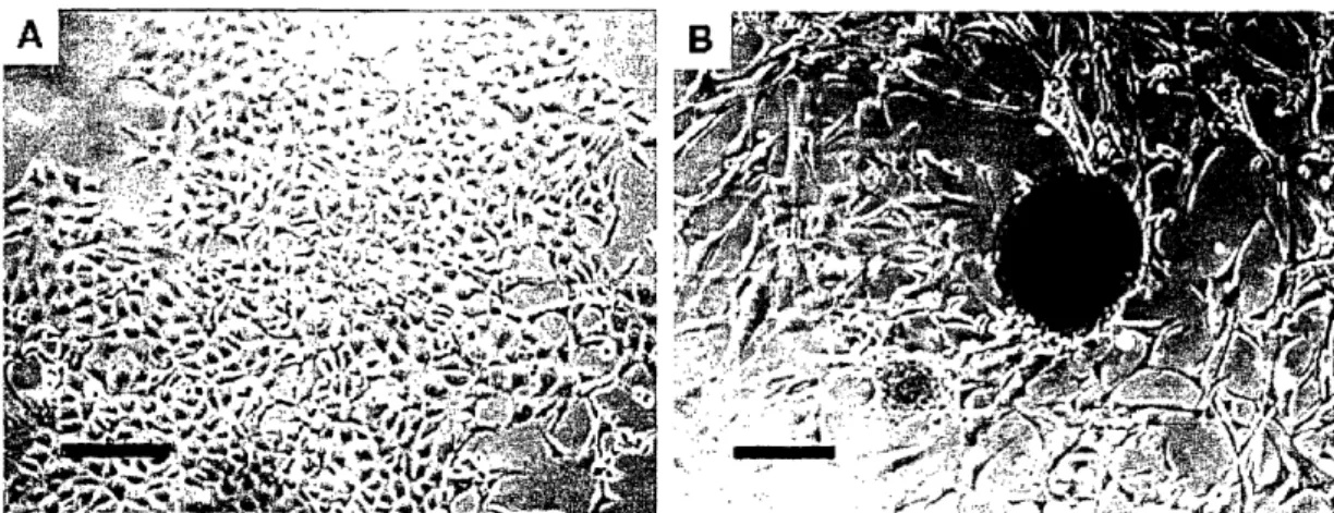
PGS is biocompatible both in vitro and in vivo. In fact, cells seeded on PGS layers in culture exhibit increased proliferation and improved morphology when compared to other types of biopolymer layers. For example, 3T3 fibroblasts grown on PGS layers had more adherent cells and cells with normal morphology when compared to PLGA layers (Figure 7). Subcutaneous implants of PGS sheets into rats also show reduced inflammation and scarring when compared to PLGA implants.
Figure 7. In Vitro Comparison of 3T3 Fibroblasts on PGS (A) and PLGA (B)4 9. Cells cultured on PGS layers exhibit increased proliferation and improved morphology when compared to cells cultured on PLGA layers.
The superior biocompatibility and mechanical properties suggest that PGS is a promising
biomaterial for numerous medical applications. The biodegradability and elastomeric nature of PGS make this material an attractive platform for developing a variety of tissue engineering scaffolds.
Chapter 2: Measuring Transport Properties of
Poly(glycerol-sebacate)
2.1 Introduction
Tissue engineering systems must be able to supply nutrients to cells seeded within the scaffold efficiently. As such, scaffolds fabricated out of various forms of PGS must be designed to overcome mass transfer limitations within the device. Therefore, one critical step in fabricating PGS-based microfluidic scaffolds is the assessment of the intrinsic mass transfer properties of the material. The transport characteristics of gases such as oxygen and carbon dioxide are especially important.
2.1.1 Rubbery vs. Glassy Polymers
There are two basic microstructural conditions of polymeric materials; the glassy and rubbery states. The mechanism of gas permeation through each of these types of polymers is very different. The main disparity between transport across rubbery and glassy polymers is due to the fact that glassy polymers are not in a true state of equilibrium. This non-equilibrium can result in significant differences in observed permeability and solubility coefficients. For example, diffusion coefficients in glassy polymers are highly non-linear functions of penetrant gas concentrations. Contrast this with the diffusion coefficients in rubbery polymers, which do not vary with changes in penetrant gas concentrations. Poly(glycerol-sebacate) our polymer of interest is a rubbery polymer at ambient
temperatures of' 22°C. Therefore, the focus of this transport study will concentrate on rubbery polymer systems. At temperatures above the glass transistion temperature (Tg, rubbery polymers are tough, flexible, which is associated with free chain motion50. Consequently, rubbery polymers have much shorter relaxation times, which allows them to immediately adjust to perturbations in
temperature or stresses. Rubbery polymers can therefore reach the new state of equilibrium very rapidly. This property is also applicable to the perturbation due to the absorption of a low
molecular weight penetrant. In general, the penetrant diffusion is much faster in rubbery polymers relative to glassy polymers because of this rapid relaxation time. Altering the physical properties of
the polymers, such as the crosslinking density, can modify the transport properties of both glassy and rubbery polymers. These alterations can, in part, lead to a wide range of experimental values when determining permeability coefficients. Therefore obtaining uniform PGS membrane samples will be of utmost importance when experimentally determining the relevant transport coefficients.
2.1.2 Theory
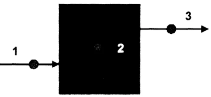
The mechanism of gas transport through a rubbery polymer membrane depends on many factors including the type of polymer. However, Graham's general solution-diffusion model suggests that
there are three unique phases of gas transport through a membrane"; 1) Adsorption onto the polymer surface, 2) Diffusion through the bulk polymer, 3) Desorption into the external phase
(Figure 8). These various microscopic mechanisms of gas transport can be manifested into three intrinsic macroscopic kinetic and thermodynamic properties; solubility, diffusivity, and permeability. The solubility coefficient is a thermodynamic property that relates the vapor pressure of the
penetrant to the concentration of the penetrant in the polymer. The diffusivity coefficient is a kinetic property that describes the ability of a gas to penetrate the bulk polymer. The permeability is defined as the product of solubility and diffusivity and describes the intrinsic mass transfer resistance for a gas in a polymer membrane (kn)". However, there are also mass transfer resistances associated5 with concentration gradients in the gas feed (kg,) and gas permeate (kgp) which may need to be factored into calculating the overall mass transfer resistance across the membrane:
1 1 I 1
= --- + -- + - (Eqn. 2.1)
Assuming that the mass transfer resistance in the gas feed and permeate sides is negligible, the equation can be reduced to:
K,, = km (Eqn. 2.2)
In other words, the permeability coefficient, P, relates the flux J and concentration gradient AC of the permeant species across a membrane of thickness , which is shown in the following expression.
J= PAC (Eqn. 2.3)
For an ideal polymer system such as a rubbery polymer, these transport properties are constant with respect to pressure and concentration. PGS is classified as a rubbery polymer and, as a result, exhibits ideal transport behavior. Therefore, gas adsorption onto the polymer surface can be described by Henry's Law, which takes the following form:
C = S p (Eqn. 2.4)
where C is the concentration of the gas in the polymer, S is the solubility coefficient, and p is partial pressure of the penetrant in the gas phase. Diffusion of the gas in an ideal polymer occurs by the gas molecules creating channels and activating polymer chains within the bulk. These processes can be described macroscopically through the Poisson equation for mass transfer without reaction:
ac
=
-D. V2 (Eqn. 2.5)at
This equation can be simplified for one dimensional diffusion to yield the following expression:
ac
02c
a
= -D
(Eqn. 2.6)
is the concentration of the penetrant at time t and position x. where D is the iffusivity and c is the concentration of the penetrant at time t and position x.
3
* a
1
Figure 8. Three Stages of Gas Permeation. 1) Solution in polymer phase, 2) Diffusion across bulk polymer, 3) Desorption from polymer into external phase.
2.1.3 Measurement of Gas Permeabilities
One method of experimentally measuring the permeability coefficient P and the diffusion coefficient
D of gases in polymer membranes is through a time-lag experiment5 2. These two properties can be used to calculate the solubility coefficient S, by the following relationship.
P
S = - (Eqn. 2.7)
D
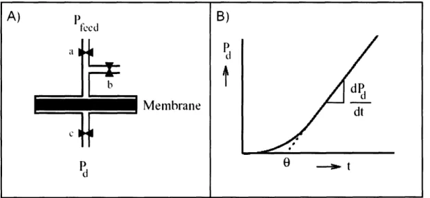
This technique begins by positioning the membrane in a diffusion chamber such that there are separate upstream and downstream sides (Figure 9A). The membrane is initially evacuated of residual gases for several hours. At time t = 0, the permeant gas is supplied at the feed pressure Ped and feed concentration c, by opening valve a and continuous measurement of the downstream pressure Pd begins. A typical time evolution of downstream pressure Pd versus time t is shown in
Figure 9B. Each experimental curve consists of both a transient state and a steady state. If an ideal membrane is free of penetrant at the start of the experiment, the amount of penetrant (Qt) passing through the membrane in time t is given by53:
Q.
Dt _I _2 (
-)
expD
2t1 (Eqn. 2.8)IDc -6DI 2 (Eqn. 2.9)
A simple linear extrapolation of the steady-state region, can be used to determine the time-lag
, which can be used to calculate the diffusivity coefficient D via the following equation.
D = 6 (Eqn. 2.10)
68
The steady state of the pressure versus time plot is used to calculate the permeability in a straightforward manner by manipulating the steady-state flux equation into the following form:
P= - l . VdMgaT dPd (Eqn. 2.11)
Pf,,eed p. RT.A dt
in which Pfeed is the upstream penetrant pressure, Vd is the downstream volume, Ma, is the molecular weight of the penetrant gas at density p, and A is the membrane area. As previously mentioned, the
Figure 9. Time Lag Diffusion Experiment. A) Schematic of diffusion chamber with upstream and downstream valve networks. B) Time-evolution of downstream pressure
(Pd). The steady-state slope of this profile is used to calculate the permeability of the
membrane while the extrapolated time-lag 0 is used to calculate the diffusivity. The solubility of the membrane can be calculated directly using Eqn 2.7
2.2 Experimental Methods
2.2.1 Time-lag Diffusion Experimental Apparatus
A schematic of the experimental set-up for measuring permeation by time-lag measurements is shown in Figure 10. The diffusion chamber is fabricated from two separate and identical pieces of 2024 aluminum (McMaster-Carr) that measure 3" x 3" x 1". Each piece contains a threaded inlet/outlet port, gas exchange chamber, porous supports for the membrane sample, and thru-holes for machine screw fasteners. The membrane sample is placed over the gas exchange area between the two aluminum pieces. A Viton R double-seal O-ring (McMaster-Carr) was placed around the outer diameter of the PGS membrane, which sealed off the sample from atmospheric gases. The upstream side of the diffusion chamber was connected to a poly(tetrafluoroethylene) (PTFE) tube
A)
P f
)
tlco
B)
P
t
Membrane~~
Memibrane
I
dP
ddt
0
P
dI . --C
using Swage-Lok fittings. The pressure of the gas feed was regulated by a multi-stage regulator connected to a A/4" rubber hose complete with a Swage-Lok connection. The downstream side of the diffusion chamber was connected to a 1/8" NPT chrome-plated brass tube. The transducer used for pressure measurements was an MKS 902 Series Piezo Transducer with a K16 adapter by HPS Products. The pressure signal was recorded by a National Instruments 6035 DAQ card and inputted into LabVIEW 5.0. The vacuum source was supplied to the system by using a Welch 1402
DuoSeal Belt-Drive vacuum pump which was rated to 3 microns. The vacuum line consisted of /4"
rubber tubing connected to a stainless steel ball valves (McMaster-Carr) using a hose barb connection.