Axially Force Limited Grinding Spindle for Robotic Grinding
byAustin Brown
Submitted to the
Department of Mechanical Engineering
in Partial Fulfillment of the Requirements for the Degree of
Course 2-A: Bachelor of Science in Engineering as Recommended by the Department of Mechanical Engineering
at the
Massachusetts Institute of Technology
June, 2018
2018 Massachusetts Institute of Technology. All rights reserved.
Signature
Signature of Author:redacted
Department of Mechanical Engineering May 11, 2018
Signature
reaactea
Certified by:
Accepted by:
Alexander H. Slocum Walter M. May and A. Hazel May Professor of Mechanical Engineering
Signature redacted
Thesis SupervisorMASSAH EHTTS IN TUE
OF TECHNOWOGY
SEP 13' 218]
co
wL
Rohit Karnik Associate Professor of Mechanical Engineering
Axially Force Limited Grinding Spindle for Robotic Grinding by
Austin Brown
Submitted to the Department of Mechanical Engineering May 9. 2018 in Partial Fulfillment of the Requirements for the Degree of
Course 2-A: Bachelor of Science in Engineering as Recommended by the Department of Mechanical Engineering
Abstract
Grinding and Polishing of small parts is often easily performed by human hands, yet is challenging to automate. The grinding and polishing process is best done using a force-control scheme, which human hands perform naturally. Heavy robotic arms, which favor a position-control scheme, are difficult to position-control precisely, and trajectory errors can cause excessive grinding force which leads to burning of the part or destruction of the grinding wheel. Prior art of direct force control on a large robot arm requires the end-effector to have a 6-axis
dynamometer, which is unwieldy, costly, and greatly limits the speed/precision of the process. We will discuss a new type of grinding spindle which is axially compliant, allowing the position-control robot arm to be used in a position-control nature. The spindle has a disjoint
force-displacement curve, effectively operating in two modes: position-control mode at first, until a critical force is exceeded, when the spindle transitions into force-mode, keeping constant grinding force on the part though a certain range of travel. This limits the amount of force which can be imparted during grinding to a safe amount. The spindle is very simple and mechanically robust. We have built this hybrid position-force control spindle and tested it. The spindle was shown to perform correctly and successfully completed the test grind.
Thesis Supervisor: Alexander H. Slocum
Table of Contents
Introduction ... ... 4.. 4
Background...4
Functional Requirements of Proposed Grinder.. -... ... 5
Concepts, Strategy, and Solution .. -... 5
A xial Force-Lim iting M echanism s ... 6
F lexure-based G rinde r ... . 6
A ir B earing G rinder, D esign 1... 8
A ir B earing G rinder, D esign 2 ... 9
P re lo a d M e c h a n is m s ... 10
S p rin g P re lo a d ... 1 0 G ra v ity P re lo a d ... 1 1 D e s ig n o f F in a l G rin d e r...12
Analysis of Proposed Design ... ... 13
Testing Mechanism...15
Fabrication... ... ... ... _...._. ... 17
Testing..._ ... _... ... 24
T e sting fo r C o m p lia n ce ... 2 5 G rin d in g a D isk ... 2 8 R unout M easurem ents ... . 34
Introduction
Today's world demands increasing automation. Nearly every field is turning towards automation to produce products at higher volumes with lower costs. Manufacturing is a sector which is moving increasingly towards full automation. However, new technology presents new problems. One manufacturing area which is looking towards increased automation is the grinding and polishing of watches. Watch grinding requires high dexterity and skill. The
workforce is aging without being replaced. One promising option for automation is to replace the humans with robot arms. Robot arms are incredibly versatile, meaning that a large number of operations can be performed by a single arm, and that the arm can be repurposed for other operations if products change.
However, robot arms are generally not very precise when they most fast: robot arms have very low control bandwidth compared to other machining machine types, and therefore at high path speeds precision suffers greatly. A robot arm's low bandwidth is due to the high moving mass and cantilevered nature of the robot arms. Robots have versatility at the cost of accuracy and control bandwidth. This means that any motion will have small trajectory errors, with the problems becoming worse at higher speeds. In the case of grinding, the grinding wheel is usually rigid, and so small trajectory errors can cause huge forces to arise. Huge forces result in many problems, most likely destruction of the grinding disk. Compliant grinding media, such as belts, can be used to polish, but have difficulty achieving accurate parts.
Ideally, a hybrid force-position control scheme could be implemented for robotic grinding. A final shape of workpiece is desired, which requires position-mode control, but grinding cannot be done with excessive forces, which requires force control. Prior art of force-control bolt grinding was done with a 6-axis dynamometer mounted to the end of the robot arm, between the end of the arm and the workpiece [1]. This solution is effective, but very costly and requires changing the robot controller. The robot arm can still not operate at very high speed, because even with force feedback, the robot arm is too heavy to quickly react. One solution is just to just slow the entire process down, but then the robot can no longer compete with a human.
Background
Grinding is the process of machining using an abrasive wheel to remove material. The workpiece is brought into contact with the abrasive wheel and the workpiece is slowly eroded
away. Grinding can be used to achieve micron precision. Polishing is a variant on grinding, where the goal is to smooth the surface of the workpiece, usually for aesthetic reasons. Both
processes can be done easily by machines. Force-control is a control scheme in which a force is controlled to be the desired parameter, in this case force control can be used to keep
constant grinding force between the part and the surface of the grinder. In force control, the position is allowed to be whatever it needs to be to achieve the desired force. In position control, the precisely the opposite is true: the force is commanded to whatever it needs to be to achieve the desired position. In the case of the discussed grinding problem, the ideal control scheme is position-mode control with force control built in to ensure forces to not become too high.
Conventionally, grinding is done with incredibly precise position-control to circumvent this force-control problem. An example of this is a surface grinder, where the grinding wheel is
lowered with micron precision until it touches the part, where then a precise amount of material is removed. The incredible precision of the surface grinder does not experience excessive forces because material removal is so tightly controlled. However, with a robot arm doing the grinding, the problem that arises is that inaccurate position-control on robot arms dictates a force which is too high for the grinding process to safely undertake. Even with prior art of a six-axis dynamometer mounted to a robot arm, the robot arm does not have high enough bandwidth to grind parts accurately at high speed while keeping limits on the desired force.
High forces arise in this situation because there is no compliance in the structural loop of the whole system. We have solved this problem by allowing a precise amount of compliance in the structural loop. We have introduced compliance at the grinding spindle, and ideal place to add compliance as the robot arm is left unchanged, and the bandwidth of the system can be high as moving mass is low.
Functional Requirements
The first functional requirement for the hybrid position-force control grinder is that the grinder must function as a grinder. The unit must possess an abrasive cutting surface which moves past the workpiece at a high speed. The grinding wheel must stay relatively flat to grind the workpiece precisely. The grinder must resist sudden shock loads, as the environment it is operated in is rough-and-tough. The grinder must implement the novel hybrid position/force control scheme: it must maintain a precise position for any force between zero force and the breakaway force, with high stiffness, but when the breakaway force is exceeded, the device must maintain a constant grinding force for a range of positions. The grinding force in the force-control regime must be relatively linear. The moving mass of the grinder must be kept relatively low, to ensure high force control bandwidth. From a usability standpoint, the grinding abrasive must be easy to attach and replace. The abrasive must also be firmly mounted, as compliance in the grinding abrasive will cause strange effects in the position-control mode. The mechanism must be relatively simple to build and service. The grinder must use components that are impervious to grinding dust.
Concepts, Strategy, and Solution
Several strategies were proposed to implement the hybrid position-force control scheme on the grinder. The solution must satisfy the functional requirements. The largest design
decision was how to simply implement hybrid position-force control without ungainly complexity. This control scheme could be implemented either electronically with sensors and actuators, or entirely mechanically. A mechanical approach was selected, with the electronic approach being saved for future work. Several concepts were proposed to create the mechanical position-force control scheme. The basic layout for all concepts proposed is the same: A disk covered in abrasive media is preloaded forward against a hard stop. The disk will stay against the hard stop until the preload force is exceeded, causing the disk to move back away from the workpiece.
The first concept involved an axially-compliant flexure on top of a rotating spindle. This method separates the linear motion and the rotary motion, compartmentalizing the modules. An adhesive-backed sanding disk would be attached to the face of the disk. The flexure mechanism allows for axial compliance with rotational stiffness. This solution was ultimately not selected due to greater complexity than other solutions.
The second concept involved an axially-compliant shaft supported by three air bearings. Two air bearings of identical ID would fit around a precision shaft, enabling rotation without axial constraint. The third air bearing is a doughnut-shaped thrust air bearing, which prevents motion in one direction by abutting a precision surface on the back of the main shaft. This surface also serves as the drive pulley for driving the rotary motion. A precise preload force is applied to keep the thrust flange against the thrust air bearing. When the preload force is exceeded, the pad simply lifts off the air bearing. This finely allows for the two modes of operation: position-mode when the thrust flange is in contact with the air bearing, and force position-mode when the flange is not in contact and only being forced with the preload force.
The third strategy involved a simplification of the second strategy, combining the back rotary air bearing with the thrust bearing into a combined radial-thrust bearing. This would have been a very nice and elegant solution. Ultimately this solution proved infeasible as off-the-shelf air bearings do not come in the same size radial and combined radial-thrust.
N
Figure 4: Cutaway of grinder with combined radial-thrust bearing. Air bearings colored blue.
The second strategy for hybrid position-force control was selected going forward.
The next step was to determine the preload mechanism, to preload the grinder up against the thrust air bearing. Two options were floated: a very light grinder with spring preload, or a heavier grinder with gravity preload.
The first option involved a grinder with very light moving mass and a spring preload, with the goal of keeping as high axial bandwidth motion as possible. This would allow for very high-speed axial acceleration, satisfying the functional requirement of keeping constant force under many operating regimes. The light-mass grinder would be particularly beneficial for grinding as fast as possible. One way to implement this spring preload mechanism was through the use of a flat piece of spring steel pressing on a tooling ball. The tooling ball was mounted to the end of the shaft and the piece of spring steel was mounted to the frame. Below is a model of what such a grinder could look like. Note the pocketed disks to reduce the moving mass.
Figure 5: Design of spring preloaded spindle. Spring mechanism made of tooling ball and flat plate of spring steel.
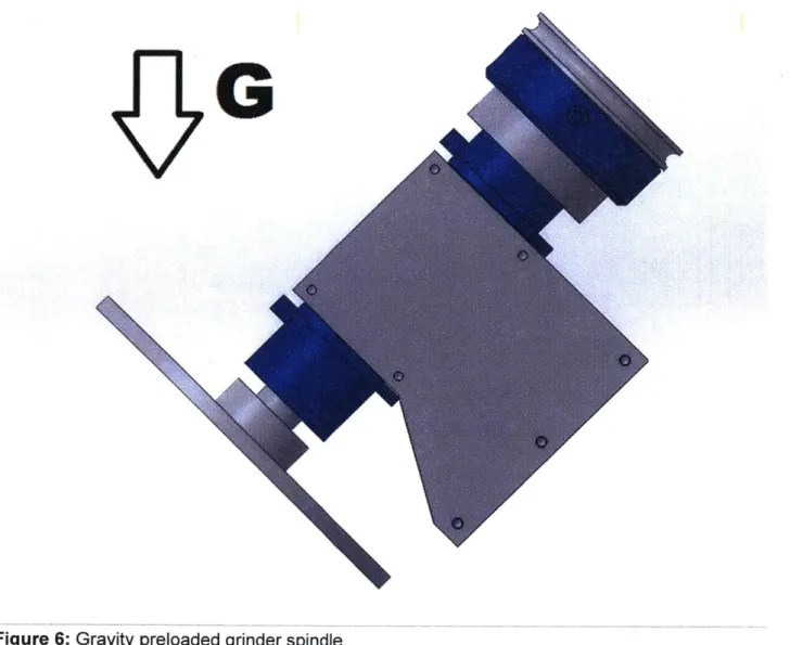
The second strategy for preload was a simple gravity preload. Instead of using a spring to preload the mechanism axially, the whole grinder could simply be mounted at an angle, such that a component of gravity would preload the mechanism. The downside to this strategy was that the bandwidth of the device suffers heavily compared to the lighter spring-based design, as the device must be heavy enough to preload itself. However, gravity preload was ultimately selected as it is much simpler than a spring-based mechanism.
G
L
6 0
0
0
C/
Figure 6: Gravity preloaded grinder spindle.
The final CAD model of the grinder is pictured below. The grinder frame is made from a solid billet of aluminum. The two radial air bearings are secured into the block with epoxy. The thrust air bearing mounts on a small spacer plate, again through epoxy. The motor selected to drive the unit is an Andymark, Inc. CIM motor, commonly found in FIRST robotics kits. Power is transmitted to the main shaft through a belt on two pulleys. It must be noted that the grinder shaft pulley will move in and out, as this shaft moves axially. A circular belt profile was chosen as this is very tolerant of misalignment. The grooves on the pulleys are large, further helping tolerate misalignment. A simple rubber O-ring will be used as a belt. The pulley and the thrust bearing surface are the same piece. The grinding disk is held to the front of this shaft through the use of a screw-on clamping coupling, so that the grinding disk could easily be removed. The rotation direction was set to tighten this coupling during operation.
Figure 8: Design of final grinder, side view.
Analysis
In parallel to the design of all geometric models, a mathematical model of the device was made through the use of a comprehensive spreadsheet. The mathematical model was used to determine the performance of the machine, and validate design decisions.
The spreadsheet was used to calculate these key values: Radial air bearing loads
Belt tensioning
Spindle speed for proper grinding SFM
Whether or not the air bearings will be edge-loaded Thickness of spring steel if used for spring
Device resonant frequency if using a spring for preload
The most important calculation was to verify was that the radial air bearings would not be overloaded and bottom out, causing rapid wear and prompt destruction. Radial loads on the air bearings are created as a result of axial grinding force, tangential grinding force, and belt
tension. A piece of steel was taken to a bench grinder and a hard roughing grind was
performed. The normal and tangential grinding forces were both estimated to be approximately 15N. This was a hard roughing grind, so if the grinder could survive this, it would certainly be good enough for our needs. The belt tension required was mathematically calculated to be 24N (will be discussed in more detail later). The mass of the grinder was ignored in this calculation. This was acceptable because the mass is relatively low (less than 1 kg) and does not create strange moments on the air bearings as the other forces do. 3/4" air bearings were selected as the lab happened to have two extras. Under these conditions (1 5N normal, 15N tangential, and 24N of pulley preload, 3/4" air bearings) the radial air bearing safety factors were calculated to be 5.3 and 4.1 for the front and rear air bearings, respectively. This is certainly good enough for the purposes of this grinder. It should be noted that the whole purpose of the grinder is so that excessive forces cannot be generated, so this is a very safe estimate.
The next important calculation was to determine the belt tension necessary to transmit the motor torque to the shaft without belt slippage. The proposed solution involved using a 1/8" diameter cross-section rubber o-ring as a belt. This would be riding on a smooth aluminum pulley surface. A conservative coefficient of friction of 1 was estimated. The torque required drive the unit at the disk is 0.75Nm. The sizes of pulleys were taken from the CAD model. From all these parameters, the capstan equation was utilized to calculate the safety factors on each pulley for transmitting the required amount of torque. Both pulleys had a safety factor of 2.3, well within safe limits. The belt tension was originally 20N, however this proved inadequate as it would result in negative tension on the slack side of the pulley. Therefore the belt tension was adjusted to 24N. It is likely that this is a very conservative estimate as the coefficient of friction is almost certainly higher than 1 with clean rubber on smooth aluminum. Additionally, the vee-groove nature of the pulleys increases their effective coefficient of friction, and even if the belt does slip slightly no major problems will arise.
The next calculation was the grinding speed. A linear speed of 5000 SFPM (surface feet per minute) was desired, or 25 m/sec. This corresponds to a rotational speed of approximately 4800 RPM, grinding at a distance of 2 inches out from center (for a 6" grinding disk). The pulley ratio selected was approximately 1:1, so the motor will have to spin at approximately 4800 RPM as well. The motor selected, the Andymark, Inc. CIM motor, in fact has exactly this as its no-load speed at 12 volts, meaning that the CIM motor will have to be driven at a slightly higher voltage to increase the speed. The author has a great deal of experience running similar motors at much higher voltages than designed, so a 20-50% boost in voltage is not a problem as long as the motor has good cooling which it does in this case. It is also very unlikely that the grinder will be operated at the full 15N of grinding force at 100% duty cycle. The power required to run the grinder at full load was also calculated to be 380 watts. This is just fine for a motor of the size of the CIM.
The next calculation was to ensure that the air bearings would not be edge-loaded. Edge-loading is a scenario when the shaft running through a bearing is deformed in such a way that loads are not distributed over the bearing, but rather concentrated on the outside edge. When this occurs in a fluid bearing, the result can be that the fluid can no longer keep the shaft off its surface and the shaft bottoms out. This is obviously extremely detrimental, especially in the case of the fragile graphite surface on an air bearing. Edge loading was analyzed in the back bearing, where the pulley preload is cantilevered fairly far from the radial bearing to make
space for the thrust bearing. Edge-loading is fairly complicated to model, so a worst-case scenario was used. The shaft was treated as a simply supported beam, hanging from the CoS of the device (directly between the two radial bearings) with a load applied to the tip by the pulley preload. Under the pulley tension load of 24 N, the deflection seen at the very end of the shaft (where the deflection is the greatest) was still less than the air-gap of the air bearings. As the air bearings are not mounted on the very end of the shaft, they will for sure not be edge-loaded.
The last two calculations were not used in the final device, but will be presented anyways. The first calculation was to properly size a preload spring. The preload spring geometry selected was to use a flat strip of spring steel pressing against a tooling ball on the end of the shaft. The proper thickness and length of spring could have been selected if we chose to go with this control scheme. The second calculation was what the resonant frequency of the device would be, to get an idea of the force-control bandwidth. The faster the resonant frequency, the faster the device could settle to a constant force after being subjected to an
impulse disturbance. This calculation was ultimately not used as with a gravity preload, there is no spring constant to use.
Test Setup
A setup for testing the device was necessary. The original plan was to use a real robot arm to perturbe the device, however this would have been exceedingly time-inefficient and costly. A better solution had to be devised to test the device and observe its performance. A simple solution was devised to meet the requirements. A second spindle was placed orthogonal to the grinding spindle, with a disk-shaped test part placed atop it. The grinder grinds the rim of this test disk as the test disk is rotated. The test disk is not a perfect circle. Instead, small bumps
are present along the rim. These bumps in the disk cause the grinder to push pack when the grinding force becomes too large. The bumps are slowly ground away as the disk rotates.
Ideally, all the high spots are ground away sequentially until the grinder enters position mode for a complete revolution of the test disk. In position-mode, the force will decrease to zero,
eventually stopping the grinding process. In industry this is referred to as spark-out. The disk will slowly become more and more circular as the high spots are ground away at the breakaway force, while the low parts are untouched. In the end the test part should have become a
perfectly circular disk.
The testing mechanism was made of another CIM motor, this one coupled to a 60:1 BaneBots, Inc. gearbox. The CIM motor was placed atop a large guide rail with a small lead screw on the side. This enables the test disk to be fed into the grinder slowly. An adjustable end stop can be used to feed in to a repeatable position. This stop can be moved along the 8020 for coarse adjustments and has a threaded bolt for fine adjustments. The entire assembly was made to fit straddled between two pieces of 1"x2" 8020 T-slotted framing. This assembly had 1" square 8020 legs to allow for angle adjustment, to adjust the grinding preload.
Figure 10: Grinder and test mechanism atop testing frame. Fabrication
Fabrication was relatively easy as many of the parts were easily manufactured on the Omax waterjet cutter in LMP. The main billet frame was outsourced to Protolabs. The 8020 beams were sawed to size and several various other parts were machined on the Bridgeport milling machine and the Hardinge lathe in the MITERS shop. Much of the time was spent on the lathe turning the pulleys. The motor pulley was pressure turned and then press-fit onto a hub, and the shaft pulley was turned to a precise ID, pressed onto the precision shaft, and then the outside and thrust faces were turned. Turning of the precision thrust bearing face was difficult and will be discussed more below. The test apparatus was in fact assembled inverted left-to-right, to better fling grinding grit away from the test guide rail.
The air bearing alignment though replication process was perhaps the most interesting part of the fabrication. First up was the radial bearing set. The hole in the main block was left
1 mm diametrically oversized. Masking tape was used to both center the bearings and act as a
dam to prevent epoxy from dripping into the cavity between the bearings. The epoxy used was JB weld original formula. This epoxy was selected over others due to its high viscosity, meaning that it would not run and drip into the air bearings, which would be an expensive mistake. To
precisely center and align the bearings, the air was turned on and the precision shaft inserted into the two bearings. A test fit was performed to ensure everything spun smoothly, which it did. Both the bearing outsides and the main block inside surfaces were lightly sanded and cleaned with acetone. To lock in the replication, both surfaces were coated in epoxy, with only a thin layer present on the main block to ensure most of the excess epoxy would end up on the outside of the block. The air was turned on and the shaft inserted. To the authors surprise, a scraping noise was heard and the air bearings began to expel themselves from the block, as air from the inside of the air bearings was pressurizing the internal cavity. This problem was not noticed during testing because the masking tape did not form an airtight seal, where the epoxy did. The solution was to quickly drill an exhaust hole right in the center top of the device. This solved the problem and the bearings were epoxied in correctly with perfect alignment. The epoxy was allowed to cure and the shaft spun beautifully.
Figure 11: Front radial air bearing secured into main block with JB weld.
The next step was to epoxy in the thrust bearing, again using master/slave replication. This turned out to be much more challenging than anticipated. The plan was to turn the
pulley/thrust flange part perfectly orthogonal to the shaft and then use it as a master surface to set the alignment for the thrust bearing. The critical thrust flange surface would be turned while pressed onto the shaft, while the shaft was held by a collet. However, unfortunately the collets
the author had were not precise enough to hold the shaft exactly straight. With the shaft held at a slight angle, the resulting thrust surface was not perfectly perpendicular to the shaft and therefore the shaft was not fit to use as a master surface. A better solution was needed than just a collet. The best solution would have been to put the shaft back into the lathe and turn a small divet to use a live center to precisely straighten the shaft, ensuring perfect perpendicularity in the final product. However, the pulley was already pressed on, and therefore the shaft would not fit back in the lathe. Instead the solution was to use the steady rest. The steady rest did not fit forwards, so it had to be used backwards to support the part. To avoid marring the shaft with the steady rest, a 3/4" ID ball bearing was used to support the shaft. This took two tries to get
perfectly orthogonal but eventually the shaft was dialed in straight.
Figure 12: Turning of the thrust flange face.
The thrust bearing flange face was turned as slowly as possible with a high-rake carbide insert. The resulting surface finish was impeccable, and the thrust air bearing floated beautifully.
Next up was gluing the thrust bearing in place. With the main shaft and precision turned pulley as a reference, they could be used as a master to precisely align the thrust bearing. Four small wads of paper towel were used as a way to loosely hold the air bearing against the thrust surface. When the bearing was satisfactorily centered and the shaft spinning well, the thrust bearing was secured in place with hot melt glue. Epoxy was not used here as the loads are not
as demanding, and because it is not as permanent. If the replication process did not work, the hot glue can be removed which is not a realistic option with epoxy. Epoxy can always be injected later for added strength, although for now it is not necessary.
Figure 13: Machined pulleys and hot-glued thrust bearing.
One problem which arose was the attachment of the front disk, which holds the grinding media (in this case a sanding disk). The original screw-on coupling method proved to be
problematic in several ways. First up, we were not using it in the way that the coupling was originally designed, and so the coupling was unable to secure onto the shaft with high force. A hose clamp was used to solve this problem.
Figure 14: Original coupling with hose clamp. Note the cut in the side- this coupling is not designed to operate without radial constraint, hence why the hose clamp was necessary.
The next problem, which was more serious, was that the disk could not be repeatedly held perpendicular to the shaft. The face of the disk was mounted to a lathe and faced on the front and the back, but when the coupling was removed and put back on the orientation was no longer true. A new clamping coupling was made to circumvent this issue, and a new disk was manufactured on the Waterjet cutter. This new disk was made of polycarbonate as ringing problems were experienced during facing of the aluminum disk, due to aluminum's poor inherent damping.
Figure 15: Final clamping shaft collar.
After these modifications the grinder spun perfectly, the disk was straight, and the device was ready for testing.
Figure 16: Grinder and test frame assembled. Note the inverted test setup, to fling grinding dust away from the testing mechanism guide rail.
Testing
Several mild steel disks with bumps were cut from 1/8" mild steel. The bumps were of various widths, but all were 5mm tall on top of a 7" disk.
Figure 17: Test disk cut made of mild steel, cut on the waterjet. Note the bumps.
The test part disks were attached to the CIM gearmotor, and a 400 grit sanding disk was attached to the polycarbonate front disk. The entire test setup was placed inside a box to
contain the grinding dust. The test mechanism linear guide rail was covered to protect it from grinding dust. The grinder was spun up at 12v and the test part fed in while rotating at
approximately 20 rpm. At 12v the grinder spindle spun up to only 4000 RPM. Stick-slip grinding occurred, which led to severe axial oscillations of the spindle. The voltage was increased to 16v, bringing the RPM to 6000, and the oscillations subsided. Revolution speed was measured with a laser tachometer. With this increased spindle speed the grinder worked as expected, and ground the test part very well. The axial compliance allowed the grinder to grind the test part with ease. Note the varying gap between the back of the shaft coupling and the front of the front radial air bearing as the grinding force exceeds the vertical component of the weight of the spindle shaft system.
The surface finish was extremely good.
Figure 21: Excellent surface finish on test part.
The material removal rate with the 400 grit disks was slower than expected, and the disks wore through after only about 5 minutes of grinding. This was likely because it was a very thin sanding disk not really designed for heavy material removal.
In the second round of testing, we desired to not only test the functionality of the compliance, but see the grinder it could be used to make accurate parts. To do this we started from a fresh lumpy disk, ground it circular, and measured the runout at the disk surface. The
runout of the test disk can be used to measure the accuracy of the grinder. Much stronger and rougher 40 grit sandpaper was used to rough down the lumps and then a finishing grind was performed with 400 grit sandpaper.
The first step in this test was to measure the runout of the gearmotor upon which the test disk will be mounted. If the runout of the final ground disk is on the order of the runout of the gearmotor, we can conclude that the error contributed by the grinding spindle is small, and that the grinder is in fact more accurate than the testing setup.
One problem experienced with the 40 grit grinding was that the forces experienced on the grinding disk were much rougher. The grinding forces were causing the test disk to jump around in the backlash of the gearmotor it rode upon. To mitigate this problem, foam was taped
between the grinding disk and the test assembly structure. The foam provided friction to slow the rotation and preloaded the gearbox enough to stop the bouncing.
Figure 22: Measuring the runout of the testing mechanism. The foam on the left of the image provides drag to preload the gearmotor.
The runout measured on the gearmotor, to which the test disk will be mounted, was 6 thousandths of an inch.
The test part was fed in and the grinding process initiated.
After approximately 5 minutes the lumps were appreciably worn.
Figure 25: Testing of grinder. Note the lump with flattened top.
After 20 minutes of grinding, the peaks were all completely leveled down. Twenty minutes is rather slow, but this time could most likely be cut in half if more preload or a coarser grit were used; however this would then require a higher power spindle motor. What is most important is the transition from force-control to position-control was very evident and occurred over just a few revolutions of the test disk. Changes were noticeable in the size of sparks, the current
drawn, and the audible noise from the device. All of these became noticeably smaller (by about half) when a peak of the test disk was completely removed and position-control took over. The surface finish of this grind was rough as the grinding disk was only 40 grit. After this roughing pass, 6 minutes of finish grinding was performed with the original 400 grit paper.
Figure 26: Ready for finishing operation of grinder with 400 grit sanding paper.
After 6 minutes of finish grinding, the maximum-to-minimum runout at the tip of the disk was measured to be 0.005", slightly less than the runout of the motor shaft alone. To see if this could be improved, the test disk was ground for another 10 minutes. The surface finish was ground to nearly mirror perfection, but the runout on the part observed was still 0.005", which is most excellent considering that the runout of the shaft supporting the workpiece was 0.006". It can thus be concluded that the grinder is at least as accurate, if not more, than the system used in this test. Future tests could be conducted with a more accurate workpiece spindle and a more accurate grinding disk to more accurately assess the capability of the system to produce precision ground parts.
Figure 27: Measuring runout of test disk.
Conclusions and Future Work
In this thesis, a solution to excessive forces present in robotic grinding is proposed. The solution consists of adding mechanical force limiting in the structural loop with a hybrid position-force control spindle. The spindle was deterministically designed to ensure feasibility. The spindle was then built and tested to observe operation. The axial force-limited spindle
successfully exhibited the desired axial force limit and ground an irregular test part without any burning or overload of the system, an operation which could not be performed with a regular axially rigid grinder. Next, testing was conducted to measure the accuracy of the grinder, and the grinder was verified to be at least as accurate as the testing setup, if not more. Future work could include adding sensors to detect spindle axial position, and testing with a real robot arm. In conclusion, this spindle represents a great advance in robot grinding capability.
References
1 ABB Robotics. "ABB Robotics - Grinding Forged Steel Parts." YouTube, YouTube, 31 Oct.
2012, www.youtube.com/watch?v=OMAT6sEipgE.
2 Slocum, A. H., Precision Machine Design, @ 1995, Society of Manufacturing Engineers, Dearborn, MI.
3 Slocum, A. H., FUNdaMENTALS of Design, and accompanying lecture videos and notes available on-line for free at (http://pergatory.mit.edu/2.007/resources/FUNdaMENTALS.html).