Publisher’s version / Version de l'éditeur:
Vous avez des questions? Nous pouvons vous aider. Pour communiquer directement avec un auteur, consultez la
première page de la revue dans laquelle son article a été publié afin de trouver ses coordonnées. Si vous n’arrivez pas à les repérer, communiquez avec nous à [email protected].
Questions? Contact the NRC Publications Archive team at
[email protected]. If you wish to email the authors directly, please see the first page of the publication for their contact information.
https://publications-cnrc.canada.ca/fra/droits
L’accès à ce site Web et l’utilisation de son contenu sont assujettis aux conditions présentées dans le site LISEZ CES CONDITIONS ATTENTIVEMENT AVANT D’UTILISER CE SITE WEB.
Research Report (National Research Council of Canada. Institute for Research in
Construction), 2006-03-01
READ THESE TERMS AND CONDITIONS CAREFULLY BEFORE USING THIS WEBSITE.
https://nrc-publications.canada.ca/eng/copyright
NRC Publications Archive Record / Notice des Archives des publications du CNRC :
https://nrc-publications.canada.ca/eng/view/object/?id=b16f1929-3c7a-437e-9ffc-10d2910764f9 https://publications-cnrc.canada.ca/fra/voir/objet/?id=b16f1929-3c7a-437e-9ffc-10d2910764f9 For the publisher’s version, please access the DOI link below./ Pour consulter la version de l’éditeur, utilisez le lien DOI ci-dessous.
https://doi.org/10.4224/20377185
Access and use of this website and the material on it are subject to the Terms and Conditions set forth at
Flanking Transmission in Multi-Family Dwellings: Phase IV
Nightingale, T. R. T.; Quirt, J. D.; King, F.; Halliwell, R. E.
Fla nk ing T ra nsm ission
in M ult i-Fa m ily Dw e llings
Pha se I V
Research Report 218, March 2006
T.R.T. Nightingale, J.D. Quirt, F. King, R.E. Halliwell
National Research Council Canada
Conseil national de recherches Canada
Executive Summary
The focus of this project is flanking transmission in wood framed construction. This report is the integration of results from four successive projects where the focus and construction details were decided by a Steering Committee formed from technical representatives from each of the supporting partners. Partners included Canada Mortgage and Housing Corporation, Forintek Canada Corporation, Marriott
International, National Research Council Canada, Owens Corning, Trus Joist, and USG Corporation.
Flanking transmission is sound transmission between two rooms by paths other than directly through the nominally separating wall or floor assembly. Flanking exists in all buildings and its importance in determining the apparent sound insulation (that perceived by the occupants) will be a function of the construction details of the walls, floors and their junctions.
The power transmitted by a flanking path is determined by five factors. Construction details investigated in this project changed one or more of the five factors:
1. Power injected into the flanking surface by an airborne or impact source; 2. Power attenuation from point of power injection to the flanking junction; 3. Power attenuation through the junction;
4. Power attenuation between the junction and the radiation point;
5. Conversion from structure borne power to sound power in the receiver room. The focus of the first three projects was flanking transmission involving the junction of a partition wall with a floor that had continuous structural elements that pass under the partition wall separating two dwellings. The fourth project provided an initial examination of the additional flanking transmission involving sidewalls and ceilings where the gypsum board was directly attached to the framing.
In all four studies, junction or surface(s) of interest were deliberately isolated to allow a systematic investigation of construction details that affect flanking transmission. Using this approach, estimates were obtained for the transmission paths – direct and flanking. With this information it is possible to rank paths by importance and combine the estimates for particular paths to obtain estimates of sound insulation for complete assemblies having a construction similar to that tested.
Page ii
The following observations are limited to the constructions examined by this study and are not necessarily applicable to an arbitrary construction:
• Except for situations where required for wind and seismic loads, building elements, such as OSB, gypsum board, joists, etc. should not be continuous across or under a partition as these can introduce strong flanking paths.
• Flanking paths involving gypsum board surfaces can be significantly suppressed by mounting the gypsum board on resilient channels. The effect is different for direct and flanking transmission. Mounting the gypsum board on resilient channels is more effective than adding another layer.
• Because of structure borne attenuation across the floor, the impact sound insulation was found to be very sensitive to the location of the impact source, for horizontally and diagonally separated rooms. For most toppings the NISPL increases (sound insulation decreases) as the source is moved closer to the flanking junction. This complicates comparing results from different studies.
Assemblies without a floor topping
• For room pairs separated by a partition wall:
> The dominant flanking path is from the floor in one room to the floor in the other room when the OSB subfloor, and/or joists, are continuous under the partition wall separating two rooms.
> When both the joists and the OSB subfloor were continuous, the apparent sound insulation was limited to Apparent-STC 38 – 39 despite the Direct-STC 52 potential of the wall. Increasing the sound insulation of the wall would be ineffective because the dominant transmission path does not involve the wall. > Flanking paths involving gypsum board surfaces, even those directly attached
are considerably less important than flanking paths involving a bare floor. • For room pairs separated by a floor ceiling assembly:
> The dominant flanking path for airborne and impact sound was from the subfloor to the wall in the lower room. The path from the upper wall to the lower wall was considerably less important. In real buildings there are typically four floor/wall junctions in every room, and the consequences of flanking transmission will be significantly worse than when there is only one. • For diagonally separated rooms:
> The dominant path was from the floor above to the ceiling of the room below on the diagonal, if the gypsum board ceiling was directly attached to the floor joists. If the ceiling was mounted on resilient channels then the dominant path tended to be from the floor to the party wall of the room below on the diagonal, if the gypsum board was directly attached to the studs. Paths involving the sidewall(s) were of little practical importance.
• For both horizontally and vertically separated rooms:
> The effect of joist orientation (parallel versus perpendicular to the flanking junction) was very important in determining the magnitude of flanking paths involving the floor.
• In comparison to the effect associated with joist orientation and continuity, junction blocking (details at the wall/floor junction) and joist type (solid lumber versus wood-I) were not particularly important. Wall type (single versus double stud) was important for horizontally separated rooms, but not for those vertically separated.
Floor Toppings
• A correctly designed and applied floor topping can effectively control severe flanking paths involving continuous elements.
• Topping effectiveness is determined by the sum of changes to all relevant transmission mechanisms. In particular:
> Direct transmission and flanking transmission are affected differently; > Airborne and impact sound insulation are affected differently; and
> The effect is strongly dependent on the construction of the floor to which it is applied – same topping applied to a different floor will give a different effect. • For flanking paths involving the source room floor, adding a topping should
increase attenuation of power at injection, propagation attenuation, and junction attenuation.
> Since propagation attenuation is strongly dependent on joist orientation, topping effectiveness is a function of joist orientation with respect to the flanking junction. Toppings were generally more effective when the joists were perpendicular to the flanking junction.
• For flanking paths involving the receive room floor, adding a topping should increase junction attenuation, propagation attenuation from the junction to the point of radiation, and radiation attenuation.
• For direct transmission, the topping should increase attenuation of power at injection, and perhaps propagation attenuation.
• A more detailed study is required to link the changes in transmission mechanisms to the physical properties and method of application of the topping, however some general statements can be made for flanking transmission.
> For airborne sound insulation, (where the excitation source is distributed) the most important factor was the mass of the applied topping. Given adequate mass, then topping installation (bonded, placed, or floating on a resilient material) became important, since this often determines if the STC is limited by the coincidence dip of the topping layer.
> For impact sound insulation, (where the source is localised away from the junction) there are three important factors – mass, hardness of the exposed topping surface, and topping installation. A significant increase in mass is required to improve low frequency impact sound insulation. If the topping material is harder than the subfloor material, high frequency impact sound insulation will be reduced unless the combined propagation and junction attenuation are not increased to compensate. Propagation and junction attenuation are strongly affected by topping mass, method of installation, and degree of homogeneity.
Page iv
• With an effective floor topping installed floor flanking paths may be sufficiently suppressed that flanking involving gypsum board surfaces, especially those directly attached to the framing, limits the apparent sound insulation.
Floor Coverings
• In this project a floor covering is limited to materials that are lightweight and limp, like carpet and vinyl. This is required so that the floor covering only changes the power injected into the floor -- propagation and radiation attenuation are
unaffected.
• For lightweight and limp floor coverings, the effect is the same for direct and flanking transmission.
• Floor coverings can significantly improve the apparent impact sound insulation when the floor covering reduces the hardness of the surface struck by the steel hammers of the ISO hammer box. Thus, carpet will be more effective than vinyl and both will tend to be more effective when applied over hard concrete surfaces than over comparatively soft surfaces like OSB.
Chapter
1
Report Scope
This report contains the results and analysis from four research projects spanning more than seven years. It updates a previous report B3403.2 dated January 2005 which examined results for the first five years of the project. This report does not alter the findings or conclusions of B3403.2, which focussed on flanking at the wall/floor junction, but provides expanded discussion of flanking involving ceilings and walls with directly attached gypsum board.
These research projects examined flanking transmission in wood framed
constructions that might be used in multifamily dwellings. The focus of the projects and construction details were decided by a Steering Committee formed from technical representatives from each of the project partners: Canada Mortgage and Housing Corporation, Forintek Canada Corporation, Marriott International, National Research Council Canada, Owens Corning, Trus Joist, and USG Corporation.
The primary concern of the projects is the effect of using continuous structural elements that pass under a partition wall between two horizontally separated dwellings. Continuous structural elements such as subfloor sheathing, and/or joists, are often used in buildings that must withstand increased dynamic loading due to high winds or seismic velocities. However, these details often occur in single family
dwellings so many of the results and recommendations in this report are applicable to situations where improved sound insulation is desired between rooms in the same dwelling. Also included are results of an initial investigation of flanking involving gypsum board that is directly attached to the joists of the ceiling, or the studs of a wall.
The method of small perturbations, or changes, to a common construction involving a continuous structural element was used to assess the effect of various construction details on the airborne and impact sound insulation.
1.1 Cautions Concerning Application of the Findings:
Although it is not repeated, it should be noted that sound insulation values given in this report are specific to the indicated assemblies constructed using proprietary building products supplied by the project partners. Product substitution by “generic equivalents” or changing specific design details will affect the sound insulation by an unknown amount.
An earlier NRC study [1] showed a range of 3 in IIC and 5 in the STC values, among a set of floor assemblies when all materials and component dimensions were
Chapter 1: Report Scope
Page 1-2
Presumably, joist depth is insufficient to establish “equivalence” because of differences in materials, flange dimensions, etc. Thus, large variations can be expected when the basis of deciding “equivalence” does not completely define the vibration and acoustic performance. While the variation due to other construction materials like gypsum board, fibrous batt insulation, has been much smaller, the example highlights the magnitude of possible errors due to assessing “generic equivalence” on an inappropriate physical property. Complete construction details are included in Appendix A and B so that the assemblies can be replicated exactly, or detailed technical information can be obtained the manufacturer to refine selection of “generic equivalents”.
Note that, in these projects, flanking transmission involving a particular junction, and/or surface, was deliberately isolated to allow a systematic investigation of
construction details that affect flanking transmission involving this junction, or surface. This means that paths involving the other three junctions at the partition, or room surfaces, were suppressed so that their contribution was negligible. This has major implications for this report:
• Elimination of paths has some important implications when considering the measured data reported in Appendix B. The results of Appendix B must not be considered representative of the sound insulation expected in a completed building. They can only be considered as an upper bound, or best case situation, where the other paths are not important.
• Predictions of the sound insulation in a complete building can be estimated from the measured data of this study, and this is discussed in some detail in
Chapter 15 for a few specific design scenarios. Results from this report have been used to create a Design Guide for Sound Control in Wood Frame Construction [2] and contains estimates for complete constructions.
1.2 Overview of the Report
This report presents experimental data plus analysis for the assemblies that were used to assess the effect of several parameters:
A General introduction (Chapter 2) provides background information on sound insulation measurement standards and building code requirements. This includes a definition of flanking transmission and its effect on sound insulation within buildings.
Measurement and analysis methodology (Chapter 3) details how the standard tests are applied in the flanking facility and used to determine the various flanking paths.
Measurement reliability (Chapter 3) is discussed to put the measurements in perspective and provide a means of identifying whether the observed changes are significant.
Continuous elements (Chapter 4) were investigated by comparing results with and without the subfloor continuous when the joists were parallel to the
junction and also when the joists were perpendicular and continuous. Continuous joists perpendicular to the junction were also compared to joists that were perpendicular to, but discontinuous at the junction
Joist orientation (Chapter 4) was invested by comparing results with a
continuous subfloor and the joists parallel to the wall/floor junction versus the case where the subfloor and joists (perpendicular to the junction) were continuous across the junction.
Type of joist (Chapter 4) was investigated by evaluating two nominally identical assemblies, one with solid lumber joists and the other with wood-I beams.
Type of partition wall (Chapter 5) was investigated by comparing the results for a wall incorporating a shear membrane with a conventional single-stud gypsum board wall and a double-stud wall.
Junction blocking/fire stop details (Chapter 5) at the junction between a non-load bearing partition wall and the floor/ceiling assembly were investigated. Floor topping treatments applied to the subfloor were investigated where the
joists were parallel to the flanking junction (Chapter 6)
Floor topping treatments applied to the subfloor were investigated where the joists were continuous and perpendicular to the flanking junction (Chapter 7) Floor topping treatments applied to the subfloor were investigated where the
joists were discontinuous and perpendicular to the flanking junction with one set supported with joist hangers (Chapter 8)
Floor topping transmission mechanisms (Chapter 9) are discussed in relationship to the joist orientation and continuity for the three toppings that appear in the Guide tables
Sidewall and ceiling flanking paths (Chapter 10) when the gypsum board is directly attached to the framing are compared to other flanking paths in particular those involving the floor.
Transmission of vibration energy (Chapter 11) is shown to be different depending on the joist orientation and whether the transmission is direct or due to flanking paths.
Floor coverings (Chapter 12) (vinyl, carpet, etc.) were examined as a method to improve the impact sound insulation.
Resilient channels (Chapter 13) are shown to be effective at controlling flanking transmission.
Chapter 1: Report Scope
Page 1-4
Using the results (Chapter 14) for a single junction, the sound insulation is estimated for a complete building. A number of different scenarios are used to show how the Guide tables were derived.
Construction materials (Appendix A) used are list with the manufacturer’s specifications.
Construction details (Appendix B) and single number ratings for all test specimens are listed.
Laboratory comparison (Appendix C) between the flanking facility and the NRC transmission loss suite highlight differences resulting from room size and mounting details.
1.3 References
1 “Summary report for consortium on fire resistance and sound insulation of floors: Sound insulation class and impact insulation class results”, Internal Report IRC-IR-776, Institute for Research in Construction, National Research Council Canada, 1998 2 “Guide for Sound Insulation in Wood Frame Construction”, Research Report IRC-RR-219, Institute for Research in Construction, National Research Council Canada, March 2006
Chapter
2
General Introduction
This Chapter provides a general introduction to the measurement of sound insulation in buildings. The standardised measures of sound insulation are described and related to the current building code requirements. Flanking transmission is defined and its affect on the sound insulation in terms of construction details is discussed.
Index to Chapter 2 Page 2.1 Flanking Definition and Significance...2-1
2.2 Standardised Measures of Sound Insulation ...2-2 2.3 Definition of Sound Insulation Terminology ...2-3 2.4 Current Building Code Requirements ...2-5 2.5 Effect of Flanking Transmission...2-5 2.6 Construction Details Affecting Flanking Transmission...2-6 2.7 References ...2-13
2.1 Flanking Definition and Significance
Flanking transmission is transmission of sound energy from one room to another by any path other than directly through the nominally separating wall or floor.
The sound insulation between the source and receiver rooms perceived by the occupants is determined by the sum of the contributions of all paths, direct and flanking.
Chapter 2, Introduction Page 2-2
2.2 Standardised Measures of Sound Insulation
ASTM standards, which provide the technical basis for noise control provisions in the building codes of Canada and the USA, focus on two aspects of sound insulation: 1. Sound insulation of a specific building element , such as the wall or floor
separating two rooms, is the focus of ASTM E90 [1]and ASTM E492 [2],
laboratory airborne and impact tests, respectively. Instructions focus on avoiding flanking transmission so that the direct path through the element is measured. A single number rating of the airborne sound insulation for the element, Sound Transmission Class (STC), is obtained by fitting a reference contour (following ASTM E413 [3]) to the sound Transmission Loss (TL) measured in standard frequency bands. Similarly, a single number rating of the impact sound insulation for the element, Impact Insulation Class (IIC), is obtained by fitting a reference contour (following ASTM E989 [4]) to the Normalised Impact Sound Pressure Levels (NISPL) measured in standard frequency bands. ASTM E336 [5] is the field equivalent of ASTM E90 and when specific requirements to suppress flanking are met field measures can be considered estimates of the direct transmission loss of the element and the FSTC for the element can be reported. The actions required to suppress flanking for field measurements are rarely feasible or practical. Consequently most reported measures of field transmission loss are not true measures of the nominal element but include some flanking. ASTM E33 Committee on Environmental Acoustics revised E336 in 2004 to reflect this important fact, (although significant inconsistencies in the terminology remain).
2. Sound insulation between two rooms can be assessed for an impact source using ASTM E1007 [6] and for an airborne source using ASTM E336. ASTM E1007 recognises that flanking involving the supporting structure will be present and will contribute to the measured Normalised Impact Sound Pressure Level, (NISPL) but efforts to suppress flanking transmission are not permitted. The Field Impact Insulation Class, (FIIC), single number rating is obtained using ASTM E989. ASTM E336 defines measures that can be used to assess airborne sound insulation between rooms even when flanking is present. By fitting the STC reference contour to the measured sound pressure level difference between two spaces, one obtains the noise isolation class (NIC). The normalised version of this (adjusted to a standardised sound decay rate, typical of furnished rooms) is the NNIC. In 2004 E336 was revised to introduce apparent transmission loss (ATL). Apparent-TL is measured using the basic procedure as for field
transmission loss except suppression of flanking transmission is not permitted. The STC (ASTC) is obtained by fitting the STC contour to the Apparent-TL. For a performance-oriented building code, it is arguable that objectives should be expressed in terms of NIC, NNIC, or ASTC for airborne sound insulation and FIIC for impact sound insulation. ASTC would be slightly less desirable than NIC or NNIC because of the normalization to the partition area. (However, this was not reflected in the study of the correlation between subjective response of occupants and the sound insulation of the separating partition
conducted by the NRC in the Early 1980’s [7]). Regardless, occupants do not care what noise reduction is provided by the nominally separating floor or wall –
they care about overall noise reduction, no matter how noise gets from one dwelling to another.
The ASTM standards applicable to field situations define the procedures necessary to measure the sound insulation of the direct path and flanking paths for both impact and airborne sources.
Sound insulation between spaces without effort to suppress flanking transmission are Apparent-TL and NISPL, for airborne and impact sources respectively. The related single number ratings are Apparent-STC and Field-IIC.
Unfortunately, ASTM does not provide a term to describe either the airborne, or the impact, sound insulation of specific transmission paths in a construction. Thus, it is necessary to introduce a consistent set of terminology for the purpose of describing the various sound insulation quantities used in this report.
2.3 Definition of Sound Insulation Terminology
2.3.1 Measurements Without Suppression of Flanking Transmission
Since this study focuses on sound insulation changes due to flanking transmission at the floor/partition-wall junction, we use a minor extension of ASTM terminology for the purpose of creating consistency.
Apparent Airborne Sound Insulation: The Apparent Transmission Loss
(Apparent-TL) is measured when the procedure of ASTM E336 is applied without suppressing one or more (flanking) paths. By applying ASTM E413 to the measured apparent transmission loss the single number rating Apparent Sound Transmission Class (Apparent-STC) is obtained. This is similar to the “apparent weighted sound reduction index” used by most European countries to specify the in-situ airborne sound insulation.
Apparent Impact Sound Insulation: The Apparent Normalised Impact Sound
Pressure Level (Apparent-NISPL) is measured when the procedure of ASTM E1007 is applied without suppressing one or more (flanking) paths. By applying ASTM E989 to the measured apparent NISPL the single number rating Apparent Impact Insulation Class (Apparent-IIC) is obtained. Note: Apparent-IIC and FIIC are equivalent since ASTM E1007 does not permit suppression of flanking paths. Because it is important to clearly indicate these are apparent measures, containing flanking, Apparent-IIC is used in this report. Apparent-IIC is similar to the “weighted normalised sound pressure level” used by most European countries to specify the in-situ impact sound insulation.
2.3.2 Measurements With Suppressed Transmission Paths
It is possible to estimate the sound insulation of specific transmission paths between two rooms from measurements with one or more of the surfaces in the rooms
Chapter 2, Introduction Page 2-4
Direct Airborne Sound Insulation: The Direct Transmission Loss (Direct-TL) is
measured between two rooms separated by a common element when the procedure of ASTM E336 is applied and all significant flanking paths have been suppressed. (Note this was the intent of the FSTC metric in E336 but was rarely, if ever, executed in this manner.) By applying ASTM E413, one obtains the single number rating Direct Sound Transmission Class (Direct-STC). In the limit that the effects due to differences in the rooms volumes, mounting conditions, specimen size, etc. are insignificant, the Direct-STC is expected to be similar to the STC for the same element measured under the laboratory conditions of ASTM E90. The Direct-TL also represents the maximum potential transmission loss for the assembly.
Direct Impact Sound Insulation: The Direct Normalised Impact Sound Pressure
Level (Direct-NISPL) is measured between two rooms separated by a floor/ceiling assembly when the procedure of ASTM E1007 is applied and all significant flanking paths have been suppressed. By applying ASTM E989, one obtains the single number rating Direct Impact Insulation Class (Direct-IIC). In the limit that the effects due to differences in the room volumes, mounting conditions, and specimen size are insignificant, the Direct-IIC is expected to be similar to the IIC for the same element measured under the laboratory conditions of ASTM E492.
Flanking Airborne Sound Insulation: The Flanking Transmission Loss
(Flanking-TL) for a specific path, or group of paths, is measured when the procedure of ASTM E336 is applied and the direct and all other flanking transmission paths have been suppressed. By applying ASTM E413, one obtains the single number rating Flanking Sound Transmission Class (Flanking-STC). It is often impractical to isolate a single flanking path and it is generally more instructive to obtain a measure of the airborne sound insulation for all flanking paths involving a particular room surface.
Flanking Impact Sound Insulation: The Flanking Normalised Impact Sound
Pressure Level (Flanking-NISPL) for a specific path, or group of paths, is measured when the procedure of ASTM E1007 is applied and the direct and all other flanking transmission paths have been suppressed. By applying ASTM E989, one obtains the single number rating Flanking Impact Insulation Class (Flanking-IIC).
Airborne Sound Insulation Impact Sound Insulation Measurement Condition Measured Quantity Single Number Rating Measured Quantity Single Number Rating All Paths Including
Flanking
Apparent-TL Apparent-STC Apparent-NISPL Apparent-IIC
Direct Path Only Direct-TL Direct-STC Direct-NISPL Direct-IIC
Specific Flanking Path, or Paths
Flanking-TL Flanking-STC Flanking-NISPL Flanking-IIC
Table 2-1: Summary of the terminology used in this report to describe the various measures of sound insulation.
2.4 Current Building Code Requirements
Model building codes in both the United States and Canada either prescribe or recommend a minimum level of airborne and impact sound insulation. These will be briefly discussed.
Model national codes in the USA and Canada all prescribe a criterion for minimum airborne sound insulation between dwelling units sharing a common wall or floor. The International Code Commission (ICC) and the National Building Code of Canada (NBC) require the separating assembly to achieve at least an STC 50 under
laboratory conditions (i.e., using ASTM E90). The ICC suggests that the in-situ performance, presumably expressed as an apparent airborne sound insulation, should be at least FSTC 45 (i.e., using ASTM E336). The NBC does not explicitly address in-situ performance. However, an NRC study [7] conducted in the early nineteen-eighties suggested that for the majority of occupants to be satisfied an apparent airborne sound insulation of Apparent-STC 55 is required.
Only the model national code in the USA prescribes a minimum impact sound insulation between dwelling units sharing a common floor/ceiling assembly. The International Code Commission (ICC) requires the floor/ceiling assembly achieve at least an IIC 50 under laboratory conditions (i.e., ASTM E492). The ICC suggests that the in-situ performance, presumably expressed as an apparent impact sound
insulation, should be at least FIIC 45 (i.e., ASTM E1007). Appendix A-9.11.1.1 of the National Building Code (Canada) only provides a recommendation that bare floors (i.e., those without finishes such as vinyl, carpet, etc.) achieve an IIC 55 or better.
2.5 Effect of Flanking Transmission
For rooms separated by a wall, or floor, there will be direct transmission through the separating element as well as a series of indirect or flanking transmission paths. The sound insulation that the occupants perceive between the source and receiver rooms is determined by the sum of the contributions of all paths, direct and flanking.
In a well-designed building flanking transmission should not be greater than direct transmission through the nominally separating wall or floor. When flanking
transmission is greater than direct transmission the return on materials and labour used in the building the partition is not being fully realised. This is not cost-effective construction.
Table 2-2 shows four flanking scenarios to illustrate how flanking transmission influences the apparent sound insulation and must be considered when selecting a wall or floor assembly to meet a design goal.
When sound insulation via flanking paths is 5 dB better (i.e. – the Flanking-STC is 5 higher) than the direct path via the wall, the apparent sound insulation including flanking is only slightly below that for the wall. However, where equal sound energy is transmitted by the direct and flanking paths, the apparent sound insulation will be 3 dB lower than the separating wall’s Direct-STC.
Chapter 2, Introduction Page 2-6 Sound insulation for flanking alone (Flanking-STC) Separating wall alone (Direct-STC) Apparent sound insulation
for all paths (Apparent-STC) Importance of flanking 55 50 49 Minor 55 55 52 Significant 55 60 54 Near-dominant 55 65 55 Dominant
Table 2-2: Illustration showing the resulting apparent sound insulation between two rooms when flanking paths transmit the same sound power as a wall of Direct-STC 55. It can be seen that as the sound insulation of the separating wall increases the effect of the flanking becomes more pronounced.
In this illustration, improving the separating wall to Direct-STC 60 or Direct-STC 65 has little effect on the apparent sound insulation and hence little effect on the
subjective evaluation of the sound insulation. Unless the flanking path transmits less sound power (i.e.- has higher flanking transmission loss or Flanking-STC), the apparent sound insulation cannot exceed Apparent-STC 55. As the sound insulation of the separating wall increases the effect of flanking becomes more pronounced. If the flanking transmission were worse (as it may be in typical buildings), the apparent sound insulation would be limited to even lower values. Very simply, the apparent sound insulation is limited mainly by the weakest link, be it the flanking paths or the nominally separating element.
Flanking transmission may partially explain why walls or floors tested in buildings usually exhibit lower sound insulation than the nominally identical wall or floor assembly measured under the “no flanking” laboratory conditions of ASTM E90 and ASTM E492.
Generalising, it is possible for flanking paths to completely control the apparent sound insulation, regardless of the performance of the nominally separating wall or floor. This effect of flanking transmission becomes more significant when high sound insulation is required.
2.6 Construction Details Affecting Flanking Transmission
Flanking transmission exists in all buildings and cannot be avoided. However, its effect on the sound insulation can be controlled though appropriate construction details. The first-order flanking paths for the wall/floor junction of monolithic elements, shown in Figure 2-1, are sufficient to demonstrate that in real buildings structural connections will introduce flanking paths. (First-order flanking paths involve only a source surface, single junction, and single receiver surface.) Structural
connections in wood frame constructions will also introduce flanking paths, although the effect and number will be very different because wood framed floors and walls are not homogeneous.
A
wB
wA
fA
wB
fB
fA
wB
w (DIRECT)A
fB
wA
fB
fRoom A
Room B
Figure 2-1: Block diagram showing the direct (AWBBW) and floor/wall flanking paths
(AFBWB , AWBBF, AFBFB ) for two rooms separated by a monolithic wall.
It should be mentioned that higher order flanking paths do exist in real buildings, (i.e., paths involving transmission through two or more junctions before getting to the receiver room). These paths are important for lightly damped monolithic
constructions [8] (i.e., concrete and masonry) where the energy lost from walls or floors is dominated by transmission to other connected surfaces. This may be loosely interpreted as meaning transmission to other surfaces in the form of flanking is the dominant loss mechanism. It is not expected that the same will hold for wood frame constructions because internal losses are typically greater than those associated with transmission to other surfaces (i.e., more energy is converted to heat in a surface than is transmitted to other surfaces in the form of flanking transmission). Thus, considering only first-order flanking paths in wood framed constructions seems to be a reasonable approximation.
When analysing flanking transmission from the source room to the receiver room it is convenient to consider the concept of power flow and how each building element contributes to attenuation in the transmission path.
Figure 2-2 shows that the power transmitted from the source room to the receiver room is determined by five factors in the transmission path:
1. Efficiency of power injection into the flanking surface by an airborne or impact source,
2. Power attenuation from the point of power injection to the junction connecting the flanking elements,
3. Power attenuation through the junction,
4. Power attenuation between the junction and the point at which radiation occurs,
5. Efficiency of conversion from structure borne power to airborne power in the receiver room.
Chapter 2, Introduction Page 2-8
Although the figure shows the floor-floor path between two rooms separated by a partition wall, the same factors would be present for vertical flanking paths between two rooms separated by a floor. The same five factors exist for both airborne and impact sources.
Power Incident on Junction
Attenuation with distance PowerTransmitted through Junction
Structural Impedance Mismatch Power
Injected by Source
Acoustic/ Structural
Impedance Mismatch Power Radiated Acoustic/ Structural Impedance Mismatch Surface mass Surface thickness Surface modulus Joist orientation Joist type/orientation Subfloor joints Internal damping Distance to junction Surface mass Surface thickness Surface modulus Joist orientation Continuous elements Wall type Blocking Fastening
Figure 2-2: Block diagram showing the five factors for flanking transmission due to an airborne source. Usually the mechanism of power attenuation in the source surface is the same as in the receiver surface so the figure does not show explicitly power attenuation in the receiver surface.
The figure illustrates that there are three sources of structural attenuation between the point of power injection in the source room and radiation in the receiver room. Increasing the attenuation of any one of these is desirable since this will reduce the available structure borne power in the receiver room to be converted to airborne power. The figure also shows that there are two terms relating to the efficiency with which the surface accepts or converts structure borne power. Making the surface less efficient at power conversion will also reduce the amount of flanking transmission and can loosely be thought of as another attenuation mechanism. For a given input power, the importance of a flanking transmission path can be ranked by the sum of these five factors.
Wood frame constructions are considerably more complicated than the monolithic assemblies shown in Figure 2-1 and Figure 2-2. The panel products (subfloor
sheathing, gypsum board, etc.) and stiffening ribs (joists, studs, etc.) create a building that is inherently very orthotropic and inhomogeneous [9].
All structural elements can transmit power. This is further complicated by the constant exchange of power between the elements. The rate of exchange is a complex function of coupling (spacing between fasteners and use of glue), relative stiffness, and damping. Consequently, vibration measurements on the exposed surface can be helpful in assessing rates of power attenuation but can not fully describe the response of the framing members or the total power transmitted.
Measurement methods [10] and prediction techniques [11] for power flow in framed construction are considerably less developed than those for simple isotropic
assemblies [12, 13]. Structure-borne power is potentially affected by a large number of construction details and a change in one construction detail may affect more than one attenuation mechanism. Often the effects cannot be separated.
The following is a brief discussion of some construction details that might affect flanking transmission paths involving the wall/floor junction shown in Figure 2-2 when the construction is wood frame. Not all the factors are known, nor are they fully understood.
2.6.1 Attenuation During Conversion to/from Structure Borne Power
For an airborne source, many of the construction details or material properties important in determining the injected power (in the source room), and radiated power (in the receiver room), for flanking transmission are also important for direct
transmission [14]. Examples are surface mass, thickness and modulus of elasticity. These properties determine the ease with which the force applied by an incident airborne wave excites the exposed surface into motion and vice versa. Key factors are:
• In general, a more massive surface is better than a lighter one, because the heavier surface is more difficult to drive into motion.
• Thickness and bulk modulus are also factors, because in conjunction with the surface mass, they determine the (stiffness and) wavelength in the surface which is related to the efficiency of power conversion from airborne to structure borne, and visa versa. Maximum efficiency occurs at the “critical frequency” when the wavelength in the surface is equal to that in air.
• Surface size and dimension are parameters, too. The effective size of a subfloor panel may not be its full dimension (1.2 x 2.4m) because the framing may
effectively subdivide it into a series of smaller sub-panels which has the effect of increasing the efficiency of power conversion. Thus, the framing spacing as well as fastener spacing for the panel products must also be factors.
The power injected by an object that falls with a constant force (like the hammers of the ISO hammer box, which fall freely from a specific height) will be a complex function of the mass of the falling object and the material properties of the surface struck.
The most important parameters are the mass and the “hardness” of the impacted surface. To reduce impact transmission, a surface
with a large mass is desirable, but one that also has a high surface hardness is undesirable. Ideally the exposed surfaces of floors would have a low bulk modulus of elasticity or would be finished with a material that has a low bulk modulus.
Chapter 2, Introduction Page 2-10
2.6.2 Attenuation in the Source and Receiver Surfaces
Flanking transmission can be greatly reduced if the power in the source surface is greatly attenuated before reaching the junction connecting the receiver surface. Attenuation is often defined as the change in energy or power in a given time or distance. In this report we are interested in the change in power between the point of injection and the junction so it is more convenient to consider the change in structure borne power with distance.
It is important to recognise that a strong power gradient can be the result of two mechanisms — high internal losses and strong localisation near the source. Both mechanisms are desirable, but internal losses are more desirable.
Internal losses occur when vibration energy is converted to heat. Since heat can not be converted back into vibration this energy conversion represents a true acoustic loss. Internal losses are factors for both source and receiver surfaces as they determine the amount of attenuation between the point of power injection and radiation.
• Internal losses are a function of the micro- and macroscopic structure of the material and are usually expressed as damping ratio or internal loss factor – the fraction of the total energy (or power) lost in one radian cycle or after propagating a distance equal to one wavelength. Materials with long wavelengths and low damping (e.g., thick concrete, structural steel beams, etc.) will have considerably less structure borne attenuation for a given distance than will materials having a short wavelength and high damping (e.g., most wood and gypsum-based panel products) [9].
• Localisation of vibration energy occurs when the inhomogeneous character of the surface assembly prevents transmission of power [15]. Localisation is a desirable property for source room surfaces if the localisation prevents power from flowing toward the flanking junction. Surfaces constructed using a single layer of panel products are particularly sensitive to localisation because the joints between panels, especially butt joints, do not transmit bending motion very effectively. The framing members supporting the panel products can also contribute to localisation because they (especially joists) effectively create a plate/rib junction that the vibration energy must propagate across. This will limit the amount of power propagating perpendicular to their orientation. Depending on the type and depth of framing, as well as the fastener spacing [16], a plate/rib junction can effectively block transmission and localisation can be very significant.
If the framing members in the source room prevent propagation perpendicular to their orientation, then they must channel power parallel to their orientation. This implies that the portion of the flanking surfaces close to the junction will be comparatively more important than the portion well away from the junction when the joists are parallel to the junction. When the joists are perpendicular to the junction, then distance from the partition should have less effect on vibration transmission.
Localisation in the receiver room is likely not as important as in the source room because attenuation through localisation will likely not greatly change the amount of sound power radiated - only what portion of the surface radiates the power.
2.6.3 Junction Attenuation
The attenuation at the junction is largely determined by the degree of continuity of the structural elements at the junction.
• An ideal junction for noise control would have the source room building element very weakly coupled to the flanking junction, such that most (if not all) of the incident energy would be reflected and little (or no) power would be transmitted, thereby confining the power to the source room.
• Weak connections are exactly opposite of what is desired for structural integrity, where junctions would be very stiff and involve continuous elements so that forces and moments applied on one side are efficiently transmitted to the other. While this helps the building resist forces due to wind and seismic loads, it is no help acoustically.
• Perhaps the worst possible situation occurs when there are continuous structural elements, say the floor of Figure 2-2, while the other building elements, say the walls of Figure 2-2, are weakly coupled. In this situation the weakly coupled walls will not significantly restrain motion of the continuous elements at the junction and transmission between the strongly coupled floor elements will be enhanced. This would indicate that wall type could be an important parameter as it may change the type and degree of connectivity at the junction. (A simplistic model has been developed for modeling transmission involving the continuous subfloor under a double stud wall [17]). Because bending motion is generally the most important transmission mechanism, blocking details that increase the mass at the junction will tend to increase rotary inertia and may contribute increased high frequency
attenuation.
2.6.4 Discussion
The discussion in Section 2.6 is applicable to most wood frame constructions. From this discussion it is evident that changing a construction detail (such as joist
orientation) will affect up to four of the five attenuation factors, so changes to the measured sound insulation cannot be attributed to a change in one particular factor.
Table 2-3 provides a summary of the dependencies for each factor, and relates these to the construction details of a floor, which has more interdependencies than the walls considered in this study.
Chapter 2, Introduction Page 2-12
Detail Power injected Source surface attenuation Junction attenuation Receive surface attenuation Power radiated Joist Orientation
Airborne Impact (relative to
wall junction) Joist
orientation and
continuity No* No* Yes Yes Yes No perpendicular Parallel and
Joist type No* No* Yes Yes No* No* Parallel
Wall type blocking No No No Yes No No Parallel Junction blocking No No No Yes No No Parallel Floor topping
Yes Yes Yes Yes† Yes Yes Parallel and
perpendicular
Finish surface (vinyl, or carpet)
No‡ Yes No‡ No No‡ No‡ Parallel and
perpendicular
Table 2-3: Construction details affecting flanking paths involving the floor/wall junction in this study and their possible relationship to the five factors.
* There may be a slight effect that was not detected in this study.
† The effect of a topping on junction attenuation depends on how the topping is applied. ‡ Lightweight limp floor coverings were demonstrated to have no or minimal effect. Heavy and rigid materials like laminate flooring will have a profound effect and are considered as a topping. See Chapter 12 for more details.
2.7 Glossary of Proprietary Building Products
This study uses several proprietary building products, many of which have lengthy trade names. To simplify their description in the text, tables and figures we have introduced slightly abbreviated names for the products. These are listed below: United States Gypsum Company and Canadian Gypsum Company
• SHEETROCK
SHEETROCK® Brand FIRECODE C CORE gypsum panels as specified in
Appendix A.
• LEVELROCK
LEVELROCK® Brand Floor Underlayment 2500 is a poured gypsum
cement as specified in Appendix A.
• FIBEROCK
FIBEROCK® Brand Underlayment- Aqua-ToughTM flooring underlayment
Owens Corning
• Glass fibre batt insulation
Unfaced Thermal/Acoustic Batt Insulation as specified in Appendix A. • QuietZone interlayer
QuietZoneTM Acoustic Floor Mat - a polyethylene foam floor mat as specified in Appendix A.
Trus Joist, A Weyerhaeuser Business • TJI Joist
TJI® Pro 150 wood I-joist as specified in Appendix A.
• RIMBOARD
TimberStrand® laminated strand lumber (LSL) as specified in Appendix A.
Maxxon Corporation • Gyp-Crete:
Gyp-Crete 2000® is a poured gypsum cement. Pergo Inc
• Wood laminate flooring
Pergo® Accolade with SilentStepTM Premium Underlayment is a laminated wood flooring with a closed cell foam interlayer.
It should be noted that the sound insulation values given in this report are specific to the indicated assemblies constructed using these proprietary products. Product substitution will affect the sound insulation by an unknown amount.
2.8 References
1 ASTM E90-90 “Standard Test Method for Laboratory Measurement of Airborne Sound Transmission Loss of Building Partitions”, Vol. 04.06, ASTM, West
Conshohocken, PA, 1999
2 ASTM E492-90 (Re-approved 1996) Laboratory Test Method of Sound
Transmission Through Floor-Ceiling Assemblies with the Tapping Machine, Vol. 04.06, ASTM, West Conshohocken, PA, 2000
3 ASTM E413-94 Classification for Rating Sound Insulation, Vol. 04.06, ASTM, West Conshohocken, PA, 1999.
4 ASTM E989-89 (Re-approved 1999) Standard Classification for Determining Impact Insulation Class (IIC), Vol. 04.06, ASTM, West Conshohocken, PA, 1999
5 ASTM E336-90 Standard Test Method for Measurement of Airborne Sound Insulation in Buildings, Vol. 04.06, ASTM, West Conshohocken, PA, 1999.
Chapter 2, Introduction Page 2-14
6 ASTM E1007 Standard Test Method for Field Measurement of Tapping Machine Impact sound Transmission Through Floor-Ceiling Assemblies and Associated Support Structures, Vol. 04.06, ASTM, West Conshohocken, PA, 1999
7 J.S. Bradley, “Subjective rating of the sound insulation of party walls (a pilot study),” Building Research Note, No. 196, National Research Council Canada, Ottawa, 1982. 8 R.J.M. Craik, “The contribution of long flanking paths to sound transmission in buildings”, Applied Acoustics, Vol. 62, 2001, pp. 29-46.
9 T.R.T Nightingale, R.E. Halliwell, G. Pernica, “Estimating In-Situ Material Properties of a Wood Joist Floor: Part 1 – Measurements of the Real Part of Bending
Wavenumber,” Building Acoustics, Vol. 11, No. 3, 2004, pp. 1-22.
10 Stefan Schoenwald, Trevor RT Nightingale, “Measurement of structural intensity on plate structures,” Canadian Acoustics, Vol. 29 No.3, 2001, pp. 102-103.
11 Ivan Bosmans and T.R.T. Nightingale, “Structure-borne transmission in rib-stiffened plate structures typical of wood frame building,” Journal of Building Acoustics, Vol. 6 No. 3&4, 1999, pp. 289-308.
12 EN ISO Standard 12354 Part1 “Building Acoustics – Estimation of acoustic performance of buildings from the performance of products – Part 1: Airborne sound insulation between rooms,” International Organisation for Standardisation.
13 EN ISO Standard 12354 Part1 “Building Acoustics – Estimation of acoustic performance of buildings from the performance of products – Part 2: Impact sound insulation between rooms,” International Organisation for Standardisation.
14 T.R.T Nightingale, RE Halliwell, JD Quirt, “Sound insulation of load bearing shear-resistant wood and steel stud walls,” IRC-IR 832, January 2002.
15 T.R.T Nightingale and I. Bosmans, “Vibration response of wood frame building elements,” Journal of Building Acoustics, Vol. 6, No. 4, 1999, pp. 269-288
16 I. Bosmans and T.R.T Nightingale, “Modelling vibrational energy transmission at bolted junctions between a plate and a stiffening rib,” J. Acoust. Soc. Am. Vol. 109, 2001, pp. 999-1009.
17 R.J.M Craik, T.R.T Nightingale, and JA Steel, “Sound transmission through a double leaf partition with edge flanking,” J. Acoust. Soc. Am., Vol. 101, 1997, pp. 964-969.
Chapter
3
Overview of the Measurement and Analysis Methodology
This chapter of the report presents a description of the test methods employed in this study, as well as terminology and general information regarding sound insulation and flanking transmission.
Index to Chapter 3: Page
3.1 Measurement and Flanking Facility TH2 Details... 3-2 3.2 Details Of Standardised Test Methods ... 3-3 3.3 Measures for Measurement Repeatability ... 3-5 3.4 Repeatability and Rebuild Repeatability for Airborne Sound Insulation.... 3-6 3.5 Repeatability and Rebuild Repeatability for Impact Sound Insulation... 3-10 3.6 Criteria for Significant Difference, and Single-Number Ratings ... 3-12 3.7 Protocol for Identifying Paths ... 3-15 3.8 Methods to Estimate Sound Insulation of Flanking Paths... 3-16 3.9 Contamination of impact measurements by airborne flanking paths ... 3-21 3.10 Determination of low frequency flanking transmission ... 3-22 3.11 References ... 3-25
Chapter 3, Measurement Methods Page 3-2
3.1 Measurement and Flanking Facility TH2 Details
This chapter provides a description of the Flanking Facility TH2 and the standardised test methods used to measure the apparent sound insulation between the various room pairs. The methods used to isolate and quantify specific flanking transmission paths are also given.
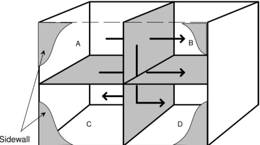
Figure 3-1: Schematic drawing of the Flanking Facility TH2 showing wall and floor specimens in grey. Arrows show some possible flanking paths.
A B
C D
Sidewall
The wall and floor specimens divide the space into four rooms (labelled A, B, C, and D in the drawing). Dimensions of the four rooms are given in the table below.
Room Volume (m3) Length (m) Width (m) Height (m) A 50.7 4.60 4.54 2.43 B 45.3 4.11 4.54 2.43 C 40.0 4.66 4.38 2.07 D 35.3 3.96 4.38 2.07
The permanent part of the facility (roof, end walls, foundation floor, and back wall) are constructed of heavy materials and are resiliently isolated from each other and from structural support members, with vibration breaks in the permanent surfaces where the specimens are installed. There is also an experimental sidewall covering the front face of the facility.
In such a facility, specific construction changes can be systematically introduced so that resulting changes in the sound insulation performance of the experimental surfaces can be accurately determined.
Using custom hardware and software developed at NRC, the measurements are performed completely under computer control, from calibration and microphone probe positioning to report generation. This provides a high degree of precision and
For conventional tests with airborne or impact sources, the sound pressure levels are sampled at a minimum of 9 positions in each room. The robot systems in each room position the microphones (12.5 mm precision condenser microphones with random incidence response), and signals are measured using a Norsonics 830 precision real-time analyser. For an airborne source, the computer directs noise signals to the loudspeakers in each room in turn to measure noise reduction between each pair of rooms and the rate of sound decay in each room. A sequence of 12 complete measurements (horizontal, vertical and diagonal pairs of rooms, each for 9
microphone positions in each room) was performed. Data presented in the report for a given room pair (e.g., A-B) are the average of two measurements, one with each room of the pair as the source. Impact measurements were made using a standard tapping machine (conforming to ASTM E1007 and ISO-140-VII) in either room A or B, and measuring the resulting sound pressure levels at all microphone positions in each of the other three rooms.
Intensity measurements were made using a B&K 3519 intensity probe fitted with 12.5 mm B&K Type 4181 precision matched condenser microphones. With a microphone separation of 12 mm, this probe was able to make measurements from 100 Hz to 5000 Hz with less than 1 dB error. The output of the probe was measured using a Norsonics 830 precision real-time analyser. Measurements were made 150 mm from the surface using the robot system in each room to position the microphones. Walls were measured at 130 locations on 10 equally spaced vertical columns. Floors were measured at 132 locations arranged on 11 equally spaced lines perpendicular to the partition wall. The distance between measurement locations increased from 150 mm for the first 600 mm from the partition wall to 400 mm so that the sampling density was highest close to the partition wall/floor junction where the structural flanking was expected to occur.
3.2 Details Of Standardised Test Methods
In this report, the performance of the system is assessed primarily using the two standard test methods referenced by the building codes.
The method of acoustic intensity is also used as it enables the measurement of the sound power of each surface and can be related to the single number ratings used by the codes.
Non-standard measures of surface velocity are used in the project to provide specific information about a path or transmission mechanism. These are discussed in the chapter where the data are presented.
The basic characteristics of the test methods are outlined below, and complete details can be found in the referenced technical standards.
3.2.1 Airborne Sound Insulation (ASTM E336 [1]):
ASTM E336 test method defines the procedure for measuring airborne sound
transmission loss for the individual one-third octave frequencies. In accordance with the standard these measures are normalised to the area of the nominally separating
Chapter 3, Measurement Methods Page 3-4
partition (wall or floor assembly). For diagonally placed rooms, which do not have a common partition the transmission loss is normalised to10 m2.
As discussed in Chapter 2, transmission loss measurements can be made without suppressed flanking to obtain a measure of the Apparent-TL, or with selected paths suppressed. In the special case that all flanking paths have been suppressed and the source and receiving rooms are separated by a common partition then the Direct-TL is measured, otherwise the Flanking-Direct-TL of one or more paths is measured. In the limit that there is no significant flanking transmission in a field construction, the Apparent-STC obtained using E336 should approximate the STC obtained under the laboratory conditions of E90 for the nominally identical floor or wall. (Appendix C provides an example).
3.2.2 Impact Sound Insulation (ASTM E1007 [2]):
The ASTM E1007 test method defines the procedure for measuring the impact sound pressure levels in a room resulting from a standardised impact source (ISO hammer box) placed on the floor in the source room. In accordance with the standard the measured impact sound pressure levels are normalised to the absorption in the receiver room. The result is the Normalised Impact Sound Pressure Level (NISPL). As discussed in Chapter 2, NISPL measurements can be made without suppressed flanking to obtain a measure of the Apparent-NISPL, or with selected paths
suppressed. In the special case that all flanking paths have been suppressed and the source and receiving rooms are separated by a common floor then the Direct-NISPL is measured, otherwise the Flanking-NSIPL of one or more paths is measured. In the limit that there is no flanking transmission, the Apparent-IIC obtained using E1007 should approximate the IIC obtained under the laboratory conditions of E492 for the identical floor. E1007 defines measurements for floor systems separating rooms one above the other. However, measurements are also reported here for horizontally adjacent and diagonally adjacent rooms.
3.2.3 Acoustic Intensity (ISO 15186-2 [3], [4]):
Intensity measurements, unlike standardised airborne and impact measures, allow for measurement of sound power radiated from each individual surface in-situ. The acoustic intensity is measured over a specific surface, usually in one-third octaves. From the data it is possible to compare the sound power radiated from each room surface in-situ. For the separating wall or floor, transmission loss data obtained from the intensity technique can be compared directly to results from the standard airborne test (E336) and can also be reduced to a single number rating.
The ASTM E2249 defines the procedure for laboratory measurements where there is suppressed flanking transmission but the field counterpart does not exist. ISO 15186 is a series consisting of three test methods. Parts 1 and 3 define laboratory
measurements and have been approved as international standards. Part 2 defines in-situ measurements. Intensity measurements made in this project followed the procedure defined in ISO 15186 Part 2.
3.3 Measures for Measurement Repeatability
Acoustical measurement in rooms involves sampling non-uniform sound fields and as such has associated with it a degree of uncertainty. By correctly performing a
number of measurements to determine a spatial average, the uncertainties can be reduced. In the case of airborne measurements, taking the mean of the two
directions can further reduce uncertainties. Of course this is not possible for impact measurements.
Basic precision limits can be described in terms of the two concepts of repeatability and reproducibility (ASTM E177 [5]).
Repeatability is defined as the closeness of agreement expected between repeated measurements of the same specimen, using the same measurement system within a short enough time to preclude specimen ageing effects. For each one-third octave band, the differences between a pair of measurements are expected to fall within the repeatability range 19 times out of 20, when making repeated measurements on a given specimen. In general, the repeatability defines the minimum possibly significant change.
Reproducibility is defined as the closeness of agreement expected between pairs of measured data obtained for the nominally identical specimen that has been constructed at different times in different laboratories. The
measurement reproducibility naturally has three components - the first is the measurement repeatability, the second is variability in the specimen or its installation due to construction practice and materials, and the third is any bias due to differences between laboratories. This would define the basic
threshold for confirming significant differences when comparing a set of test results assembled from a group of laboratories.
For this flanking study, which was performed in a single laboratory, an intermediate measure of uncertainty is required:
Rebuild Repeatability is defined as the closeness of agreement expected between pairs of measured data obtained for the nominally identical specimen that has been constructed at different times in the same laboratory. To
minimise uncertainty, the same contractor was used throughout this project and the construction materials were obtained from the same sources, namely the Steering Committee partners. For each one-third-octave-band, the differences between a pair of measurements are expected to fall within the rebuild repeatability range 19 times out of 20, when making measurements on nominally equivalent specimens.
The rebuild repeatability defines the most conservative appropriate measure to identify significant change for this study. In some of the comparisons in this study, because the construction was only slightly changed, the physical changes to the specimen are small. Hence smaller variability should be expected than would occur with complete changes of the construction. In these cases, something closer to the repeatability may be suitable to gauge if there is a significant difference. However most of the comparisons do involve appreciable reconstruction; this is obviously the
Chapter 3, Measurement Methods Page 3-6
case for changes in the type of floor joist, changes in joist direction, changes in the party wall constructions, and even when comparing the effect of successive toppings. Hence, for most cases in this project, the rebuild repeatability is a reasonable
measure to assess whether changes are significant.
Note that the magnitude of repeatability and rebuild repeatability will be different for the airborne and impact test methods. Also their magnitude should not be expected to be the same for all specimens, because the sound insulation is not equally sensitive to all construction details and not all details can be reproduced equally well. Thus, when establishing rebuild repeatability, it is important to select constructions that at least have similar dependencies.
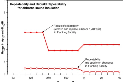
3.4 Repeatability and Rebuild Repeatability for Airborne Sound Insulation
Establishing a fully-justified estimate for the rebuild repeatability for flanking would require that a series of nominally identical specimens be constructed and measured - five specimens is proposed as the minimum set in the precision sections of ISO 140. The budget of this (and previous) flanking studies have not allowed for such a
thorough investigation of reproducibility of the results.
However, by combining the data of this study with preceding IRC/NRC laboratory studies on wall and floor specimens, it is possible to obtain a credible estimate for rebuild repeatability where a significant portion of similar specimens were removed and replaced. A small number of partial rebuilds can still provide a reasonable estimate because the changes for various room pairs can be obtained from a single rebuild.
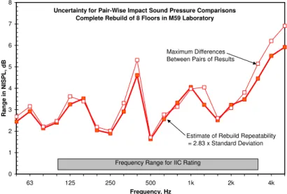
Figure 3-2: Reproducibility measures for airborne sound insulation from preceding laboratory studies of direct transmission through similar wall and floor assemblies.
Uncertainty for Pair-Wise Comparisons - Complete Rebuilds
0 1 2 3 4 5 6 7 63 125 250 500 1k 2k 4k Frequency, Hz Range in TL, dB 6 Walls in M27 Laboratory
(Rebuild Repeatability = 2.83 x Std. Dev.) 6 Walls in M27 Laboratory ( range in TL)
8 Floors in M59 Laboratory (Rebuild Repeatability = 2.83 x Std. Dev.)
8 Floors in M59 Laboratory ( range in TL)
Figure 3-2 shows the variation in airborne sound insulation results from the precision studies in the preceding laboratory investigations on 6 wall assemblies [6] and 8 floor assemblies [7]. The data provide some useful insight about estimates of the expected pair-wise differences. In each case, Figure 3-2 presents both the range of pair-wise differences observed between the pairs of results, and the values calculated from the expression 2.83 x Standard Deviation, which is expected to predict the limits of that range 19 times out of 20, according to ISO 5725 [8] and ISO 140-2 [9].