Publisher’s version / Version de l'éditeur:
MATERIALS PROCESSING AND DESIGN; Modeling, Simulation and
Applications; NUMIFORM '07; Proceedings of the 9th International Conference on
Numerical Methods in Industrial Forming Processes, pp. 787-792, 2007-05-17
READ THESE TERMS AND CONDITIONS CAREFULLY BEFORE USING THIS WEBSITE.
https://nrc-publications.canada.ca/eng/copyright
Vous avez des questions? Nous pouvons vous aider. Pour communiquer directement avec un auteur, consultez la première page de la revue dans laquelle son article a été publié afin de trouver ses coordonnées. Si vous n’arrivez pas à les repérer, communiquez avec nous à PublicationsArchive-ArchivesPublications@nrc-cnrc.gc.ca.
Questions? Contact the NRC Publications Archive team at
PublicationsArchive-ArchivesPublications@nrc-cnrc.gc.ca. If you wish to email the authors directly, please see the first page of the publication for their contact information.
NRC Publications Archive
Archives des publications du CNRC
This publication could be one of several versions: author’s original, accepted manuscript or the publisher’s version. / La version de cette publication peut être l’une des suivantes : la version prépublication de l’auteur, la version acceptée du manuscrit ou la version de l’éditeur.
For the publisher’s version, please access the DOI link below./ Pour consulter la version de l’éditeur, utilisez le lien DOI ci-dessous.
https://doi.org/10.1063/1.2740906
Access and use of this website and the material on it are subject to the Terms and Conditions set forth at
Crashworthiness of aluminium tubes; Part 1: hydroforming at different
corner-fill radii and end feeding levels
D'Amours, Guillaume; Rahem, Ahmed; Williams, Bruce; Worswick, Michael;
Mayer, Robert
https://publications-cnrc.canada.ca/fra/droits
L’accès à ce site Web et l’utilisation de son contenu sont assujettis aux conditions présentées dans le site LISEZ CES CONDITIONS ATTENTIVEMENT AVANT D’UTILISER CE SITE WEB.
NRC Publications Record / Notice d'Archives des publications de CNRC:
https://nrc-publications.canada.ca/eng/view/object/?id=3e8fe322-d1bc-4263-b382-454cef1a3e83 https://publications-cnrc.canada.ca/fra/voir/objet/?id=3e8fe322-d1bc-4263-b382-454cef1a3e83Crashworthiness of Aluminium Tubes; Part 1: Hydroforming
at Different Corner-Fill Radii and End Feeding Levels
Guillaume D'Amours
*, Ahmed Rahem
*, Bruce Williams
**, Michael Worswick
**and Robert Mayer
****National Research Council of Canada, Aluminium Technology Centre, 501 University Blvd. East, Chicoutimi, Quebec, Canada, G7H 8C3
**
University of Waterloo, 200 University Avenue West, Waterloo, Ontario, Canada, N2L 3G1
***
General Motors Technical Center, 6250 Chicago Road, Warren, MI, USA
Abstract
. The automotive industry, with an increasing demand to reduce vehicle weight through the adoption of lightweight materials, requires a search of efficient methods that suit these materials. One attractive concept is to use hydroforming of aluminium tubes. By using FE simulations, the process can be optimized to reduce the risk for failure while maintaining energy absorption and component integrity under crash conditions. It is important to capture the level of residual ductility after forming to allow proper design for crashworthiness. This paper presents numerical and experimental studies that have been carried out for high pressure hydroforming operations to study the influence of the tube corner radius, end feeding, material thinning, and work hardening in 76.2 mm diameter, 3 mm wall thickness AA5754 aluminium alloy tube. End feeding was used to increase the formability of the tubes. The influence of the end feed displacement versus tube forming pressure schedule was studied to optimize the forming process operation to reduce thinning. Validation of the numerical simulations was performed by comparison of the predicted strain distributions and thinning, with measured quantities. The effect of element formulation (thin shell versus solid elements) was also considered in the models.Keywords: Hydroforming, aluminium, end feed, finite element simulation, wall thickness reduction.
INTRODUCTION
The automotive industry is facing increasing environmental demands, including reducing fuel consumption, lowering emissions and improving recycling capabilities. Aluminium is being studied because it has low weight, good corrosion resistance, and can be recycled with much less energy than required to produce primary aluminium. On the process side, alternative design, forming and joining methods have been considered to suit this material. According to Asnafi et al. [1], the weight of the body structure can be reduced by up to 50 % by using aluminium and new forming and joining techniques, such as the hydroforming process discussed in this report. Well known automotive applications of hydroforming include subframes, engine cradles, exhaust manifolds and side members.
In a larger research project involving General Motors, the University of Waterloo, Queens University and the Aluminium Technology Centre, the interaction between tube forming operations, used to fabricate aluminium alloy structural members and their subsequent behavior during an automotive crash event have been studied. The research focuses on s-rail and axial crush structures that are designed to absorb crash
energy. Axial crush structures were considered in this report. Crashworthiness of hydroformed straight aluminium tube without end-feeding was investigated by Williams et al. [2]. In the current study, the interaction between hydroforming process with end feeding, and the crash response of AA5754 series aluminium alloy axial crush tubes, will be investigated. This paper focuses on the forming aspect of this research, with the crash response and energy absorption of the as-formed straight section tubes reported by D'Amours et al. in [3].
The geometry, thickness distribution, work hardening, and residual stresses after hydroforming, must be determined to assess crashworthiness of hydroformed aluminium alloy tubes. To ensure reliable finite element results, simulations of the crash experiments have to consider the entire forming history. Kirby et al. [4] observed a 9 % increase of the absorption energy of a hydroformed part during a crash simulation when the forming results were considered.
Numerical simulation of the hydroforming process is today well documented; however, only a few studies are presented where finite element and experimental results are compared. Hama et al. [5] investigated the hydroforming of mild steel automotive suspension components via experiments and analytical techniques.
Lang [6] has worked on the hydroforming process of aluminum tubes with different punch strokes (end feeding).
The high pressure hydroforming operation involves large straining of the tube. The hydroformed sections are generally subjected to higher expansion and the material tends to be thinner in section corner areas. End-feeding pushes material into the die, thereby increasing the formability of the tubes and reducing thinning. Nevertheless, because of the friction between the tube and the die, it is in the half length area of an axial crush tube where the maximum thickness reduction of the tube wall is still located. Thus, it was necessary to first determine an optimum pressure and end-feed profile. Optimization studies of hydroforming operations with end feeding have been published by Yang et al. [7], Abedrabbo et al. [8] and Kirby et al. [4].
To adequately simulate crash events of hydroformed tubes, it was necessary to verify that finite element solutions obtained from the hydroforming and experimental results were in good agreement. Various solvers, formulations and constitutive laws are now available in commercial FEA software. Depending on the choice of options, different finite element solutions can be obtained. Options that lead to acceptable and satisfactory finite element solutions, compared with experimental results will be identified in this paper.
Thickness changes and strain hardening are isolated in this study and compared to experimental values in order to determine their effect on crash response of straight tubes. Experiments were performed in which hydroforming process parameters were varied in a parametric fashion after which wall thicknesses and strains were measured. Experimental parameters included the hydroformed corner-fill radii of the tubes as well as consideration of different end feed levels.
NUMERICAL MODELS
Numerical Simulations
Numerical studies were carried out using LS-DYNA, version 970, with both explicit and implicit solvers. The implicit solver was used to simulate the hydroforming operation to avoid strain localizations in the corner regions when using shell elements. It is possible to use this solver because the hydroforming is a quasi static process. Kim et al. [9] and Kim et al. [10] have already used implicit solvers to simulate some hydroforming operations. Solid element models were solved using an explicit solver as no strain
localizations were observed during hydroforming simulation.
Tube and Die Geometries
Hydroforming experiments were performed on seam-welded 76.2 mm outer diameter, 3 mm thick AA5754 aluminum alloy tubes using the die system with end feed, as shown in figure 1. Three high pressure removable inserts were fabricated with three different corner-fill radii: 6, 12, and 18 mm. Finite element models of the tube hydroforming experiments were created using LS-DYNA. Due to problem symmetry and to save simulations computational time only one eighth of the die system was modeled: an eighth of the upper die half, a fourth of the plunger and an eighth of the tube.
FIGURE 1. Die with removable insert
Both the die and plunger were modeled using shell elements. For the tube, both shell and solid element type were considered. Two element sizes, 1x1 and 4x4 mm, were considered for the tube. The results presented herein are primarily those using 1x1 mm mesh. For solid element models, the same sizes were used with three elements through the wall thickness. A general surface to surface contact treatment was prescribed between the tooling and tube with a static coefficient of friction of 0.045, which was determined from twist-compression testing. Material properties corresponding to 3 mm AA5754, were assigned to the tube using a piecewise linear hardening rule with von Mises yield criterion. Material data are reported by D'Amours et al. in [11].
Pressure and End Feed Loadings
The high pressure process with end-feeding was used to form tubes with smaller corner radii. For each
of the three inserts (6, 12, and 18 mm corner radii), the internal tube pressure and two different levels of end-feed were defined. Figure 2 shows the pressure versus time profile used to produce tubes with 6, 12 and 18 mm corner radii. The same profile was used for the different inserts to allow comparison of tube thinning during hydroforming.
FIGURE 2. Pressure loadings
For end-feeding, two nominal profiles were selected: one, namely high end feed, utilized 64 mm of end-feed at each end of the tube and the other profile, which will be referred by low end feed, was selected such that there was 44 mm of end-feed. Figure 3 shows the end-feed displacement versus time profile corresponding to the low end feed. Various numerical methods have been used to identify the profile and the maximum value of the low end feed level that could be used to hydroform tube to 6 mm corner radius without burst failure.
FIGURE 3. Low end feed loading
The objective in determining an adequate end feed load curve by a numerical method, was then to minimize the thinning in the half length area. For this,
starting with initial discrete points which define the end-feed curve (figure 3), the following strategy was used:
1. Sensitivity studies were performed by using MATLAB to change automatically and successively the coordinates of each point of the last set of end-feeding curve. This creates different end feed load curves, from which the curve leading to high compressive stains and low thickness reduction at the tube half length was chosen.
2.
Optimization studies, managed by MATLAB, were carried out to fine tune the obtained curve with the aim to minimize the thickness reduction at the half length of the tube. The minimization of the mean thickness reduction of a group of tube half length elements is used as the objective function. For each new combination of discrete points defining the end feed curve, MATLAB fits the curve with a piecewise cubic Hermite interpolation and writes coordinates into a file which is read by LS-DYNA at the beginning of the hydroforming simulation.COMPARISON BETWEEN
EXPERIMENTAL AND NUMERICAL
RESULTS
Hydroforming of Aluminium Tubes
All high pressure hydroforming of AA5754 tubes with 6, 12 and 18 mm corner radii was conducted at the Aluminum Technology Centre using a 1000 ton Interlaken fully instrumented hydroforming press. The low end feed load curve, shown in figure 3 and representing the motion of each plunger, was firstly used to form the tubes to various corner-fill. The amount of end-feed for the 6 mm tubes were 44 mm. Tubes formed with the higher end feed load curve, similar to the one shown in figure 3, had 64 mm of end feed for tubes with the 6 mm corner radius. This load curve was also used to form tubes to the three corner radii with the aim of getting lower thickness reduction of the tube walls. Six different hydroformed geometries were then produced to assess the effect of tube thickness and strain hardening on their crash response. These six different deformed tubes shapes are shown in figure 4.
FIGURE 4. Hydroformed tube shapes
Experimental Measurements
Validation of finite element models through comparison with experimental results was necessary to evaluate the quality of the predicted results. For that, the following measurements were performed:
1. Thickness measurements were taken around the circumference at the half length of the tube using an ultrasonic measurement device. 2. Strain measurements were made for every
circle grid around the perimeter of the tube at the half length area using optical device. Tubes were circle-girded prior to hydroforming using electrochemical etching techniques.
In what follows, numerical and experimental results will be plotted versus angle around the tube. The weld seam corresponds at approximately 0 degree. The region of shell or solid elements for which strain and thickness results will be analyzed is located at the half length of the tube.
Observation of the Longitudinal Strains
It was anticipated that a higher level of end feed would lead to higher longitudinal strains. Figures 5 and 6 show the predicted and measured longitudinal strain distribution around the perimeter of the tube at the half length area. As expected, the higher end feed level of 64 mm led to longitudinal strains of about 50 % greater than the low end feed case, corresponding to 44 mm end feed.
FIGURE 5. Longitudinal strains for the low end feed level and insert set of 18 mm
Moreover, figure 5 shows that the finite element results for both explicit and implicit solvers are similar and are in reasonable agreement with the experimental data. Figure 6 shows that the solutions obtained with solid elements are slightly closer to the experimental results than using shell elements with implicit solver.
FIGURE 6. Longitudinal strains for the high end feed level and insert set of 6 mm
Observation of the Wall Thickness
Reductions
The distribution of the tube wall thickness reduction at its half length is dependent on both end feed level and the tube corner fillet radii. It is then the thickness variable that is interesting to observe in order to validate the finite element models. Also, this variable plays an important role concerning the absorption energy of the hydroformed tubes during a crash event. It is then necessary to predict the variation of the distribution of the tube wall thickness
reduction for the different corner fillet radii and end feed levels to assess the crashworthiness of the hydroformed tubes.
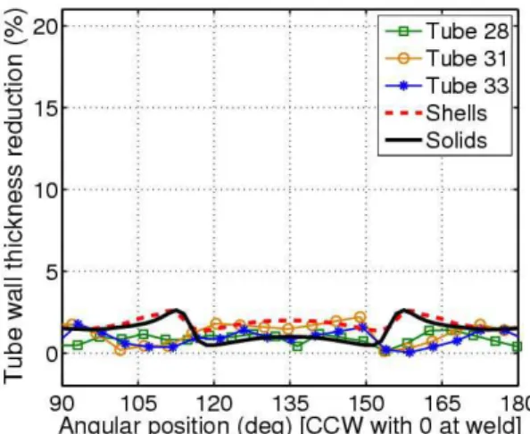
Figure 7 shows that the measured thickness reductions are small and almost negligible for the insert set of 18 mm with low end feed. Both simulation solutions predict almost the same thickness reductions which are comparable to the measured data. However, the peak thickness reductions are located at different angular locations around the tube.
FIGURE 7. Wall thickness reduction for the low end feed level and insert set of 18 mm
The results with the same 18 mm insert set but with the high end feed level are shown in figure 8. For this case, it was expected that the tube wall thickness would increase. However, as shown on figure 8, the measured thickness reductions are higher than for the low end feed. This means that the highest end feed level was too high for tubes formed to a corner fillet radius of 18 mm. The presence of light ripples or wrinkles at the surface of the tube near the ends confirmed this. The finite element model was not able to predict the appearance of these ripples at the tube ends. Similar observations have been done by Asnafi et al. [1] when large strokes are applied during tube hydroforming.
Figures 9 and 10 finally show respectively the thickness reductions of the tube wall for the insert set of 6 mm corresponding to the low and high end feed levels. The third insert set of 6 mm led to higher thickness reductions at the half length of the tubes for the low and high end feed levels. Figure 9 also shows that the finite element solutions obtained with the shell elements and the implicit solver are different from those involving solid elements and the explicit solver. The tube which received the lower end feed level during the hydroforming operation had the greatest
wall thickness reductions. Both figures show that solid element models better captured the measured thickness reductions.
FIGURE 8. Wall thickness reduction for the high end feed level and insert set of 18 mm
FIGURE 9. Wall thickness reduction for the low end
feed level and insert set of 6 mm
Simulations with shell elements were not able to correctly predict the location and the amplitude of the peaks of the thickness reductions for both end feed levels. The plane stress hypothesis used for the shell formulations could be responsible of these errors. It was seen that the error of the predicted thickness reductions was greater with shell elements when there was a greater fluid pressure near the end of the simulations. Smith et al. [12], has also shown that solid elements allow for more accurate tubular hydroforming formability assessment because the three dimensional stress states in the corner fillet regions are captured.
FIGURE 10. Wall thickness reduction for the high
end feed level and insert set of 6 mm
CONCLUSION
Aluminium tubes have been hydroformed at the Aluminium Technology Centre with different insert sets and end feed levels. The goal of the use of these three insert sets with different corner-fill radii was to allow variation of strain hardening and the distribution of the tube wall thickness reduction. Experimental measurements performed on the hydroformed tubes have shown that there is generally an increase of the wall thickness reduction when the corner-fill radius decreases. Numerical simulations performed with solid elements were able to capture the measured data.
In addition to using more than one insert set, two different end feed levels were applied to the tube ends during different hydroforming operations. In the cases of the 12 mm and 6 mm insert sets, the higher end feed level led to greater thickness reductions of the tube wall. Finite element simulations have generally under estimated the tube wall thickness reductions for the 12 and 6 mm insert sets with the shell elements when using the lower end feed level.
The solutions from the finite element simulations predicted tube wall thickness reductions reasonably similar to the experimental data. These predicted results will be transferred to crash models. The results of these crash simulations will be compared to experimental data obtained from the hydroformed tubes subjected to axial crush. The predicted and measured energy absorption characteristics will then be compared. With the developed finite element models for hydroforming and crash events, it will be possible to optimize the absorption energy of the hydroformed tubes by varying the corner fillet radii, the maximum end feed level, and the shape of the end feed load curve used.
ACKNOWLEDGMENTS
General Motors of Canada Limited, the Natural Sciences and Engineering Research Council of Canada and the National Research Council of Canada are gratefully acknowledged for supporting this work. The authors would like to express their gratitude to General Motors, the Aluminium Technology Centre and the University of Waterloo for their involvement in this project.
REFERENCES
1. N. Asnafi, T. Nilsson, and G. Lassl, Materials Science and
Engineering (2003).
2. B. Williams, D. Oliveira, C. Simha, M. Worswick, and R. Mayer, International Journal of Impact Engineering (2006), accepted for publication.
3. G. D’Amours, A. Rahem, R. Mayer, B. Williams, and M. Worswick, “Crashworthiness of aluminium tubes; Part 2 : improvement of hydroforming operation to increase absorption energy,” in Numiform 2007, edited by josé César de Sá, 2007, accepted for publication.
4. D. Kirby, S. Roy, and R. Kunju, “Optimization of tube hydroforming with consideration of manufacturing effects on structural performance,” in Numisheet 2005, edited by L. Smith, F. Pourboghrat, J. Yoon, and T. Stoughton, 2005, pp. 585–590.
5. T. Hama, M. Asakawa, and A. Makinouchi, Journal of
materials processing technology 39, 1071–1082 (2002).
6. L. Lang, S. Yuan, X. Wang, Z. Wang, Z. Fu, J. Danckert, and K. Nielsen, Journal of materials processing
technology 146, 377–388 (2004).
7. J. Yang, B. Jeon, and S. Oh, Journal of materials
processing technology 113, 666–672 (2001).
8. N. Abedrabbo, N. Zafar, R. Averill, F. Pourboghrat, and R. Sidhu, “Optimization of tube hydroforming process,” in Numiform 2004, edited by S. Ghosh, 2004.
9. J. Kim, S. Kang, and B. Kang, Computers and structures
80, 1295–1304 (2002).
10 J. Kim, Y. Kang, H. Choi, S. Hwang, and B. Kang,
International journal of advanced manufacturing technology 20, 407–413 (2002).
11. G. D’Amours, A. Rahem, R. Mayer, B. Williams, and M. Worswick, “Effects of mesh size and remapping on the predicted crash response of hydroformed tubes,” in 6th
European LS-DYNA Conference, 2007, in evaluation.
12. L. Smith, N. Ganeshmurphy, P. Murty, C. Chen, and T. Lim, Journal of materials processing technology 147, 121–130 (2004).