Publisher’s version / Version de l'éditeur:
Vous avez des questions? Nous pouvons vous aider. Pour communiquer directement avec un auteur, consultez la
première page de la revue dans laquelle son article a été publié afin de trouver ses coordonnées. Si vous n’arrivez pas à les repérer, communiquez avec nous à [email protected].
Questions? Contact the NRC Publications Archive team at
[email protected]. If you wish to email the authors directly, please see the first page of the publication for their contact information.
https://publications-cnrc.canada.ca/fra/droits
L’accès à ce site Web et l’utilisation de son contenu sont assujettis aux conditions présentées dans le site LISEZ CES CONDITIONS ATTENTIVEMENT AVANT D’UTILISER CE SITE WEB.
11th Canadian Building Science and Technology Conference [Proceedings], pp.
1-8, 2007-03-22
READ THESE TERMS AND CONDITIONS CAREFULLY BEFORE USING THIS WEBSITE.
https://nrc-publications.canada.ca/eng/copyright
NRC Publications Archive Record / Notice des Archives des publications du CNRC : https://nrc-publications.canada.ca/eng/view/object/?id=72679b7e-dbf1-4734-9b80-137312c3f5e5 https://publications-cnrc.canada.ca/fra/voir/objet/?id=72679b7e-dbf1-4734-9b80-137312c3f5e5
NRC Publications Archive
Archives des publications du CNRC
This publication could be one of several versions: author’s original, accepted manuscript or the publisher’s version. / La version de cette publication peut être l’une des suivantes : la version prépublication de l’auteur, la version acceptée du manuscrit ou la version de l’éditeur.
Access and use of this website and the material on it are subject to the Terms and Conditions set forth at
Laboratory demonstration of solar driven inward vapour diffusion in a
wall assembly
Maref, W.; Manning, M. M.; Lacasse, M. A.; Kumaran, M. K.; Cornick, S. M.;
Swinton, M. C.
http://irc.nrc-cnrc.gc.ca
L a b o r a t o r y d e m o n s t r a t i o n o f s o l a r d r i v e n
i n w a r d v a p o u r d i f f u s i o n i n a w a l l a s s e m b l y
N R C C - 4 9 2 0 3
M a r e f , W . ; M a n n i n g , M . ; L a c a s s e , M . A . ;
K u m a r a n , M . K . ; C o r n i c k , S . M . ; S w i n t o n , M . C .
A version of this document is published in / Une version de ce document se trouve dans: 11th Canadian Conference on Building Science and Technology, Banff, Alberta, March 22-23, 2007, pp. 1-8
11
thCanadian Conference on Building Science and Technology
Banff, Alberta, 2007
Laboratory Demonstration of Solar Driven Inward
Vapour Diffusion in A Wall Assembly
W. Maref1, M. Manning, M.A. Lacasse, M.K. Kumaran, S.M. Cornick and M.C. Swinton Institute for Research In Construction
National Research Council Canada
ABSTRACT: On-going discussions on various forms of moisture transport in buildings have often focused on the nature of vapour diffusion in wall assemblies. Recent field investigations at the Institute for Research in Construction (IRC), NRC Canada, have yielded data on the effect of solar radiation on the exterior surface temperature of wall assemblies. On a sunny day in August 2004, on the exterior surface of a south-facing wall, a temperature rise close to 25°C over the surrounding air temperature was recorded. Coincident increases in the absolute humidity ratio of the air in the cavity behind the brick were measured, suggesting inward drive of brick moisture into that cavity. A laboratory facility at IRC, called the Envelope Environmental Exposure Facility (EEEF) has been used to launch an investigation on the behaviour of the vapour diffusion in exterior walls exposed to solar radiation. A 2.4 m by 2.4 m test specimen of a simple wall assembly was constructed, the exterior surface of the specimen soaked in simulated rain conditions and subsequently heated by infrared heaters to mimic the rise in surface temperature due to solar radiation. The wall was fully instrumented for temperature and relative humidity measurements at both surfaces as well as at every interface. This paper presents a brief description of the EEEF, details of the test specimen and data collection, and data from the above experiment. A clear indication of an inward diffusion of water vapour across the wall as the exterior surface is heated is derived from both laboratory controlled and field experiments.
1
INTRODUCTIONSun-driven moisture is a phenomenon that occurs when walls are wetted and then heated by solar radiation. Upon solar heating, a large vapour pressure difference may occur between the exterior and the interior leading to the inward diffusion of moisture. The inward diffusion may lead to the formation of condensation on the outboard surface of the vapour retarding membrane. Inward vapour movement has also been called “Solar reversal” since the vapour movement occurs in a direction that is opposite to the direction usually considered for cold climate design (Persnail and al., 2003). Sun-driven moisture can occur when moisture is either absorbed by the exterior sheathing, or when moisture penetrates the exterior of the wall. The mechanism of inward solar drive has manifested itself in failures in the hygrothermal performance of envelopes in many ways over the years. For example, this mechanism, as an explanation for the summer condensation problem in the upper portion of basement walls was a manifestation of the same phenomenon, now being investigated in more detail for above grade wall. This phenomenon had been observed in the field, and documented and modeled for below-grade applications in the late 80’s and early 90’s in Canada (Swinton and al. 1995), and the driving factors were identified to be solar gains and warm air heating above-grade portions of the basement wall.
The same mechanisms are involved in above-grade assemblies. When the moisture is stored in the outer wall, solar heating leads to increased cladding temperatures that in turn lead to increase in vapour pressure. This inward-driven moisture usually condenses on the outboard surface of the polyethylene vapour retarder, if there is one, and runs down and accumulates at the base of the wall. Attention has to be made during the summer time when this moisture accumulates in a wall
1
11
thCanadian Conference on Building Science and Technology
Banff, Alberta, 2007
because the thermal gradient that could promote drying is relatively small during the warm season. Winter conditions can be more forgiving than summer.
Stephenson (1963) and Hutcheon (1964) discussed the effect of the solar heat on the exterior surface of buildings. Stephenson noted that the maximum temperature of the outer surface of buildings depends on its color and orientation and proximity of neighbouring surfaces; the maximum temperature for a wall surface is between 60 and 88 ºC (140 and 190 ºF).
Calculations of exterior surface temperature that have been previously reported in literature (Hutcheon, 1983) provide some indication of the substantial increases in surface temperature when exterior walls are exposed to direct solar radiation. The sun provides radiation at building surfaces at a rate that varies with time of year, time of day, orientation of the surface, clarity of the sky, surroundings and surface absorptance. This is illustrated in Figure 1, as measured in a field experiment undertaken at the Institute for Research in Construction (Ottawa, Canada) on a sunny day in August 2004. The results show that the rise in exterior surface temperature above air temperature in summer is 20 °C for a south-facing brick veneer wall at noon local time.
Figure 1 – Effect of solar radiation on the surface temperature of a south-facing brick veneer wall It can be seen that the air temperature peaks at 20 °C whereas the surface temperature of the brick peaks at close to 40 °C. Had the wall been soaked in a driving rain on the previous night, the brick would obviously have undergone drying on that sunny day. But what would have happened to the vapour that had been generated during that process? Some of it would have definitely gone to the exterior air. At the same time a vapour diffusion process towards the interior of the built environment would also have been possible as indicated by the field measurements of Saïd et al. (2003) and Wilson (1965). This would have been especially true when the brick got warmer, thereby increasing the temperature and local vapour pressure within the brick. The indoor vapour pressure at that stage would have been significantly lower than that in the brick and a “solar driven” vapour diffusion process towards the interior could not have been ruled out. If the indoor was air conditioned, say to maintain 20 °C and 50 % RH, moisture could have condensed interstitially. This phenomenon may result in harmful moisture accumulation within the wall
M a in F lo o r E n v e lo p e T ra v e rs e - S o u th W a ll 0 5 1 0 1 5 2 0 2 5 3 0 3 5 4 0 0 :0 0 2 :0 0 4 :0 0 6 :0 0 8 :0 0 1 0 :0 0 1 2 :0 0 1 4 :0 0 1 6 :0 0 1 8 :0 0 2 0 :0 0 2 2 :0 0 0 :0 0 T im e Temperature (°C) 0 1 0 0 2 0 0 3 0 0 4 0 0 5 0 0 6 0 0 7 0 0
Vertical Solar Radiation (W/m
2 )
incident on South-facing wall
E xte rio r S u rfa c e T e m p e ra tu re O u td o o r A ir T
S o la r R a d ia tio n
-11
thCanadian Conference on Building Science and Technology
Banff, Alberta, 2007
system and may lead in the long run to chemical, biological and mechanical deterioration of the wall components.
Of interest is the response of walls to North American climate variables and identifying those specific climates for which solar driven inward vapour diffusion may bring about potential problems in regard to premature deterioration of the wall assembly components. Given that a wall’s response to a specific climate is dependent on the nature and configuration of the assembly itself, verification of the response of different types of wall assemblies are of interest. As well, the significance of different interior conditions, representative of conditions currently affecting North American households, on the response of the different types of walls should also be assessed.
Accordingly, a project was initiated at the IRC to investigate the response of different types of wall assemblies to the phenomena of solar driven inward vapour diffusion. The overall objective of this project is to characterize the nature, significance and control of solar driven inward vapour diffusion in wall systems and to predict the phenomena in relation to climate and specified types of wall assemblies. The results of these studies will provide a better understanding of the nature and significance of this solar driven inward vapour diffusion, in order to develop appropriate design guidelines to predict and manage this phenomenon for various climatic conditions. The objective of a preliminary test reported in this paper is to demonstrate the effect of sun driven moisture in the laboratory using the Envelope Environmental Exposure Facility (EEEF) and try to mimic one day of an east-facing wall of a house exposed to the sun after being wet for a short period of time. This test provides a ready means of estimating the capabilities of the climatic chamber to mimic the exterior conditions for simulating the solar radiation effect on the wall response. This paper presents a brief description of the EEEF, details of the test specimen and data collection, and data from the above experiment.
2
EXPERIMENTALLaboratory tests were used to improvise climate effects of solar driven moisture evident from field measurement and thereafter this information will be used as a means to validate the results of a hygrothermal simulation model.
The test sequence was carried out in the EEEF, part of the IRC’s thermal and moisture effects laboratory. The wall is initially dry and then wetted using a spray rack integral to the EEEF and thereafter subjected to solar radiative “effects” through a set of infrared heating coils. The thermal sensors installed on each layer of the wall captured the simulated solar effects on the wall response. The criterion for solar radiative effects to occur was to heat the exterior surface until the surface temperature on the cladding (i.e. cementitious board) reached, e.g., 13 °C above the ambient temperature in the chamber.
3
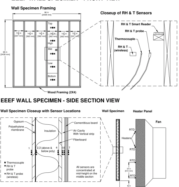
WALL CONFIGURATIONA schematic of the wall configuration is provided in Figure 2 and depicts the various components of the experimental set evaluated in this preliminary full-scale test. The experimental set consisted of evaluating the hygrothermal properties of a wood- frame wall assembly consisting of various layers of which the exterior cladding was a single sheet of cementitious board, followed by: an asphalt impregnated fiberboard sheathing, insulation placed in the cavities between the studs of the assembly, a single sheet of polyethylene installed as vapour barrier and gypsum board (dry wall) used as interior finish. The assembly was subjected to simulated rain through a series
11
thCanadian Conference on Building Science and Technology
Banff, Alberta, 2007
of water nozzles that sprayed a controlled and calibrated quantity of water onto the wall. Simulated solar radiative heating effects imparted on the cladding surface were achieved through a set of infrared heating coils located in proximity to the cladding surface. The different steps of the experiment are illustrated in Figures 10-17.
1314 in [337 mm] 1414 in [362 mm] 96 in [2438 mm] 96 in [2438 mm] Wood Framing (2X4)
EEEF WALL SPECIMEN - FRONT VIEW
RH & T (wireless)
Thermocouple RH & T probe RH & T Smart Reader
Wall Specimen Framing
Closeup of RH & T Sensors
Top High Mid Low Bottom 134 in1 [337 mm] 144 in1 [362 mm] 141 4 in [362 mm] 1414 in [362 mm] 41 2 in [114 mm] 24 in [610 mm] Heaters 24 in [610 mm] Gypsum Polyethylene
membrane Insulation Air Cavity With Vertical strip Fiberboard Cementitious board Thermocouple RH & T probe (wireless) RH & T probe 4 5 6 7 2,3 1
All sensors are concentrated at mid-height on the middle section (above & below poly) Heater Panel Wall Specimen
EEEF WALL SPECIMEN - SIDE SECTION VIEW
Wall Specimen Closeup with Sensor Locations
RTD
RTD
RTD RTD
Fan
Figure 2 – Wall specimen configuration Simulated solar radiative heating effects imparted
4
TEST PROCEDURE4.1
PREPARATION OF TEST SPECIMENThe full-scale wood frame, on which the sheathing and cladding were mounted, was placed within the opening of the precision weighing system test frame (Maref et al 2001). To cover the 2.4-m square wood-frame specimen, two (2) panels of cementitious board were used (each board 1.22-m by 2.4-m) both of which were weighed prior to being sprayed with water. The siding was sprayed over a predetermined period of time until achieving nominal moisture content of 20 %
11
thCanadian Conference on Building Science and Technology
Banff, Alberta, 2007
(wt.). This nominal moisture content was deemed sufficient for the purposes of this benchmarking exercise. A stabilisation phase was required to insure that the moisture content throughout the components reached equilibrium. During the pre-conditioning (wetting) period all measurements were monitored on a continuous basis (T, RH, MC). All panel edges were sealed to ensure that drying occurred only on the primary surfaces. The cementitious panels were mounted on the wood frame by means of screw fasteners. The edges of the wall assembly were sealed to eliminate air leakage from indoors to the outdoors.
5
PRECONDIONNING & INITIAL CONDITIONSA nominal outdoor ambient temperature of 5 °C and nominal indoor ambient temperature of 20 °C were used for the tests. The wall was subjected to rain from the spray rack for 30 minutes at 242 KPa (35 Psi), which corresponded to an average of 1.4 l/min-m2. The chamber was conditioned at nominal conditions of 5°C and 55% RH. Before starting the infrared heating, the wall was permitted to reach equilibrium with the chamber conditions for 45 minutes and then the infrared heaters were activated for 7 hours (i.e. from 10:00 AM to 5:00 PM.
6
TEST - MONITORING WALL PERFORMANCERelative humidity sensors, RTDs (Resistance Temperature Detectors) and thermocouples were used to measure relative humidity and temperatures at different levels and on each layer of the wall assembly. Each of these sensors was located at mid-section of each layer of the wall assembly (Figure 2). Readings were taken every 2 minutes and averaged every 10 minutes. The weight of each component of the wall was taken before and after the experiments, from which both the initial and final moisture contents for individual components could be determined.
7
EXPERIMENTAL RESULTSIn this paper, a select set of results is presented that illustrate the hygrothermal response of the wall assembly described above. The phenomenon of inward moisture drive is demonstrated in this straightforward test. Figure 3 shows the temperature profile of the infrared heater during the test period. From 8:50 to almost 10:00 AM the heater was turned off. During that time, the water spray is activated, and the pre-conditioning of the wall is initiated.
The water pressure to the spray nozzles was adjusted to 242 KPa (35 Psi) which provided an average deposition rate on the cladding of 1.4 l/min-m2. After 30 minutes the water spray was stopped and the wall established its initial equilibrium moisture content.
At 10:00 AM the heaters were turned on, and after 20 minutes the temperature of the heater reached 260 °C and thereafter was maintained at an average of 245 °C during 7 hours. The criterion for stopping the heater was for the surface temperature of the cladding (i.e. cementitious board) to reach 13 °C above the ambient temperature of the chamber.
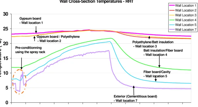
Figure 4 provides temperature profiles of the different components (layers) as a function of the test period across a section of the assembly. As is apparent from the temperature-time plots, the wall conditioning period occurs between 8:50 and 10:00 AM. During this time, the cladding surface temperature increased from 4 to 11 °C. The warming effects is due to the water spray as it was greater than that of the initial laboratory chamber temperature thus resulting in an increase in surface temperature of the cementitious board of almost 7 °C. The pre-conditioning stopped at 9:50 AM and thereafter, the surface temperature of the cementitious board decreased from 11 °C to almost 6 °C after 10 minutes given that the chamber was at 5 °C. The heaters were turned on at 10:00 AM. This effect is directly shown in the figure since there is a corresponding increase in surface temperature of the cementitious board and the temperatures of the sheathing and
11
thCanadian Conference on Building Science and Technology
Banff, Alberta, 2007
insulation. The heaters were on for almost 7 hours; over this period, the surface temperature of the cementitious board reached a maximum of 17.5 °C, i.e., 13 °C above the ambient temperature of the chamber thus ensuring that the solar effect criterion was fulfilled. The heaters were then turned off; the temperature profiles of the outer part of the wall (i.e. cementitious board, sheathing and the insulation) follow the declining temperature trend for the heater.
Figure 3- Temperature profile of the heater
Figure 4- Cross section temperature profiles versus the time of the experiment
Heater Temperature (RTD) 0 50 100 150 200 250 300 8:52 10:04 11:16 12:28 13:40 14:52 16:04 17:16 18:28 19:40 20:52 22:04 23:16 Time Temperature (°C)
Wall Cross-Section Temperatures - RHT
0 5 10 15 20 25 30 8:52 10:04 11:16 12:28 13:40 14:52 16:04 17:16 18:28 19:40 20:52 22:04 23:16 Time Temperature (°C) Wall Location 1 Wall Location 2 Wall Locaiton 3 Wall Location 4 Wall Location 5 Wall Location 7
Exterior (Cementitious board) - Wall location 7
Gypsum board - Wall location 1
Gypsum board / Polyethylene
- Wall location 2 Polyethylene/Batt insulation - Wall location 3
Batt insulation/Fiber board - Wall location 4
Fiber board/Cavity - Wall location 5 Pre-conditionning
11
thCanadian Conference on Building Science and Technology
Banff, Alberta, 2007
7.1
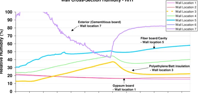
RESULTS: MASS FLOW AND THERMAL BALANCEFigure 5 shows the relative humidity profiles during the test. We can see that during the pre-conditioning phase the relative humidity near the surface of the cement board (see Figure 4; Location 7) is 100 % and above and stayed until 11:30 AM. This was due to the water spray that saturates the sensors and the surface of the cement board is saturated as well. After that period, the heater had an effect on the surface.
This is similar to rain deposition on the wall, which is in part driven inward in the form of water vapour when the sun’s radiation heats the surface of the moisture-laden cladding. (Surface evaporation would also take place in this drying process, but this component was not measured). It is quite evident in this graph that the surface relative humidity of the cement decreases whilst the relative humidity of the cavity increases as does the relative humidity of the insulation both sides (sheathing and the poly). The relative humidity of the cavity started at 30% and reached 52 % during the heating period. This graph shows the inward moisture drive brought about by the simulated radiative effects of the sun. Figure 6 shows the humidity ratio profiles of each component of the wall during the test.
Figure 5- Cross section relative humidity profiles versus the time of the experiment Wall Cross-Section Humidity - RHT
0 10 20 30 40 50 60 70 80 90 100 8:52 10:04 11:16 12:28 13:40 14:52 16:04 17:16 18:28 19:40 20:52 22:04 23:16 Date and Time
Relative Humidity (%) Wall Location 1 Wall Location 2 Wall Locaiton 3 Wall Location 4 Wall Location 5 Wall Location 6 Wall Location 7 Polyethylene/Batt insulation - Wall location 3
Exterior (Cementitious board) - Wall location 7
Gypsum board - Wall location 1
Fiber board/Cavity - Wall location 5
11
thCanadian Conference on Building Science and Technology
Banff, Alberta, 2007
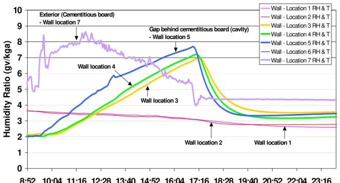
Figure 6- Cross section humidity ratio
Figure 7- Wall cavity behind cement humidity ratio –Lab experiment
The humidity ratio of the outside air (i.e. chamber temperature) and the cavity behind the cement board are represented in Figure 7. It shows that the heater is on from 10:00 AM until 5:00 PM.
Wall Cross-Section Humidity - RHT
0 1 2 3 4 5 6 7 8 9 10 8:52 10:04 11:16 12:28 13:40 14:52 16:04 17:16 18:28 19:40 20:52 22:04 23:16 Time
Humidity Ratio (gv/kga)
Wall - Location 1 RH & T Wall - Location 2 RH & T Wall - Location 3 RH & T Wall - Location 4 RH & T Wall - Location 5 RH & T Wall - Location 6 RH & T Wall - Location 7 RH & T Gap behind cementitious board (cavity)
- Wall location 5 Exterior (Cementitious board)
- Wall location 7
Wall location 4
Wall location 3
Wall location 2 Wall location 1
Wall Cross-Section Humidity - RHT
0 1 2 3 4 5 6 7 8 9 10 8:52 10:04 11:16 12:28 13:40 14:52 16:04 17:16 18:28 19:40 20:52 22:04 23:16 Time
Humidity Ratio (gv/kga)
Wall - Location 1
Gap behind cementitious board (cavity) - Wall location 5
Chamber humidity - Simulating outside Humidity- Wall location 6
11
thCanadian Conference on Building Science and Technology
Banff, Alberta, 2007
The moisture is driven into the cavity when the heater is on; this simulates for example an east-facing wall of a house exposed to the sun. The humidity ratio at 10:00 AM starts at 2 gv/kg reaching 7.5-gv/kg air at 5:00 PM. Thereafter, with no infrared heating, there is necessarily a reduction in humidity ratio, simulating, at this stage, a night sky radiation effect (4.5 gv/kg air). The inward moisture drive shown on this graph occurs between 1:00 PM and 5:00 PM, with the humidity ratio in the cavity being above that of the outside ratio.
There is a good similarity between this laboratory experiment and a field test conducted at the Canadian Center for Housing Technology (CCHT) (see Figure 8). Figure 9 provides a plot of the humidity ratio over a period of a day (24 August) for an East-facing brick veneer wall of the CCHT test facility. Humidity profiles are taken for the outside surface of the wall and in the space behind the brick veneer cladding at the second floor level. It can be seen that the sun does not shine directly on the east wall for a long period of time (i.e. humidity ratio declines from 0 to ca. 7:15 AM).
Figure 8- Canadian Center for Housing Technology
Figure 9- East wall gap behind brick humidity ratio at CCHT
The moisture is driven into the cavity when the sun heats the East wall from about 8:00 AM to 1:00 PM. The humidity ratio starts at 4.5 and reaches 7 gv/kg air at 10:00 AM and then back to no
C C HT - 2nd Floor East W all G ap Behind B rick Hum idity R atio
0 1 2 3 4 5 6 7 8 9 10 0:00 2:00 4:00 6:00 8:00 10:00 12:00 14:00 16:00 18:00 20:00 22:00 0:00 Tim e
Humidity Ratio (gv/kg air
)
G ap behind brick H um idity O utside H um idity
24-Aug-11
thCanadian Conference on Building Science and Technology
Banff, Alberta, 2007
solar radiation effect (4.5 gv/kg air). The inward moisture drive is shown on this graph between 9:00 AM and 12:00 PM, given that the ratio in the cavity is above the ratio given at the outside of the wall.
8
CONCLUDING REMARKSField monitoring of the wall envelope system yielded valuable insights on order of magnitude of inward moisture transfer for the particular cases investigated. Nevertheless, the fieldwork is limited by the difficulty in retrofitting an entire array of sensors in a wall that has been already built. As well, the field monitoring offers no control over climate parameters. The latter is especially important in the investigation of inward vapour drive, which requires a specific set of circumstances for the phenomenon to occur: typically a wind-driven rain event followed by sunshine. Such events become quite scarce and difficult to capture once directionality is imposed: the events need to occur on the same wall and direction in the right sequence.
The investigation is therefore best served by combining field data and lab tests, using the former to benchmark the lab ‘simulation’ of weather events and wall response. In this way, selected weather events can be simulated by capturing key weather patterns from the field and then reproduced to assist in parameter investigations. This paper has illustrated how this process can be made to work, with some degree of success.
The examples provided in this paper, though not involving the same assemblies (brick veneer in the field vs. unfinished fibre-cement cladding in the lab) and not directly comparable, nonetheless illustrate the order of magnitude and duration of heat driven inward vapour drive of two different assemblies. Figure 7, which is laboratory test, and Figure 9, which is field test, showed us that we could mimic in the lab similar orders of magnitude of changes in terms of absolute humidity ratios in envelope cavities during the phenomenon of inward vapour drive.
The preliminary test conducted at the Institute for Research in Construction demonstrated the capabilities of IRC’s facilities to carry out a series of laboratory and field experiments to mimic solar radiation effects on moisture transport, and capture the key parameters involved in characterizing the phenomenon of inward vapour drive. Future investigations should look at improving the lab simulation of weather parameters as well as investigating the conditions and constructions that might lead to prolonged and elevated relative humidity inside the wood cavity, and strategies to defeat the phenomenon in both field and laboratory experiments and modeling.
10. ACKNOWLEDGMENTS
The authors would like to thank Mr. D. Booth and Mr. D. Van Reenen for having helped Ms. Manning write the data acquisition program and install new electrical equipment to the EEEF. Our gratitude is likewise extended to Mr. M. Nicholls and Mr. Ken Trischuk for having fabricated and assembled the apparatus and helped set-up the experiments.
11. REFERENCES
Persnail, K., Timusk, J., Kan, L., Dong, B., Kan, V., “In Search of a Wall for All Seasons: Controlling Sun-Driven Moisture”, 9th Canadian Conference on Building Science and Technology (Vancouver, BC, Canada), pp. 157-170, Feb. 27 & 28, 2003.
Swinton, M.C., Karagiozis, A.N., "Investigation of warm weather condensation in new and insulated basement walls," Thermal Performance of the Exterior Envelopes of Buildings VI (Clearwater, Florida, USA, December 05, 1995), pp. 101-107, December 01, 1995 (NRCC-38754) (IRC-P-4035)
11
thCanadian Conference on Building Science and Technology
Banff, Alberta, 2007
Stephenson, D., Extreme Temperatures at the Outer Surfaces of Buildings, Institute for Research in Construction, Canadian Building Digest, CBD-47, November 1963.
Hutcheon, N.B., Principles Applied to an Insulated Masonry Wall, Institute for Research in Construction, Canadian Building Digest, CBD-50, February 1964.
Hutcheon N.B. and G.O.P. Handegord, “Building for a cold climate”, John Wiley & Son, Canada 1983, p. 228.
Said, M.N.; Demers, R.G.; McSheffrey, L.L., "Hygrothermal performance of a masonry wall retrofitted with interior insulation", Proceedings of the 2nd International Conference on Building Physics, Sept. 14-18, 2003, Leuven, Belgium, pp. 445-454(NRCC-46109)
.http://irc.nrc-cnrc.gc.ca/fulltext/nrcc46109/
Wilson, A.G. Condensation in insulated masonry walls in summer. RILEM/CIB Symposium Moisture Problems in Buildings, Helsinki, Finland, August 16-19,1965
Maref, W.; Lacasse, M.A.; Krouglicof, N. "A Precision weighing system for helping assess the hygrothermal response of full-scale wall assemblies," Performance of Exterior Envelopes of Whole Building VIII: Integration of Building Envelopes (Clearwater Beach, FL, 12/2/2001), pp. 1-7, December 12, 2001 (NRCC-45202)
Figure 10- Installation of the wood-stud frame
11
thCanadian Conference on Building Science and Technology
Banff, Alberta, 2007
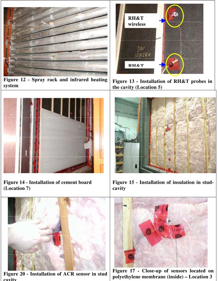
Figure 12 - Spray rack and infrared heating
system Figure 13 - Installation of RH&T probes in the cavity (Location 5)
Figure 14 - Installation of cement board (Location 7)
Figure 15 - Installation of insulation in stud-cavity
Figure 20 - Installation of ACR sensor in stud cavity
Figure 17 - Close-up of sensors located on polyethylene membrane (inside) – Location 3
RH&T wireless