Publisher’s version / Version de l'éditeur:
Insight - Non-Destructive Testing and Condition Monitoring, 47, 4, pp. 216-219,
2005-04-01
READ THESE TERMS AND CONDITIONS CAREFULLY BEFORE USING THIS WEBSITE.
https://nrc-publications.canada.ca/eng/copyright
Vous avez des questions? Nous pouvons vous aider. Pour communiquer directement avec un auteur, consultez la
première page de la revue dans laquelle son article a été publié afin de trouver ses coordonnées. Si vous n’arrivez pas à les repérer, communiquez avec nous à [email protected].
Questions? Contact the NRC Publications Archive team at
[email protected]. If you wish to email the authors directly, please see the first page of the publication for their contact information.
NRC Publications Archive
Archives des publications du CNRC
This publication could be one of several versions: author’s original, accepted manuscript or the publisher’s version. / La version de cette publication peut être l’une des suivantes : la version prépublication de l’auteur, la version acceptée du manuscrit ou la version de l’éditeur.
For the publisher’s version, please access the DOI link below./ Pour consulter la version de l’éditeur, utilisez le lien DOI ci-dessous.
https://doi.org/10.1784/insi.47.4.216.63149
Access and use of this website and the material on it are subject to the Terms and Conditions set forth at
Low-coherence interferometry – an advanced technique for optical
metrology in industry
Dufour, M. L; Lamouche, G.; Detalle, V.; Gauthier, B.; Sammut, P.
https://publications-cnrc.canada.ca/fra/droits
L’accès à ce site Web et l’utilisation de son contenu sont assujettis aux conditions présentées dans le site LISEZ CES CONDITIONS ATTENTIVEMENT AVANT D’UTILISER CE SITE WEB.
NRC Publications Record / Notice d'Archives des publications de CNRC:
https://nrc-publications.canada.ca/eng/view/object/?id=639dcb2c-e3d6-4d7a-84ae-81911216eb80
https://publications-cnrc.canada.ca/fra/voir/objet/?id=639dcb2c-e3d6-4d7a-84ae-81911216eb80
Introduction
Low-Coherence Interferometry (LCI) is an optical technique that relies on ‘coherence gating’ to provide precise axial positioning of an object in the direction of light propagation. By focusing the light in a sample, one also obtains a good transverse resolution (perpendicular to the optical beam), thus collecting information from a inite volume for imaging or optical characterisation purposes. This application has evolved at a fast pace in the last decade, especially for the characterisation of biological tissues under the ield of Optical Coherence Tomography (OCT). Signiicant achievements were reported both for the underlying technology (optical sources, scanning systems) and the diagnostic capabilities. Successful applications of OCT have been reported in various medical ields like ophthalmology, dermatology and cardiology.(1) LCI is also full of promises for industrial applications,
a ield that is not yet fully exploited. One of the few examples found in the literature is the measurement of the level of molten glass with a temperature over the surface in the range of 800°C.(2)
An LCI system can provide precision of the order of microns, both in the axial and transverse positions. A fibre-based system where the light is brought to the sample through a single-mode fibre allows isolating the measurement location from the system main components at a distance of metres or even hundreds of metres. There is no direct contact between the sample and the fibre output, thus allowing measurements on samples at high temperature. A system can thus be easily adapted to industrial conditions even in a harsh environment and tight location. A small optical head can
be brought close to the sample for illumination purpose while the sensitive electronics is kept away in a more suitable environment.
In this paper, industrial applications of LCI recently developed at the Industrial Materials Institute (IMI) are reviewed. Firstly, LCI is used to monitor the thickness and width of polymer sample being stretched in an elongational rheometer. Secondly, LCI provides information about the volume loss in a wear test. Thirdly, LCI is combined with laser-induced breakdown spectroscopy (LIBS) to provide chemical information as a function of depth in a material. These applications pertain to different industrial fields and should give an appreciation of the large potential of LCI to address industrial challenges.
Principles of LCI
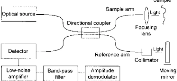
The optical coniguration of a typical LCI system based on ibre optics is illustrated in Figure 1. A single 2x2 optical ibre coupler is used to implement a Michelson interferometer. The power of a low-coherence source, typically a superluminescent diode, is divided into the sample arm and the reference arm of the interferometer through the ibre coupler. The light relected by the relectors in the sample is recollected by the sample arm ibre. The light relected by the reference mirror is recollected by the reference arm ibre. The light from both the sample and reference arms is again coupled back in the ibre coupler and part of it is redirected towards the detector. Due to the inite coherence length of the source, optical interference is observed only when the optical pathlengths of the beams relected by the sample relector and the reference mirror differ from less than the coherence length.
During a measurement, the reference mirror is scanned. Figure 2 presents a typical signal recorded on the detector for a single reflector in the sample arm as a function of the optical path difference. The signal is composed of a continuous background on which is superimposed an oscillatory pattern resulting from successive constructive and destructive interferences. The interference pattern is modulated by an envelope function related to the coherence function of the source. It is a common practice to consider only the envelope function and, using a well-calibrated system, the position of a reflector in the sample arm is determined by the centre of the envelope function. For a source with a gaussian
INTERFEROMETRY
Low-coherence interferometry – an advanced technique
for optical metrology in industry
M L Dufour, G Lamouche, V Detalle, B Gauthier and P Sammut
Based on a paper presented to the 16th World Conference on NDT, Montréal, Canada, August-September 2004.
Low-coherence interferometry (LCI) is an optical technique
that may be used for industrial surface metrology with
accuracy in the micron range. An instrument made with
optical ibres is rugged enough to be used in industrial
environments and the ibre-linked optical probe may be
miniaturised for accessing tight locations. Among industrial
applications developed at IMI, several cases for which
LCI has been particularly useful, such as an elongational
rheometer (RME), characterisation of wear damages on
coating and laser-induced breakdown spectroscopy (LIBS),
will be presented. The RME is an instrument in which a
polymer sample is stretched in a controlled temperature
furnace at up to 350°C. LCI has been used for monitoring
the thickness of the samples. Wear damage is quantiied by
the volume loss after a wear test. It requires a high depth
resolution (axis perpendicular to the surface) but a relatively
coarse transverse resolution. The LIBS is a technique that
has been used for analysing the chemical composition of
materials as a function of depth. LCI has been integrated to
a LIBS instrument for measuring accurately the crater depth
between each laser shot.
M L Dufour, G Lamouche, V Detalle, B Gauthier and P Sammutare with
the Industrial Materials Institute, National Research Council, Boucherville, Quebec, Canada.
Figure 1. Typical coniguration of a ibre-based system for low coherence interferometry
Insight Vol 47 No 4 April 2005 217
spectrum centred on wavelength l0 with a spectral width Dl,
the resolution provided by the envelope function is Dz = 2ln(2)l2 / (pDl).(1) A superluminescent diode provides a
typical resolution of a few tens of microns. In the case of a sample containing well-spaced reflectors, a defined envelope function is recorded for each reflector. The position of the reflector can be determined more precisely by locating the exact position of the maximum of the envelope function, providing submicron resolution. This is often encountered in industrial applications.
The above discussion focuses on the axial resolution provided through what is called ‘coherence gating’ in low coherence interferometry. The transverse resolution (perpendicular to the optical axis) is provided by the focusing optics in the sample arm. It is a common practice to rely on high quality optical components to work with diffraction limited spot sizes. The exact choice of components is application specific, being a trade-off between spot size and depth of focus.
Elongational rheometry
The relevance of elongational low properties of polymers to industrial processes such as ilm blowing and foam extrusion is now well recognised. The rotary clamp elongational rheometer, built around a counter-rotating belts principle use to stretch a polymeric material in the molten state, enables precise determination of the low properties under controlled experimental conditions. The underlying experimental concept is based on the constant gauge length method where a specimen is subjected to an uniaxial deformation under a constant strain rate.(3) In short, this constant
gauge length rheometer draws the specimen at ixed points in space, maintaining the specimen length constant but changing its volume. The challenge is to accurately monitor, in real time, the volume change. This kind of measurement is very delicate, especially since very high strains can be achieved (more than 1000 times the initial length), and the material deformation must be carefully monitored to evaluate the true strain rate. The strain rate can be inferred by imaging the sample shape or a pattern at the surface of the sample. This is nevertheless a tedious and non-eficient approach.(4)
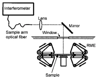
LCI is very well suited for this task since polymeric materials are translucent to visible and near-infrared light. LCI is non-contact and can easily be applied to a sample heated at a few hundred degrees Celsius as in the case of a Polymer Melt Elongational Rheometer for Melts (RME). The experimental set-up is illustrated in Figure 3, in which the sample is stretched using rotary belts in the RME apparatus. The output of the sample arm fibre is focused in the sample region. A rotating mirror is used to scan the sample along its width. The front and rear faces of the polymer film provide two peaks in the LCI measurement from which the optical thickness
Topt between the two polymer faces is evaluated. It is related to the
true geometrical thickness T and the film refractive index n by
Topt = nT. If the refractive index is unknown, the true thickness can
still be obtained by measuring the position of a backward reference surface with and without the film, the difference in optical distance being given by DD = (n – 1)T. It is then quite straightforward to obtain the true thickness of the film T = Topt – DD and its refractive
index n = Topt / T. The width of the film is obtained by displacing
the spot from one side of the sample to the other with the rotating mirror, locating the extrema positions at which the reflections from the polymer film disappear.
LCI can thus provide accurate real-time measurements of the geometrical deformation of the film. This information can then be used to evaluate precisely the true strain rate applied to the film and improve the accuracy of the measurements performed with the elongational rheometer. Figure 4 presents the comparison between the true strain rates in an RME measurement evaluated with the LCI approach (lines) and with a more conventional video imaging technique. A LCI system is now permanently installed and used on the RME device at IMI.
Wear test
The accuracy provided by LCI measurements makes it an ideal candidate for proilometry. When the sample presents a well-deined interface, a resolution of the order of a micron can be obtained even with a superluminescent source with a coherence length in the tens of microns since the centre of the envelope function can
Figure 2. Interference signal recorded from a single relector as a function of the optical pathlength difference
Figure 3. Experimental set-up for LCI characterisation of the sample deformation in a Rheometric Elongational Rheometer for Melts (RME)
Figure 4. Comparison between the true strain rates evaluated using LCI (lines) and using a more conventional technique using video imaging (open symbols). The strain rates are evaluated from the variation (x0 /xI) of the thickness (LCI) or
width (video imaging) of the sample with time
Insight Vol 47 No 4 April 2005 217
be precisely determined. One such application developed at IMI is volume loss determination in a wear test. A surface map is obtained by scanning LCI measurements over the damaged region. The scanned surface must exceed the damaged region since an intact surface around it is necessary for reference purpose. The volume loss is evaluated by irst determining the reference proile corresponding to an intact region. Then, each point measured on the damaged surface is compared to this reference surface and the measured differences are summed.
Typically, a surface of 10 mm x 10 mm must be scanned for erosion tests, while 20 mm x 50 mm are required for an abrasion test with a rubber wheel. The required transverse resolution is not too severe, being about 100 microns x 100 microns. However, the resolution in depth (axial resolution) must be of the order of a micron, since the maximum depth measured in a wear test is of the order of 10 microns. Figure 5 presents the results of a LCI characterisation of an erosion test. A maximal depth of 8 microns was measured and the total volume loss was evaluated to 0.03 mm2.
IMI developed a robust and low-cost prototype for this application. Its first client was its Surface Technologies group which has successfully used the system for more than four years. A system was also delivered to Syncrude Canada Ltd.
Laser-induced breakdown spectroscopy
The laser-induced breakdown spectroscopy (LIBS) is a powerful technique for rapid on-site analysis of solid, liquid, or gas. A powerful laser beam is focused on a sample, some matter is vaporised and a hot spark (plasma) is formed. Light emitted by the plasma is composed of spectral lines characteristic of the elements present in the sample. By spectrally analysing this light, it is possible to deduce the elemental composition of the material under study. Moreover, the proportionality of spectral line intensity to elemental concentration enables quantitative analysis. The detection limit of the technique is in the ppb range.In a solid, the concentration of an element can be traced as a function of the depth in the material by continuously firing the laser at the same spot. The depth can be estimated by first calibrating the amount of volume vaporised for each pulse. However, this is a tedious process that asks for different calibration curves for different materials and different operating conditions.
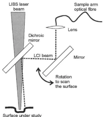
LCI is very well suited to complement the LIBS apparatus to provide depth information. A typical LIBS crater is 1 mm in diameter and the LCI beam can easily reach the bottom of the crater to provide depth information. Figure 6 illustrates the combination of a LCI system with a LIBS system. Only the illumination part of the sample is shown. The LIBS system operates with a laser beam at 1.06 microns focused on the sample surface. The LCI system operates around 1.3 microns, thus the output of the sample arm
fibre can be combined with the LIBS beam with a dichroic mirror. Prior to the dichroic mirror, the LCI beam is deflected by a rotating mirror that allows scanning of the LIBS crater along a line. It is more efficient to observe also the surroundings of the crater to obtain a more accurate estimate of the crater depth. Typically, for a crater of 1 mm diameter, the LCI measurement is performed along a 3 mm line.
Figure 7 shows the measured depth as a function of the number of laser pulses in a steel sheet with a zinc coating. It takes about 140 pulses to dig through the zinc layer for which the removal rate
Figure 5. Proilometry of a surface after a wear test as measured by LCI
Figure 6. Illumination of the sample for simultaneous LIBS and LCI measurements
Figure 7. Depth as a function of the number of laser pulses as measured by LCI for steel sample coated with zinc
Figure 8. LIBS concentration of zinc as a function of depth for a steel sample coated with zinc. Different spot sizes for LIBS measurements are compared. In both case, the depth is measured with LCI
Insight Vol 47 No 4 April 2005 219
is about 55 nm/pulse. In steel, the removal rate is much lower and is about 7 nm/pulse. Figure 8 shows the concentration of zinc as a function of depth for a steel sample coated with zinc. The results of two LIBS configurations are shown (different ablation spots), and in both case, LCI is used to measure the depth. This can be used to measure the thickness of the zinc layer. This demonstrates the ability of the LCI system to complement the LIBS apparatus in providing depth information.
Conclusion
Some applications of LCI for industrial applications developed at IMI over the recent years are reviewed in this paper. LCI is a non-destructive and non-contact technique. It can thus be applied on high temperature samples. It is highly adaptable to various industrial conditions since only the optics of the sample arm output needs to be close to the sample. The other components of the interferometer can be put at distances as high as hundreds of meters if one uses a ibre-based delivery. In vivo imaging of the interior walls of an artery have been demonstrated in biomedical
applications. Industrial applications of LCI in tight locations should thus be easily achieved. The LCI technique is versatile enough to be coupled with another technique to improve the precision of the latter or enlarge its functionality. It is a technique that is full of potential for a variety of industrial applications and more of these applications should become evident over the forthcoming years.
References
1. B E Bouma and G J Tearney, eds, Handbook of Optical
Coherence Tomography (Marcel Dekker, New York, 2002).
2. L Giniunas, R Karkockas, and R Danielius, ‘Accurate remote distance sensing by use of low-coherence interferometry: an industrial application,’ Applied Optics 37(28), 6729-6733 (1998).
3. T Schweizer, ‘The uniaxial elongational rheometer RME - six years of experience,’ Rheologica Acta 39(5), 428-443 (2000). 4. R Gendron, P Sammut, M Dufour, and B Gauthier,
‘Low-coherence interferometry applied to uniaxial elongational rheometry,’ presented at the Annual Technical Conference ANTEC, Conference Proceedings, 2003.