HAL Id: hal-02869726
https://hal.archives-ouvertes.fr/hal-02869726
Submitted on 20 Nov 2020
HAL is a multi-disciplinary open access
archive for the deposit and dissemination of
sci-entific research documents, whether they are
pub-lished or not. The documents may come from
teaching and research institutions in France or
abroad, or from public or private research centers.
L’archive ouverte pluridisciplinaire HAL, est
destinée au dépôt et à la diffusion de documents
scientifiques de niveau recherche, publiés ou non,
émanant des établissements d’enseignement et de
recherche français ou étrangers, des laboratoires
publics ou privés.
Recent advances in the electrooxidation of
biomass-based organic molecules for energy, chemicals
and hydrogen production
Yaovi Holade, Nazym Tuleushova, Sophie Tingry, Karine Servat, Teko
Napporn, Hazar Guesmi, David Cornu, K. Boniface Kokoh
To cite this version:
Yaovi Holade, Nazym Tuleushova, Sophie Tingry, Karine Servat, Teko Napporn, et al.. Recent
ad-vances in the electrooxidation of biomass-based organic molecules for energy, chemicals and hydrogen
production. Catalysis Science & Technology, Royal Society of Chemistry, 2020, 10 (10), pp.3071-3112.
�10.1039/C9CY02446H�. �hal-02869726�
Recent advances in the electrooxidation of biomass-based organic
molecules for energy, chemicals and hydrogen production
Yaovi Holade,a* Nazym Tuleushova,a Sophie Tingry,a Karine Servat,b Teko W. Napporn,b Hazar
Guesmi,c David Cornu,a and K. Boniface Kokohb*
Electrosynthesis, a historically powerful tool for the production of a number of industrial-scale inorganic or organic materials, has experienced a renaissance over the last ten years with research efforts seeking a dual production platform for molecules and energy carriers. It is termed a “Power-to-X” approach. Specifically, hydrogen (H2) is a key compound in emerging energy conversion and storage systems, acting as an energy carrier to provide electrical energy with a significantly reduced environmental footprint through H2/O2 fuel cells. The clean energy production strategy from energy carrier is inversely termed an “X-to-Power” approach. However, H2 source remains up to now the main key challenge. An increasing interest surrounds the development of advanced low energy consumption electrolysis cells enabling reliable, sustainable and dual production of both H2 and valuable chemicals from the selective oxidation of surplus biomass-derivates. It can thus be summed up that the tremendous idea of generating electricity or producing fuels such as H2, while synthesizing chemicals is an attractive pathway for organic synthesis and electricity production. However, precisely how this could be achieved in a cheap and sustainable way remains a puzzle for scientists. However, the organics selective electrooxidation reactions are central topics and bridge fuel cells and electrolysis cells research. A number of (bio)catalytic interfaces have been developed to overcome their sluggish electrochemical kinetics. Within this Perspective, we propose a detailed review on the recent advances over the last ten years in co-generative fuel cells and electrolysis cells that operate with biomass-based organic molecules (ethanol, ethylene glycol, glycerol, (oligo)saccharides, cellulose, hemicellulose) while highlighting experimental and theoretical research that unifies those fields to yield devices with improved performance. The identified main electrocatalytic reaction descriptors allow for new materials to be proposed, which could enable maximized activity, selectivity and durability of anode materials. This perspective particularly enlightens the missing fundamental knowledge on parameters dictating electrocatalysis of organic compounds in aqueous media. Overall, we discuss the implications for the wider scientific community of electrochemistry, electrocatalysis, materials science and organic chemistry, and finally provide several logical pathways and guidelines to stimulate progress, inspiring the development of organic-fuelled cogeneration electrochemical devices.
1. Introduction
In the mid-1990s, global electrical energy conversion systems have undergone a significant metamorphosis due to either a decline in fossil energy resources or environmental issues.1,2
Advances in technology have opened opportunities to reduce pollution due to greenhouse gases or fine particles resulting from internal combustion engines by designing relatively sustainable systems. Part of the proposed systems that are solar, wind and hydro based devices is intermittent and dependent on climatic conditions. Moreover, they cannot fairly satisfy the need for off-grid energy. A remaining option is electrochemical energy conversion and storage3 referred to as
batteries.4,5 Fuel cells that have the primarily role of converting
chemical energy stored as chemical bonds in molecules into electricity is expected to play a central role in delivering clean electrical energy in the next decades. Specifically, H2-based fuel
cells are considered to be the most promising sustainable solution to reduce our dependence on conventional fossil fuel energy sources. H2/O2 fuel cells that can be broadly defined as
a H2 combustion reaction (2H2 + O2 → 2H2O + heat) have been
extensively investigated as a major alternative source of electrical energy production.6-8 The overall operating reaction
indicates that the only formed product is H2O. It thus enables
the production of electricity with a significantly reduced environmental footprint during operation. So, in addition to the traditional end-use of H2 such as Haber-Bosch process of
ammonia synthesis, Fischer-Tropsch process for hydrocarbons
synthesis and metal refining among others, it has been now accepted as a fait accompli that this simple molecule is a cornerstone in the energy transition era, acting as an energy carrier in H2/O2 fuel cells. However, a sustainable production of
H2 remains up to now the main key challenge.
In the early 2000s, some organic molecules were extensively scrutinized as alternative fuels to H2 fuel cells, owing to their
attractive easy-to-produce, easy-to-handle and easy-to-use characteristics.9 Relatively small organic molecules such as
ethanol and glycerol have been particularly studied in half-cell and single-cell electrochemical setups as potential fuels because of their low toxicity/volatility, and transport/storage facilities.10-29 It is worth mentioning that the most common
oligosaccharides (glucose, fructose, cellobiose, lactose) have been extensively investigated to serve as potential fuels for a type of fuel cells, so-called biofuel cells, to power micro-power electronic or implantable devices.30-33 When using a
carbon-based fuel in fuel cells, the best scenario for environment issue should not be the complete oxidation of the fuel to CO2, but
rather a tight control of selectivity towards production of valuable chemical(s). Glycerol and oligosaccharides may be extremely interesting since their selective oxidation leads to valuable products owing to their hydroxyl groups.12,24,25,34-36
Hence, the envisaged idea of generating electricity while synthesizing platform chemicals (cogeneration strategy), can subtly become a reality. A crucial parameter for such systems is their performance in terms of the electrical power delivery. The maximum power density (Pmax) for low temperature fuel cells
environments or an anion exchange membrane (AEM) for alkaline media is about 0.5-2 W cm−2 for the state-of-the-art
H2/O2 fuel cell, whereas those based on organic molecules can
barely deliver 0.2 W cm−2.12,37-43 This means that instead of using
organic molecules directly in fuel cells, they act as an indirect route for a cheap H2 production.
Currently, H2 production is mainly (96%) based on the
thermal decomposition of fossil fuels, leading to CO2 and CO
emissions and excessive energy consumption.44,45 This strategy
seemingly violates the original intention of reducing global warming by the employment of H2 fuel cells.45 Therefore, a
clean, renewable and efficient strategy for H2 production is
highly sought after. Responsible for the remaining 4% of H2
production, water electrolysis faces major scientific and economic constraints due to the use of precious and/or rare metals (Pt, Ru, Ir) and high energy consumption (5 kWh/(Nm3H2) at 10 kA m-2).12,46 Indeed, the deployment of
low-temperature water electrolysis as CO2-free Power-to-X (X = fuel,
chemical) scenarios to make clean H2 has been impeded by the
aforementioned issues. Specifically, the large overpotential of the oxygen evolution reaction (OER) at the anode is an issue. Furthermore, making electrolysis a reliable alternative relies on the development of robust, inexpensive and high-performance catalysts for the positive electrode. In addition to its production route, the future of H2 depends on advances in the areas of
infrastructure, distribution, on-board fuel tank and on-board end-use.47 To address the electrochemical H2 production issues
and as an alternative to water splitting, a change in paradigm has been envisaged with the production of H2 from organic
molecules.
Electrolysis cells, commonly known as “electrolysers” are electricity driven electrochemical devices that utilize electrode materials and electrical current as the sole inputs to perform chemical oxidation or reduction reactions and have led to breakthroughs in organic electrosynthesis (minimizing hazardous reagents, avoiding large quantities of stoichiometric oxidizers and reductive reagents), mainly in unexplored classes of natural products for which organic synthesis has no practical solution.48,49 Interestingly for electrical energy consumption
issues, oxidation reactions can be coupled with the hydrogen evolution reaction at the cathode. For example, by investigating cellulose’s monomer and dimer selective electrolysis,50,51 it
opens the way to a possible development of electrolysers based on electrochemical interfaces that selectively oxidize cellulose (most abundant biopolymer, 35-50% of biomass) to produce organic molecules and H2. Indeed, given the low oxidation
potential of those organics, their use lowers the input energy compared to water electrolysis (≥ 2-times).46,52-57 So, organic
electrosynthesis is on the verge of a renaissance58-61 that can be
redirected to operate in aqueous media for a concomitant H2
production. The practical realization of this smooth scenario is of paramount importance and faces three types of challenges, namely: (i) the development of electrode materials with improved activity, selectivity and durability; (ii) improved fundamental understanding of the main electrocatalytic and interfacial processes, and (iii) the scale up of such systems for practical end-use. Specialized reviews of organic molecule
electrooxidation for application in organic electrosynthesis in non-aqueous media or in fuel cells can be found in the literature.34,58,62-69 However, this rapidly advancing field is still
needed as well as a combined consideration of both experimental and computational approaches. This Perspective puts those opportunities and challenges into a broad context, discusses recent research (over the last ten years) and technological advances, and finally provides several logical and speculative pathways and guidelines that could inspire the development of ground-breaking organic-fuelled cogeneration devices. Specifically, we aim to examine the recent advances in the fabrication of nanostructured electrocatalysts for the oxidation of organic molecules in aqueous media as well as elucidating the specific steps that dictate the performance by using theoretical and computational approaches, in an attempt to build descriptors for activity, selectivity and stability. The identification of the main reaction descriptors allows future research directions to be proposed that could enable optimized performance. The combined experimental and theoretical approaches to interrogate the intricate efficiency trends is of particular interest to the communities of electrochemists, material scientists and organic chemists to move forward together and lay the foundation of a sustainable (in)organic electrosynthesis.
2. Power-to-X (X = fuel, chemical) and X-to-power
electrochemical systems
2.1. Working principle of fuel cells for electrochemical energy A fuel cell ― in the broadest sense ― is an electrochemical device comprised of two electrodes separated by a spacer, which converts the chemical energy directly into electrical energy (with heat release). This means that this kind of electrical energy converter can theoretically achieve an energy efficiency of 100%. About 40-50% in electricity and more than 90% in combined heat and electrical power production are reached in practice compared to an internal combustion engine that is limited by Carnot’s theorem, a theoretical maximum value of 40-45% and a practical efficiency of 15-25%.44 The total
efficiency () of a fuel cell has three contributions, which are thermodynamic (th), faradaic (F) and voltage (U), Eq. (1).
U z z U H G th eq U F th
1 exp
(1))
(
)
(
cathode
E
anode
E
U
(2)where G° is the Gibbs energy, H° is the enthalpy, Ueq is the
theoretical cell voltage, U is the real cell voltage, zth is the
theoretical exchanged electrons, zexp is the experimental
exchanged electrons, E(cathode) is the potential of the cathode (positive electrode) and E(anode) is the potential of the anode (negative electrode).
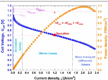
Fig. 1. Typical electrical polarization of low-temperature single H2/O2 fuel cell.
A typical electrical polarization (cell voltage Ucell, and power
density P = Ucell × j) of low-temperature single H2/O2 fuel cells is
shown in Fig. 1. The curves highlight different features: (i) the maximum cell voltage (OCV) is lower than the theoretical value predicted by thermodynamic and Nernst data, (ii) at the operation point (usually 2/3 of Pmax), at much of the high current
density can be extracted from the fuel cell, the cell voltage is significantly lower. During the normal operation of a fuel cell, if there is no drastic change of the reaction selectivity, both thermodynamic and faradaic contributions will not change. Thus, only the experimentally measured cell voltage U affects the efficiency. A cathode performs the oxygen reduction reaction (ORR), which is thermodynamically expected to start at ca. 1.2 V vs reversible hydrogen electrode (RHE). Given the sluggishness of ORR, the best activity is achieved in the potential range of 1.0-0.7 V vs RHE (the discussion about ORR is beyond the scope of this review and is documented elsewhere12).
According to Eq. (2), it becomes obvious that the main selection criteria of anode electrocatalysts for fuel cell (operating voltage optimization) is an electrooxidation with the lowest overpotential, i.e., at the lowest electrode potential (E), ideally
E < 0.5 V vs RHE.
2.2. Working principle of dual electrosynthesis in aqueous media For a long time, the electron has been theorized as a “green reactant” to perform numerous chemical transformations, from the recovery of metals to the assembly of sub-unit of molecules. To do so, we need an electrical conducting material (electrode) to serve as a delivery of electrons (when a substance needs to be reduced) or as a sink (when a substance has to release electrons). In other words, two electrodes are needed, one acting as the “working” and another one as the “counter”. Consequently, in aqueous media, the reaction of interest at either the working electrode or the counter electrode could be coupled smartly with one of the two solvent’s “wall reactions” at the counter electrode (see Section 3.1.1). More precisely, an electrooxidation at the working electrode can be coupled with the hydrogen evolution reaction (HER) at the counter electrode, or the electroreduction at the working electrode can be
combined with oxygen evolving reaction (OER) at the counter electrode. This dual electrosynthesis is termed “paired electrosynthesis”.62,65-67,70 In such a situation, the ratio of the
working and counter electrode areas should be carefully considered to avoid any parasitic/non-productive reactions such as the dissolution or degradation of the electrodes.71
Fundamentally, the polarization of an electrode (its potential being forced away from its value at open circuit) induces an electrical current flow due to electrochemical reactions at both working and counter electrode surfaces. The magnitude of the current, proportional to the amount of the chemical substance in moles (Faraday’s first law), is controlled by reaction kinetics and/or the diffusion of reactants and products, towards and away from the electrode surface.
Going through the encyclopaedia of electrochemical reactions, almost all reactions including relatively simple redox reactions and metal depositions depict a dependence on the nature of the electrode surface. Under an electrical current flow, processes occurring at the surface of a given electrode are those depending on the nature of the electrode and those that are not. The aforementioned electrochemical processes are routinely classified into two categories.72-76 First, the
outer-sphere redox processes, whereby there is no physical interaction between the redox species and electrode surface. It is influenced by the solvent and/or electrolyte properties (double layer effects) and the electron transfer occurs between two species with no bonding between them through electron tunnelling from one to the other across a solvation layer. It is benchmarked by a formal redox potential (E°′), standard rate constant (k°), and charge-transfer coefficient (α) as defined in the Butler-Volmer formalism of electrode kinetics. Second, the inner-sphere or catalytic redox processes wherein the bonding or adsorption of reactants, intermediates, and/or products to the electrode surface has a major effect on the reaction kinetics. The electron transfer occurs in an activated complex where a ligand is shared between the donor and acceptor molecules (and where the bridging ligand may or may not be transferred during the reaction). It is gauged by an overpotential (η), Tafel slope (semi-quantitative indicator of charge-transfer kinetics and/or mechanisms for simple processes), and/or exchange current density (j0, the current density at the equilibrium
potential, which is a quantitative indicator of charge transfer kinetics) as defined in the well-known Tafel equation.
It should be rationally summed up that the majority of the reactions in electrochemistry are found between these two boundaries. In the first case, the electrode acts as a donor or an acceptor of electrons. The consequence is that the reaction kinetics is expected to be independent of the electrode material, but the required electrode potential is likely to depend on the nature of the electrode material. In other words, different materials will lead to the same yield. At the industrial scale, we just need to augment the geometric surface area in order to change the conversion rate. This situation is extremely rare, if not impossible to achieve in electrochemistry. In the second one, the electrode surface acts as a catalyst (an electrocatalyst). In this case, the type and rate of the reaction depend critically on specific interactions between the electrode
surface and chemical species that are present in the electrolyte. Precisely, electrosynthesis driven by this type of interactions (electrocatalysis) is burgeoning. Instead of relying exclusively on the “geometric surface area” in the first case, one can, for the same geometric surface area, change the yield, conversion, mechanism, electrode potential (thus indirectly the consumed electrical energy). Sections 2.4 and 4 will critically examine different tools used by researchers to provide increased efficiencies, particularly the nano-structuring and the heterogeneous composition of catalytic electrodes.
2.3. Working principle of electrolysis cells for H2 production in
alkaline pH
The primary idea behind the concept of harvesting H2 from
water is that it does not involve any carbon sources. Operation under alkaline environments is expected to provide the best advantages (non-noble catalysts, cost-effective, long-term stability) compared to acid media.77 In an alkaline medium, the
balanced equation of HER is shown in Eq. (3), which highlights the critical step of H2O dissociation. From Eqs. (4)-(5), it can be
concluded that the only way to reduce the consumed electrical energy (W) is to couple the cathodic process (HER) with an efficient anodic reaction. If water is used as the sole reactant (in addition to H+ or HO− as ionic conductors), the anode process
that is OER leads to an overall system that requires at least U = 1.5 V, as shown in Fig. 2 (in theory 1.23 V (based on G) and 1.48 V (based on H)).
2H2O + 2e− → H2 + 2OH−, E°(H2O/H2) = -0.84 V vs SHE (3)
U RT 2FPV U Vm 2FV 2nFU U Q W (4) U 2.39 ) 3 W(kWh/Nm or W(kWh/kg) 26.59U (5)
where SHE is the standard reference electrode, W is the consumed electrical energy, Q is the required electrical charge,
U is the required cell voltage, n is the produced moles of H2, F
(96485 C mol−1) is the Faraday constant, V is the produced
volume of H2, Vm is the molar volume in normal conditions (T =
273.15 K, P = 101325 Pa), R (8.314 J K−1 mol−1) is the universal
gas constant. For H2, a normal cubic meter (Nm3) = 0.09 kg.
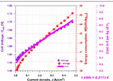
Fig. 2. Typical performance of low-temperature single water electrolysis cell.
As mentioned above, the total efficiency () of electrolysis cell has three contributions: thermodynamic (th), faradaic (F)
and voltage (U), Eq. (6). According to Eq. (7), as E(cathode) is
fixed for a given HER’s electrocatalyst, it becomes obvious that the main selection criteria of anode electrocatalysts for the purposes of electrolysis is an electrooxidation with the lowest overpotential, i.e., at the lowest electrode potential. In aqueous media, this can be achieved for a number of organic compounds such as those reviewed in the present paper. Keeping in mind that the electrolysis cell will operate in the current density range of 0.2-1.0 A cm−2, the cost associated with H2 production that is
about 8-10 €/kg(H2) (considering the mean electricity cost in
Europe, 0.2113 €/kWh78) can be also greatly reduced with the
co-production of value-added chemical(s) at the anode. To do so, the driving force behind the tight control of the “C-C” bond cleavage should be carefully understood and optimized.
U z z U H G th eq U F th 1 exp
(6))
(
)
(
anode
E
cathode
E
U
(7)where G° is the Gibbs energy, H° is the enthalpy, Ueq is the
theoretical cell voltage, U is the real cell voltage, zth is the
theoretical exchanged electrons, zexp is the experimental
exchanged electrons, E(cathode) is the potential of the cathode (negative electrode) and E(anode) is the potential of the anode (positive electrode).
2.4. Performance-by-design principles for selectivity in the electrooxidation of organics in aqueous media
In aqueous media, the first design principle for high selectivity is the proper choice of electrode material that catalyses only the oxidation of the organic molecule(s) without any interference by OER. The material should specifically be designed to function at an anode electrode potential that is not more positive than the onset potential of OER, that is EOER = 1.23 VRHE = (1.23 –
0.06×pH) VSHE (note that at 25 °C, the slope RT/F = 0.06). It
should be noted that most OER materials suffer from sluggishness that induces overpotential of at least 200 mV.
Furthermore, we should keep in mind that the theoretical onset potential can be below EHER = 0 VRHE = -0.06×pH VSHE (at 25 °C).
For example, the 2-electron oxidation of glucose to gluconate is thermodynamically expected to start at an open circuit potential (OCP) of -1.12 VSHE = -0.294 VRHE for T = 25 °C and pH =
14.50 Consequently, it might be important to add a second
designing principle in order to restrict a concomitant HER. Furthermore, the implementation of electrocatalysis in aqueous media for the selective oxidation of organics to valuable molecules could be confronted by twin processes that involve multi-electron and multi-proton transfer steps, and induce the formation of many reaction intermediates (thus energy barriers), which lead to larger overpotentials, and many reaction products. So the third designing principle should be a tight control of C-C bond cleavage. A common case is the precise engineering of advanced electrodes by a tight control over activity (meaning conversion) and selectivity, which is a crucial bottleneck in the electrocatalysis of organics. In some cases, it might be useful to alloy metals, one having higher energy than optimal value (i.e., binding energy of the performance descriptor) and another one having lower energy. Then, it is expected that the turnover and the indicators of the catalytic efficiency (described by Eqs. (8)-(11)) will increase. To sum up, a perfect electrode material for the selective electrooxidation of organic molecules in aqueous media should be able to: (i) dissociate C-H (or C-Cl, C-N, etc.) bonds with minimal driving force (i.e., with the smallest overpotential); (ii) provide O-containing (or appropriate heteroatoms) species and facilitate their reaction with the intermediates, (iii) minimize C-C bond cleavage in order to avoid obtaining a cascade of products. To achieve this, both criteria of several neighbouring but unoccupied active sites and/or the displacement of the initially adsorbed H atoms is required.
mol) (in converted reactant 1 F C) (in Q zexp exp (8) 100 mol) (in reactant initial mol) (in converted reactant (%) conversion (9) 100 mol) (in products all mol) (in product (%) y selectivit (10) 100 z 1 mol) (in converted reactant mol) (in product (%) y selectivit (11) where zexp is the experimental exchanged number of electrons,
F(= 96485 C mol−1), Qexp is the experimentally recorded
electrical charge and z is the stoichiometric number for the product of interest.
2.5. Cogeneration electrochemical devices
2.5.1. Basis of organic molecule-based fuel cells for the dual production of electricity and chemicals. When an organic molecule is used as the fuel at the anodic compartment instead of H2 (for which the net reaction product is H2O), the main
objective should not be its complete oxidation (routinely called
mineralization). Of course, a maximum faradaic yield can be achieved, but the arising question is about the future of the final oxidation product, which is CO2 (CO32- in an alkaline
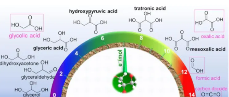
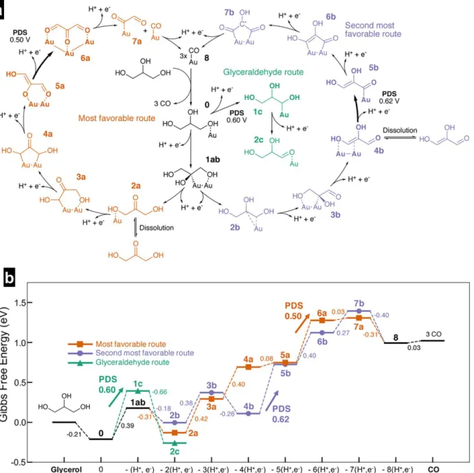
environment). Indeed, the benefits of employing a fuel cell for “sustainable electricity” production would be a paradox if a high amount of “waste” is correspondingly released. Hence, fuel cells that utilise organics should be designed to avoid the total oxidation so that the reaction product would be another organic molecule that has an added value. Fig. 3 shows the case study of glycerol, which could be concurrently converted into electricity and chemicals if a rational and smart anode’s electrocatalysts development approach is found. Therefore, it becomes obvious that the main requirement for anode electrocatalysts of organics-fuelled fuel cells switches into an electrooxidation with the lowest overpotential (ideally E < 0.5 V vs RHE) and the best C-C bond control. Conclusively, the selectivity at the anode should lead to value-added products that compensate the loss in electricity production or contribute to overall cost reduction.
Fig. 3 Sketch of glycerol electrooxidation to valuable by-products. Adapted with permission from Ref.12, Copyright 2017, Wiley-VCH Verlag GmbH &Co. KGaA,Weinheim.
2.5.2. Basis for low energy consumption organic molecule-fuelled electrolysis cells for the simultaneous production of H2 and
chemicals. There is no electricity demand for a fuel cell to operate because it is a galvanic cell that has a stock of chemical energy. In the case of an electrolysis cell, an electrical energy should be supplied. The most important idea to keep in mind when designing electrode materials to operate in an electrolysis cell as anode or cathode is to minimize the overall energy input that is proportional to the cell voltage between the anode and cathode. The majority of the organic compounds (at least those studied herein) have a lower oxidation potential in comparison to the O2/H2O couple (O2/OH- in alkaline media). Hence, one
elegant way is to electro-oxidize selectively an organic molecule at the positive electrode of the electrolyser instead of H2O, as
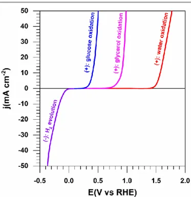
highlighted in Fig. 4. In these regards, a high purity H2 (since
there is no other gas in the reactor as it could happen for total organics oxidation at the anode) is produced at the cathode and a value-added chemical is produced at the anode. This type of strategy is so-called “co-generation or co-production” in a paired electrolysis cell.62,65-67,70
Fig. 4 Typical half-cell electrolysis polarization curves illustrating the working principle of solid alkaline membrane electrolysis cell (SAMEC), at nanomaterials. Negative electrode (cathode): Water reduction at Pt (HER, 1 M KOH, 25 °C, 5 mV s−1). Positive electrode (anode): water oxidation at Pt (OER, 1 M KOH, 25 °C, 5 mV s−1), glycerol oxidation at Au (1 M KOH + 0.5 M glycerol, 25 °C, 5 mV s−1) and glucose oxidation at Au (1 M KOH + 0.5 M glucose, 25 °C, 5 mV s−1).
3. Analytical approach for testing and validating
electrochemical performance of electrodes
Due to the lack of familiarity with electrochemistry, many chemists have been intimidated by the unfamiliar territory of electrosynthesis and by the perception that the equipment needed is complicated and expensive, which has caused researchers to turn to the use of reagents and familiar methods for which they have prior experience, even when an electrochemical method might hold a distinct advantage over that more comfortable approach.60 This section aims at
stimulating the best practices for performing and reporting the electrocatalytic performance for the electrooxidation of organics and inviting other chemists to join the landscapes offered by electrochemistry. Specifically, the section aims at providing an updated and complete portfolio for setting up electrochemical experiments. The section includes the choice of: the appropriate electrolyte, the type of the cell, and the methods of electrochemical characterization, namely cyclic voltammetry (CV), linear sweep voltammetry (LSV), chronoamperometry, chronopotentiometry, and electrochemical impedance spectroscopy (EIS). We also provide details surrounding product analysis by in/ex situ coupling methods (spectroelectrochemistry, chromatography, spectrometry, etc.).
3.1. General work-up tips for electrosynthesis in aqueous media
3.1.1. Choice of the appropriate electrolytic solution. The term “aqueous media” implies that water is the solvent. It should be of high purity (routinely called ultrapure water of ca. 18 MΩ cm at 20 °C). The ionic conductivity of that water being negligible (ca. 5.5 × 10⁻⁶ S m−1), the addition of selected species to act as
an electrolyte (also known as electrolytic solution or supporting electrolyte) is required to insure ionic conductivity (this will suppress migration effects of electroactive species under an electrical field), except the situation where the compound that will be electrolysed is actually a salt or one is using a flow cell with a very small electrode gap (micro-scale or lower). Its main function is to assist with ionic conductivity, which means that the compound is soluble in the solvent and dissociates into ions. In aqueous media, the potential window is limited by hydrogen evolution and oxygen evolution due to the overpotentials, so that the electrolyte should not undergo any oxidation, reduction or other types of degradation in this window. The electrolyte should facilitate extraction, separation and purification of the reaction products. Its concentration should be at least 0.1 M79. Of course, a lower value may be sufficient in
some cases. The presence of electrolyte is expected to minimize the uncompensated resistance; the precise determination of this resistance is an important task (Section 3.2.1.). It is very important to point out that this resistance also depends on the type of substrate and the cell geometry. For the last one, those parameters are the working electrode area and distance between two electrodes which are used to measure an electrical voltage. Besides, there are some types of flow electrolysis cells in which the use of an electrolyte can be minimized if not eliminated.66,74,80-85 To complete this subject,
whether to use an electrolyte or not and at what concentration should be decided on a case-by-case basis during control experiments. In aqueous media, the most widely used electrolytes can be inorganic salts of neutral pH (NaCl, KCl, KNO3, K2SO4, etc.), compounds with a stable pH of certain value
(buffers: phosphate, carbonate, citrate, etc.), and compounds with variable pH (acid or base: HClO4, NaOH, KOH, HCO3-, etc.).
Beware using halide anions (X−, X = Cl, Br, I) that can be oxidized
to either X2 or halonium ion (X+). In addition to the electrolyte’s
stability within the potential window, its compatibility with the reactants and products must be taken into account too (not involved in parasite reactions that can modify the kinetics/efficiency).86,87
When the electrooxidation of an organic molecule involves a “proton-coupled electron-transfer step”, the pH has a crucial impact on the activity. Seminal (electro)catalytic studies have shown that the performance of the reaction is maximal at pH close to the pKa (dissociation constant) of the organic molecule being studied.88-96 For this reason, in aqueous media, CO2 is
studied for a pH around 8 (pKa of CO2(aq) = 6.3 and 10.3), formic
acid (pKa = 3.77) about pH 4 and alcohols above pH 12 (very weak acids: pKa = 12.23, 14.15, 14.77, 15.9, for glucose, glycerol, ethylene glycol, and ethanol, respectively). It is argued that the alkoxide (anion of dissociated alcohol) is the real active
species in alkaline media.88,89,91-94 Hence, the pKa is a key
property to describe the reactivity, since it reflects the concentration of the active species (alkoxide ions). Work by de Souza et al.96 studied the reactivity of three-carbon-atom chain
alcohols on a bulk Au electrode and observed that an increase of pKa results in the decrease of the current densities.
3.1.2. Choice of the appropriate electrochemical cell setup: configuration and electrodes. There are two types of electrochemical cells, an undivided or a beaker-type cell (1 compartment), and a divided or H-type cell (2 compartments) wherein both the counter electrode and working electrode compartments are isolated by separators,97,98 e.g. a membrane,
diaphragm, etc. Indeed, in the course of an electrochemical reaction, when the oxidation occurs at the working electrode, a parallel reduction process happens at the counter electrode, while the reverse is also true. So, as the intermediate/product that is produced at the working electrode can diffuse or migrate to the counter electrode, it is strongly advised to use an H-type cell. This helps to avoid any potential transformation of the product at the counter electrode or interference with the process occurring there. Both configurations should be carefully examined when deciding to employ a three- or two-electrode setup. For a two-electrode configuration, electrodes are referred to as positive and negative electrodes. In this case, the driving force during the electrosynthesis can consist of applying either a cell voltage E(V) between those electrodes or a current. That current is routinely normalized as a current density j(A cm‒2) with respect to the limiting electrode.
Industrial-scale electrolysers mostly operate in a two-electrode configuration by applying a fixed current (the duration of the process is evaluated by the second law of Faraday). In some cases, it is more convenient to use a three-electrode setup where the introduced third electrode is the reference electrode. The potential of the reference electrode should be stable in order to enable a tight control of the potential of working electrode so that electrosynthesis can be performed correctly. This is very important in electrocatalysis where the surface state of the working electrode depends on the applied potential. Indeed, in a three-electrode configuration, the working electrode is where the investigated reaction takes place. Its feature is to allow good activity, selectivity, and durability. Notably, in aqueous media, chemical species composed of the solvent and/or electrolyte are adsorbed at the working electrode (H(ads), OH(ads)) and take part in the reaction. Except
the case of non-aqueous media, where the carbon electrodes are used for a large spectrum of reactions, the choice of the working electrode in aqueous media should be treated on a case-by-case basis. This is outlined in Section 4. For this three-electrode arrangement, the counter three-electrode ensures the circulation of the electrical current by reducing (if oxidation occurs at the working electrode and vice-versa) the solvent/electrolyte at its surface. The area ratio between the counter electrode and that of the working should be optimized
to ensure that the occurring electrochemical reaction at the counter electrode’s surface is not the overall limiting process. A ratio of at least 3 with respect to the working electrode is recommended in electrocatalysis. However, depending of the cell setup and the electrochemical process occurring at the counter electrode (much faster kinetics than the process at the working electrode), the counter electrode can have lower area. In fact, the electrooxidation of certain organic molecules in an aqueous medium could be done using just a Pt wire. Indeed, the kinetics of the evolution reaction of H2 on Pt in these conditions
is known to be very fast and not limiting. Even though Pt-based materials have been employed as the counter electrode material for many years, one should be aware of possible Pt dissolution and re-deposition at the working electrode. As an active catalyst for the majority of substrates, it will interfere with the process at the working electrode.99-101 Jerkiewicz et
al.71 have shown that, under electrochemical conditions, the
area ratio between the working electrode and the counter electrode has a noteworthy role on the dissolution of metallic species that are on the working electrode. When the active species have to be immobilized onto the working electrode surface (NPs, enzymes, etc.), the same precautions apply. When the upper potential limit is not exceeding 1.2-1.5 V vs RHE, high purity glassy carbon is an excellent choice as a counter electrode or supporting material of catalytic species (NPs, enzymes, etc.) being deposited onto the surface of the working electrode.
For the choice of the reference electrode, the most popular ones in aqueous solutions are: silver-silver chloride (Ag|AgCl|KCl, SSCE), saturated calomel electrode (Hg|Hg2Cl2|KClsat, SCE), mercury-mercurous sulphate electrode
(Hg|Hg2SO4|K2SO4, MSE), mercury-mercury oxide electrode
(Hg|HgO|Na(K)OH, MOE) and the reversible hydrogen electrode (Pt|H2|H+, RHE). All electrode potentials can be
readily converted versus RHE and vice-versa through the Nernst formula, Eq. (12). It should be stated that RHE (a pH independent RE, suited for coupled electron-proton transfer reactions, is the metric electrode for electrochemists in aqueous media. So when possible, all data should be reported with RHE. The most appropriate method to precisely determine the conversion term expressed in Eq. (13) between RHE and another reference electrode is to use the calibration curve in high-purity H2-saturated electrolyte. Typically, a steady-state CV
is recorded in H2-saturated electrolyte at a scan rate not higher
than 1 mV s−1 by employing a high purity Pt (plate, wire, etc.) as
the working electrode, another Pt or glassy carbon as the counter electrode and the targeted reference as the reference electrode. Hence, in such CVs collected at a quasi-steady state scan rate, the average of the two potentials at which the current crossed zero is taken to be the thermodynamic potential for the hydrogen electrode reactions (HER and HOR). Furthermore, the nature of materials used for the fabrication of the glassware should be carefully probed.102 The traditional approach for
organic molecules has been assumed to make use of a “salt bridge” (main role of allowing only the ionic conductivity), for example, double-junction RE or Haber-Luggin capillary tip,101,103
which is important for the chloride-based reference electrodes. For experiments in acid or neutral pHs, SCE, SSCE and MSE are recommended, but their utilization for long-term experiments should be avoided in alkaline pHs, where MOE is the best option. For chloride ions issues, MSE is the best option in lieu of SCE or SSCE. Indeed, not only trace concentrations of ions (such as chloride) might adsorb on the working electrode and dramatically change its electrochemistry, but also can alter the nature and performance of the electrochemical reaction being studied. Lastly, whilst RHE has the benefit of being filled with the electrolyte in all range of pHs, it should not be used in a single compartment cell without a salt bridge because of a possible pollution by organic molecules and gaseous products that can enter in the reference electrode, alter its potential value over time and compromise the quality of the electrochemical response. SHE) vs (V E pH F 2.3RT RE) vs E(V RHE) vs E(V (12) SHE) vs (V E pH F 2.3RT E(V) (13) where E° is the standard potential corresponding to the redox couple associated with the reference electrode (RE). For example, E°(V vs SHE) = 0.208, 0.242 and 0.640 for SSCE, SCE and MSE, respectively.
3.2. Methods of electrochemical characterization and products analysis
3.2.1. Half-cell and cell reactions characterization. Three methods can be used to run electrosynthesis: constant current electrolysis (or chronopotentiometry, applied parameter = j(A cm‒2)), constant potential electrolysis (or chronoamperometry,
applied parameter = Eappl(V vs RE) = EWE – ERE), and constant cell
voltage electrolysis (applied parameter = Uapplied(V) = EWE – ECE).
When a three-electrode arrangement is required because the potential of the working electrode needs to be monitored, the method of constant current electrolysis and constant potential electrolysis are used. Otherwise, the constant current electrolysis and constant voltage electrolysis are used for two-electrode setups. In some cases, it might be useful to substitute a constant potential electrolysis method (a single step potential) by the programmed potential electrolysis, which is made of at least two potential steps in order to manage the catalyst deactivation.13,98,104 In fact, the constant potential
electrolysis method (single step) is suitable for reactions either predominated by outer-sphere processes or performed with robust catalytic electrodes that do not suffer from the surface poisoning phenomenon. So in order to retain activity, the main
step, i.e., the reaction plateau (lasts tens of seconds), is followed by a shorter pulse (of a duration ranging from milliseconds to a second) at a more positive potential to electro-oxidize the strongly adsorbed species that were previously formed. Sometimes, a third plateau that lasts a few seconds may be necessary at more negative potentials in order to adsorb the organic molecules being studied or to deposit electrocatalytic species (ad-atoms by under potential deposition, H(as) or OH(ads)) at the surface used to regulate the
catalytic performance. It should be emphasized that the pulsed transition between different plateaux is typically executed by a simple jump of potential can be substituted by a LSV (at a scan rate of at least 100 mV s‒1).98 Note that programmed potential
electrolysis methods must be always accompanied by the single step technique of constant potential electrolysis to ensure that product distribution corresponds exactly to faradaic processes of the main plateau.
The fulfilment of an electrolysis experiment by one of these methods assumes that the molecule is reactive under the considered reaction conditions, which is not necessarily obvious. So, preliminary blank and control measurements by CV105,106 or LSV in a conventional three-electrode cell are
mandatory in order to refine the final composition of the reaction medium. CV (electrode’s potential cycling periodically between two limits at a constant scan rate of typically 1-100 mV s‒1) or LSV (electrode’s potential cycling from one value to
another one at a constant scan rate of 1-100 mV s‒1) should be
initially recorded in the electrolyte and secondly in the presence of the substrate to determine whether the reactant can be electrooxidized or not. During this experiment, the position of the oxidation peaks should be precisely determined after the ohmic drop correction.101,103,106,107 Indeed, a potential drop
between the reference and working electrodes modelled by “iR” is the result of the ohmic resistance or the uncompensated resistance (R, or RU) that depends on the conductivity of the
electrolyte as well as the geometry and arrangement of the reference and working electrodes in the cell. That uncompensated resistance is sometimes called “solution resistance (Rs)”, which should not be the case for the simple
reason that it includes contributions from the electrode connections and electrolyte. Note that the use of extension cables in addition to that of the potentiostat is strongly discouraged since it adds a layer of electrical wiring/contact resistances. However, when it is unavoidable, the length should be kept as minimal as possible. After correction by Eq. (14), the plots are usually called “iR-free voltammograms”.
E (V vs RE) I R RE) vs (V Ereal appl (14) where Eappl is the applied value, Ereal is the received value, I is
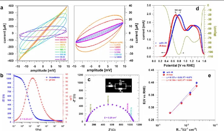
Fig. 5. Typical characterization of a half-cell reaction by EIS at OCP (0.1 M KOH + 0.1 M glucose, 25 °C). (a) Lissajous plots. (b) Bode diagrams. (c) Complex-plane Nyquist impedance plots. (d) Left y-axis: voltammograms (without and with iR drop) recorded at 50 mV s−1; right y-axis: iR drop potential. (e) Tafel plots by Rct.
The emerged and widely employed method to get R is the electrochemical impedance spectroscopy (EIS)108,109 that can be
performed in potentiostatic or galvanostatic mode. Basically, EIS is performed by scanning a range of frequencies from kHz to mHz at amplitudes of few mV for potentiostatic or few µA-mA for galvanostatic and insuring the linearity and stability of the system. Fig. 5a shows Lissajous plots of the alternative potential on x-axis and alternative current on the y-axis, which highlights the cut-off between two regimes. Even if the value of R is not impacted, this drastically changes the trends from other quantitative data and their interpretation. Visually, when the linearity condition is respected, the plot exhibits a central symmetry with respect to the origin of the plot, Fig. 5a, left side. For a non-linear response, the central symmetry of the plot is not respected, as illustrated in Fig. 5a, right side. In the Bode plot (Fig. 5b), R corresponds to the value of the impedance at the high frequency region. In a Nyquist plot (Fig. 5c); the intersection of the impedance data with the x-axis at the high frequency leads to the determination of R. There are other ways for the accessing the iR drop, namely the distance variation and the current interrupt methods.74,84,103,107 The
ohmic potential drop can then be compensated by means of a numerical post-measurement, an automatic positive feedback or a negative resistance; those methods are well explained in Ref.107 Further modelling of EIS by representative equivalent
electrical circuit is input in Fig. 5c, i.e., RΩ+QCPE//Rct wherein Rct
is the charge transfer resistance and QCPE is the constant phase
element.108,109 In fact, modelling an electrochemical
phenomenon with an ideal capacitor (C) implicitly assumes that
the surface of the electrode under investigation is homogeneous, which is rarely achievable, if not impossible. So, this lack of homogeneity is modelled with a QCPE. In some case,
it can be useful to add a Warburg element (W) in serial with Rct
whereas the Warburg impedance models the mass transport, i.e., diffusion. The metric of Rct (inversely proportional to rate
constant k°, thus to the exchange current density j0) is the ability
of the electron-transfer and the difficulty of an electrode reaction for driving larger current density with a less driving force (i.e., overpotential).74 For a given electrode, the lower Rct
is, the higher is the kinetic rate. Fig. 5d depicts the contribution of the R on the profile of a collected CV. Depending on the value of R and the magnitude of the current, the potential drop can be from few mV to hundreds of mV, which might not be negligible. This would strongly affect not only the value of the electrode potential to be applied during an electrosynthesis by the constant potential electrolysis method, but also the mechanism descriptors such as the Tafel slope b(mV dec‒1).79
The determination of Rct at different electrode potentials
and the plotting of E vs log(Rct‒1) can be used as an alternative
method110-112 to the classical E vs log(j) when accessing the value
of the Tafel slope. The use of 1/Rct is simply due to the fact that
Rct is inversely proportional to the rate constant (thus to the
current/current density too), which is a function of the applied potential for a heterogeneous electron-transfer reaction.74 Fig.
5e shows an example where b = 127 and 118 mV dec‒1 before
and after iR-drop correction, respectively. Furthermore, the description of the CV of an organic molecule can be finalized by collecting CVs for different scan rates v = 1-200 mV s‒1 andby
plotting log(jpeak) vs log(v) where: (i) slope = 1 means that the
reaction is limited by adsorption (reactants), (ii) slope = 0.5 means that the reaction is limited by diffusion (reactants and products), (iii) slope = 0.5-1 means that the reaction is limited by both adsorption and diffusion, and (iv) slope < 0.5 is translated to as a complex process (adsorption, diffusion, electron transfer). In tandem with classic CV/LSV for substrate and electrolyte concentration effects (orders of reaction, etc.), experiments should be performed at different temperatures for the assessment of the electrochemical activation energy, an important kinetic parameter indicating the activation energy barrier to overcome before the reaction occurs.51 Finally, as a
routine, solutions should be outgassed by bubbling an inert gas such as Ar or N2 prior to electrochemical measurements (the
use of N2 should be justified for low potentials, E < -0.7 V vs RHE,
since the catalysts could be active for the electrocatalytic N2
reduction reaction, thus modifying the efficiency).113,114
3.2.2. Multivariate intermediates and products analysis: in-situ versus ex-situ. Traditional “pure electrochemical methods” (CV, LSV, etc.), whereby electrode activity and dynamics can be visualized in the form of graph, do not provide any specific information on the products and/or intermediates. Whereas ex
situ methods allow assessing the final product(s), the use of in situ measurements helps to rationalize an electrochemical
process in order to determine the reaction mechanism. The coupling of electrochemical measurements with spectroscopic, spectrometric and chromatographic methods enables improved understanding of the electrochemical processes at the electrode-electrolyte interface and more importantly, the governing mechanism. Spectroelectrochemistry, i.e., the coupling, for example, of Fourier transform infrared spectroscopy (FTIRS) to electrochemistry experiments is an advanced online technique that enables one to qualitatively assess the nature of the reaction products/intermediates and determine the best electrode potential to be applied for bulk electrolysis during a constant potential electrolysis program. Indeed, high-performance liquid chromatography (HPLC, HPLIC), mass spectrometry (MS) and nuclear magnetic resonance (NMR) give only the final and stable reaction products in solution. Spectroelectrochemistry, however, provides relevant and temporal data of high resolution that can be correlated directly with the underlying reaction pathways during an organic molecule electrooxidation.115-119 Depending
on the configuration, it can enable the identification of adsorbed species on the electrode surface owing to their interaction with the radiation. A three-electrode spectroelectrochemical cell typically has a CaF2 infrared (IR)
transparent window allowing the beam to pass through a thin layer of electrolyte and to be reflected at an incidence angle. The working electrode consists of a catalytic ink deposited onto a highly reflecting support pressed against the CaF2 window to
obtain a thin layer of electrolytic solution in order to avoid excessive IR beam absorption. Those temporally resolved
spectra can be recorded in two different ways. Scanning the electrode potential through CV or LSV known as “single potential alteration infrared spectra (SPAIRS)” is the first method. It consists of recording the electrode reflectivity at different potentials in steps of 10-100 mV at a quasi-steady state scan rate of 0.5-2 mV s‒1. Fixing the potential/current and
recording spectra at different dwelling times of few seconds to minutes is the second method. Although the data from spectroelectrochemistry are temporally resolved, the approach however often provides qualitative results in addition to the frequent overlaps and uncertainties in the assignment of the bands. Another method might be differential or online electrochemical mass spectrometry (DEMS, OLEMS), which allows for the identification of volatile species.120,121 Given that
the products are not always volatile and intermediates of short lifetime cannot be detected and quantified by DEMS, HPLC (elution by acidic force) and HPLIC (elution by conductivity strength) seem to be the appropriate techniques for investigating the organic molecules oxidation products (aldehydes, ketones, and carboxylic acids) both at a qualitative and quantitative levels, performed offline13,51,120-123 and even
online.124 After bulk electrolysis, in addition to standard
separation/purification methods, samples from the reaction media could be passed through an ionic resin to remove electrolytic salts; in the case of alkaline solutions, carboxylates are converted to their protonated forms. The recovered aqueous solution containing the organic species is frozen and lyophilized to remove water by sublimation. Few attempts have been reported for the isolation of the reaction products;36 this
well-known practical problem can be very strenuous in aqueous media.50 Furthermore, the ex situ analysis by LC-MS in negative
or positive ionization mode enables the determination of the molecular weight of the products. Standard 1D and 2D NMR techniques of 1H, 13C, 1H-1H, 1H-13C, and DEPT-135 (to
differentiate CH3 and CH signals to that of CH2) as well as other
heteroatoms’ NMR enable to improve assignments towards an unambiguous identification.
4. Advancements in C2 and C3 alcohols
electrocatalysis for organic electrosynthesis
4.1. Nanostructured electrocatalysts for active and selective C2 and C3 alcohols oxidation
The range of materials that have been explored for the oxidation of C2-C3 alcohols is relatively broad, ranging from “platinum group” or “noble” metals to transition metals and those within the buzzword of “metal-free”. When the main idea behind the development of nanostructured catalysts for the oxidation of organic molecules is the efficiency with the lowest overpotential and the best selectivity towards value-added product(s), any practical electrode materials should contain at least one element from Pt, Pd, Ru, Rh, and Au. Of course, a catalyst without those elements can be used, but an efficient catalytic activity can be reached only at relatively high electrode
potentials, about 1.3-1.9 V vs RHE,90,125-128 where the carbon
support corrosion and C-C bond cleavage are highly probable. In the following discussions, we intentionally focus on the realistic systems of noble metals in the form of monometallic, alloy, core-shell, or porous at nanoscale.
The use of bulk polycrystalline and single-crystal surfaces for electrocatalytic processes serve only as guidelines to assess the performance descriptors. For a practical deployment, cost-effective materials based on nanostructured interfaces should be found. Furthermore, the design principles to tailor such advanced electrocatalysts should allow the presence of terraces, defects, nanoparticles (NPs) polydispersity, shapes, morphologies and compositions. The improvement in activity of pure monometallic M1 (M1 = Pt, Pd, Ru, Rh, Au) catalysts due to
the presence of a second metal M2 (from transition metals to
those of the previous list) is thought to be a combination of a bifunctional mechanism and ligand effects.18,20,26,129-141
According to the bifunctional effect, a partially oxidized transition metal M2 provides oxygenated species (M2-(OH)x)
which allow the optimal oxidation. In heterogeneous electrocatalysis, this is known as the Langmuir-Hinshelwood mechanism. On the other side, the ligand effect considerations imply that the second metal M2 leads to changes in the
electronic structure of the main metal M1, which entail the
weakening of the M1-intermediate (product) bond. Hence, any
strategy to obtain a high-performance material should advisedly be based on these two approaches. Among the different methods for the preparation of nanoelectrocatalysts, the use of colloidal routes is the most conventional approach. These methods are characterized by the chemical reduction of the metallic precursor in the presence of a capping agent or surfactant, electrodeposition, radiolysis, decomposition of bulk metals into NPs (laser ablation) and atomic layer deposition (ALD) routes.13-16,18-20,119,122,127,136,142-171 Different carbon
substrates based on Vulcan, Ketjenblack, nanotubes, graphene are currently used in catalysis. The goal is to achieve a good dispersion of NPs, minimal amount of the metal content and good support-active site interactions. Those substrates are electrically conductive, chemically stable and have high BET surface area (few hundreds of square meter per gram). Vulcan types are XC 72 and 72R172,173, and the metal content goes from
20 to 60 wt.%. It should be noted that in gas-phase heterogeneous catalysis (activation results from temperature or pressure change), the metal loading on the support is typically 0.1-1 wt.%. However, because of the reduced mass-transport rates of the reactant molecules in the liquid phase (electrocatalysis) versus the gas phase, the metal content in an electrocatalyst must be at least 10 wt.%.79 Furthermore, if
Vulcan will be used as support, it is highly desired to perform a thermal pre-treatment to remove potential contaminants coming from the industrial manufacturing process such as sulphur. It also augments the electrochemically active surface area (ECSA) and catalytic activity of metallic NPs such as Pt. 174
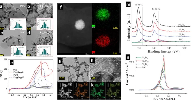
Figs. 6a-d show the transmission electron microscopy (TEM) images of Pt-Pd-Ru/C synthesized by the microwave-assisted heating method,16,175 which involves a mixture of metal
precursors, propylene glycol (solvent and reductant), Vulcan XC
72, sodium acetate (stabilizing agent), sodium hydroxide (to reach a pH of 10) and hydrazine (co-reducing agent). From Fig. 6e, it can be observed that the presence of Ru notably boosts the electroactivity of Pd and Pt; the mass current density at the peak follows the order Pt86Ru14/C > Pd71Ru29/C > Pd/C > Pt/C. It
can also be seen that Pt86Ru14/C has at least 100 mV negative
shift of the onset potential (0.5 V vs RHE compared to 0.6-0.7 V vs RHE for other electrodes). Since the NPs have the same size distribution of 2-5 nm, the significant improvement of the electrocatalytic activity for bimetallic systems can be explained by a dual combination of bifunctional and ligand effects. The difference in terms of the onset potential when Ru is associated with Pt or Pd should result from an initial step that obviously does not occur at Ru actives sites. This activation undoubtedly has a correlation with the adsorption of glycerol and more likely OH− since Pt-OH species can be formed at a lower potential than
Pd-OH, which has been routinely used to explain the excellent oxidation of CO in alkaline media at E ≤ 0.5 V vs RHE.119 The
materials reported by Palma et al.16 have been found to exhibit
good stability in 1 M NaOH + 0.5 M glycerol as determined by controlled potential electrolysis at E = 0.7 V vs RHE. Electrolysis in a H-type Pyrex cell using an anion-exchange membrane (Fumasep, FAA, Fumatech) and HPLC analysis reveal that the major oxidation product is glycerate (4-electron selectivity) at Pd-based electrodes and 1,3-dihydroxyacetone (DHA) at Pt-based electrodes. The results imply that the adsorption of glycerol occurs through either one of the primary alcohol function at the extremity of the molecule or the secondary alcohol function, depending of the nature and the composition of the electrode. Those trends in selectivity are in agreement with seminal observations at bulk and nano-electrodes in alkaline media.116,118,121,176 Koper’s group combined online
HPLC, OLEM and spectroelectrochemistry to show that on the Pt(111) electrode, glyceraldehyde, glyceric acid, and DHA are the products of glycerol oxidation, while on the Pt(100) electrode, glyceraldehyde was detected as the main product of the reaction in acidic media.176 Glyceraldehyde is not a stable
compound in alkaline media, undergoing a conversion into glycerate. Furthermore, Bi has been found to be a co-catalyst that induces a 2-electron pathway by the secondary alcohol group of glycerol into DHA.118
There was no direct physicochemical evidence that the catalysts reported by Palma et al.16 are alloy, core-shell or
“simple bimetallic (made of individual particles)” systems. Figs. 6f-l show examples of alloy phases that have been screened for C1-C3 electrooxidation (methanol, ethanol, ethylene glycol, and glycerol) in alkaline media. Fig. 6f displays the high-angle annular dark field aberration-corrected scanning transmission electron microscopy (HAADF-STEM) coupled energy dispersive X-ray spectroscopy (EDS) elemental mapping images of CNTs supported PdAg NPs, prepared by an aqueous-phase reduction method.177,178 Those of the unsupported PdPt nanowire
networks136 are reported in Figs. 6e-l. It was found from X-ray
photoelectron spectroscopy (XPS) that the alloying of Ag to Pd prevents the oxidation of Pd atoms leading to metallic Pd(0), while the majority of the Pd surface in the monometallic Pd/CNT is in the oxidized state Pd(+II).177 As shown in Fig. 6m, the

![Fig. 9. (a) Direct ethanol fuel cell performance (5.29 cm 2 , 80 °C, Nafion® 117 PEM) at Pt/C-ETECK cathode (humidified O 2 , P O2 = 2.0 bar, flow = 60 mL min −1 ) and different anodes ([EtOH] = 2.0 M, P EtOH = 1.0 bar, 60 mL min −1 )](https://thumb-eu.123doks.com/thumbv2/123doknet/14777695.594691/19.892.62.822.87.438/direct-ethanol-performance-nafion-eteck-cathode-humidified-different.webp)
