Publisher’s version / Version de l'éditeur:
Vous avez des questions? Nous pouvons vous aider. Pour communiquer directement avec un auteur, consultez la première page de la revue dans laquelle son article a été publié afin de trouver ses coordonnées. Si vous n’arrivez pas à les repérer, communiquez avec nous à PublicationsArchive-ArchivesPublications@nrc-cnrc.gc.ca.
Questions? Contact the NRC Publications Archive team at
PublicationsArchive-ArchivesPublications@nrc-cnrc.gc.ca. If you wish to email the authors directly, please see the first page of the publication for their contact information.
https://publications-cnrc.canada.ca/fra/droits
L’accès à ce site Web et l’utilisation de son contenu sont assujettis aux conditions présentées dans le site LISEZ CES CONDITIONS ATTENTIVEMENT AVANT D’UTILISER CE SITE WEB.
Building Note (National Research Council of Canada. Division of Building Research), 1950-04-05
READ THESE TERMS AND CONDITIONS CAREFULLY BEFORE USING THIS WEBSITE. https://nrc-publications.canada.ca/eng/copyright
NRC Publications Archive Record / Notice des Archives des publications du CNRC :
https://nrc-publications.canada.ca/eng/view/object/?id=5c1cd4de-208e-4570-86f3-d36ac9f37b0b https://publications-cnrc.canada.ca/fra/voir/objet/?id=5c1cd4de-208e-4570-86f3-d36ac9f37b0b
NRC Publications Archive
Archives des publications du CNRC
This publication could be one of several versions: author’s original, accepted manuscript or the publisher’s version. / La version de cette publication peut être l’une des suivantes : la version prépublication de l’auteur, la version acceptée du manuscrit ou la version de l’éditeur.
Access and use of this website and the material on it are subject to the Terms and Conditions set forth at
Instruments for measurement of dynamic stresses (or strains) in temporary steel structures
Ser TH1 392 no. 7 e. 2
,m
INSTRWEMTS FOR~ A S ~
OF
E D ~ A M I C STRESSES ~ T(OR
STRAUS)IN
TENPORARY STEELSTRUCTURES
by
W.
R. Schriever
Abstract
Measurement
of
s t r e s s e s in temporarysteel
stnzctures,such
as girders, struts and p i l e s , used d u r i n g construction of t h e Yonge Street Sub- way a r e being made in co-operatian with t h eToronto
T r a n s p o r t a t i o n Commission,while
stressesdue to dead lead and e a r t h pressure
a r e
static, it is necessary to o b t a i n a continuous s t r a i nrecord
by meansof
an
oscillograph t o determine t h eaddi-
t i o n a l dynamic s t r e s s e s due t o
live load,
The ob-j e c t i v e is to ascertain t h e
maximum
stresses and t h e frequencyof
theiroccurrence
in o r d e rto cam-
p u t e t h e
maximum
l o a d s and their d i s t r i b u t i o n todetermine whether t h e design l o a d s used at present
a r e t o o conservative, S u i t a b l e i n s t r u m e n t s
which
could b e used
f o r such an
investigation a r e des-c r i b e d a n d
relative merits
o f t h e equipmenta r e
discussed.
Lists of manufacturersof
s t r a i ngauges and amplifying and recording equipment
a r e
included,'
33y535-/
IN
STRWdlX4TS FOR 14EA5URmEi4TOF
DYNAV!IC STRfiSS&S(OR
STRAIN) I N THfl TrnPOBARY STZEL STRUCTURESby
W.
R , SchrieverIntroduction
& I
The,construction of the Yonge S t r e e t Subway by t h e
Toronto T r a n s p o r t a t i o n Commission provides an unusual opportunity to i n v e s t i ' g a t e soil a n d foundation conditions in t h e Toronto a r e a and to study some r e l a t e d d e s i g n and construction problems. A orogramme o f co-operative work was therefore suggested by t h e
N a t i o n a l Research Council and the T o r o n t g Transportation Commis-
s i o n , t h e results o f which
will
contribute to the knowledge in this f i e l dof
engineering in g e n e r a l a n d will be of v a l u e t o t h econstruction i n d u s t r y o f Canada as
well
a s to the Toronto Trans- portation Commission,Among
the
l i s t o f investigations is t h e measurement o fstresses in the temporary structures, such as girders, struts and p i l e s used in the
cut-and-cover
method. Measurement of s t r e s s e s in these members is b e i n g c a r r i e d out fortwo
purposes:(1)
A s a check of t h e d e s i - s n of t h e temporary structures, i.e. in o r d e r to compare a c t u a l stresses w i t h allow- a b l e s t r e s s e s .( 2 ) In o r d e r to d e t e r m i n e t h e e a r t h pressure a c t i n g
on
the sides of the subway excavation under v a r i o u s conditions-
VY%ile the stresses due t o dead l o a d and e a r t h pressure are s t a t i c , t h e s t r e s s e s due t o l i v e l o a d ( s t r e e t c a r a n d motor t r a f f i c ) a r e transient a n d a l s o , to
a
c e r t a i n extent, oscillating, dependins on shock effects of t h e t r a f f i c and the vibrationcharacteristics
of
t h e d e c k . Therefore, w h i l e it is sufficientto measure the s t a t i c stresses periodically b y means o f a mecha-
n i c a l
s t r a i n
gauge, . it i s necessary t d o b t a i na
continuous s t r a i nrecord
by means ofan
o s c i l l o g r a p h to determine t h e a d d i t i o n a ldynamic stresses due to live l o a d w i t h t h e a i m o f f i n d i n g t h e maximum stresses occurring a n d the frequency of t h e i r occurrence,
Only
in this way is it p o s s i b l e to coinputs, from t h e determined maximum stresses, the m a x i m u m l o a d s a n d their distribution andt h u s to find o u t w h e t h e r t h e d e s i g n l o a d s used
at
p r e s e n t a r e t o o conservative.F o r t h e measurement o f t h e s t a t i c s t r a i n s , an $-inch
b e i n g
used which
measures t h ed i s t a n c e ,
or change ofdistance, of
t w o small
holes drilled
into the s t e e l . F a r the measurement oft h e dynamic s t r a i n s , it i s intended to u s e
electrical
gauges;e i t h e r r n a ~ n e t i c o r resistance
strain
gauges. b i a s n e t i c (or in-d u c t 2 n c e )
s t r a i n
gauges andalso
unbonded w i r e r e s i s t a n c e s t r a i ngauges have
a
better longlife
s t a b i l i t y and are more rugged than bonded wire resistancestrain
gauges, a l t h o u g h t h e latter a r emuch lower in c o s t . The o u t p u t of t h e gauges
(or
b a l a n c i n g S r i d g e circuit)is
u s u a l l y amplified a n d . c a n t h e n be fed into an o s c i l - l o g r a p h recorder, o f whichthere
a r e a greatv a r i e t y
o f types.The question of the rhost s u i t a b l e equipment f o r the present investigation i s a v e r y i m p o r t a n t one. Kuch h e l p f u l
in-
f e n n a t i o n h a s been received by c o r r e s n o n d e n c e and during discussionso f this problem. Considerable time h a s been s p e n t on a thorough study o f
this
information, which i s b e l i e v e d to beof
such v a l u e , n o t o n l yin t h e
present work but a l s o forfuture
r e f e r e n c e , t h a t i twas decided t o p r e p a r e
a
summary, which is now presentedin
this B u i l d i n g Note.In
view
o f the large expenditureinvolved,in
t h e pur- chase of this equipment ( a s - a multichannel instrumentis
requrired)a n d t h e i m p o r t a n c e o f
the
inst?uments, n o t o n l y for the p r e s e n t work but a l s o f o r o t h e r u s e s in t h eDivision
of Building Researchlater
on, t h i s Noteis
s e n t to a l l thosewho
contributed tothis
i n f o r m a t i o n
and
to o t h e r i n t e r e s t e d persons. Go:aments and sug--
gestions a r e welcomed from readers, as they
will
facilitate thed e c i s i o n on t h e equipment best suited f o r this work.
In
the mean- t i m e , while this Mote is u n d e r consideration, it is hoped that it w i l l b e p o s s i b l e toc a r r y out
a
preliminary test with borrowed instruments, so t h a t on the b a s i s of t h e comments received and t h e r e s u l t s of t h e prelimjnary test,a
well-founded d e c i s i o n will be p o s s i b l e ,Acknowledgements
The s u b j e c t matter
has
been discussed with a number o f p e o p l e working i n t h i s f i e l d who have contributedinvaluable
i n -formation, which is gratefully acknowledged. T h e list includes ~e
f
oxlowing:Kr, H.C,Ross,
Dr.
A,D,Hogg, a n dMr.
W,L.Gibson, StructuralRe-
search D e p a r t m e n t ,
H
.Z.P .C,
O n t a r i o , Toronto, O n t ,14r. "!.J.Turnbull, S o i l s
Division,
U.S. Corps o f ~ngineers, Water-ways Experiment S t a t i o n , Yicksburg, TJIiss,
Dr.
F .Tit .Lea, 3 u i l d i n g Research S t a t i o n , G a r s t o n ,G.
VJatf o r d ,Nr. R.F.Blanks, Research
and GeolopyDivision,
U . 3 . aureau ofReclamation, Denver,
C o l .
Dr.
V.H.Glanville,
RoadResearch
Laboratory,Harmondsworth,
Kiddlesex, England.
Dr.
F-Aughtie, The Institution of E l e c t r i c a l Engineers, Savoy P l a c e , V i c t o r i a Embankment, London,!!'.
C. 2, England.D r . T.W.lpJ,'lodek, Department
of
Resources and Development, O t t a w a ,Ontario. - :
Dr.
O.V.Ellis
and ICr. P.E.Cavanagh, Ontario ResearchFoundation,
T o r o n t o , O n t a r i o
Nr.
D.E.Paasons,U.S.Bureau
of Standards, Washington, D . C .F4r.
H
.
B
. S u t h e r l a n d , Dept.
of Civil
engineer in^, The U n i v e r s i t y ,Glasgow, Scotland.
J
B.G.Ballard
a n dKessrs.
C.F . P a t t e r s o n , F .G .Creed, andN
.L.
h ~ s t e r s , Division of Radio and
Electrical
E n g i n e e r i n g , National Research C o ! ~ n c i l , Ottawa.Kessrs. W.J.
Cox,
F,R.Thurston, andJ.P.Uffen,
Division of Mechanical En~ineerins,National Research
Council, O t t a w a .and a number
of
a q e n t s of manufacturers of strain measuring andMeasurement of
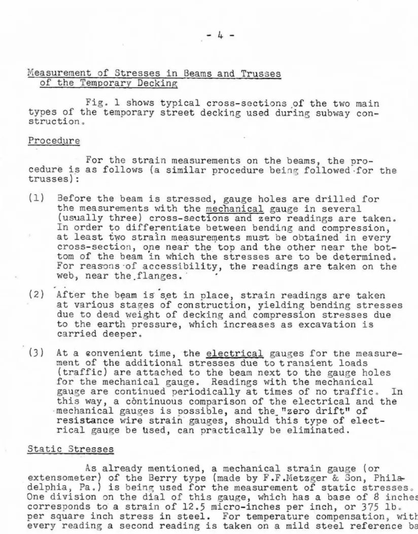
Stresses
in Beamsand Trusses
o f t h e Temporary
deck in^
Fig.
1 shows t y p i c a l cross-sections-of the
t w omain
types af She temporary s t r e e td e c k i n g used
d u r i n g subway con- s t r u c t i o n .F o r t h e strain measurements
on
t h e beams, the p r o -cedure is a s follows ( a s i m i l a r procedure b e i n ? followed-for the trusses] :
3efore the beam
is
stressed, gauge h o l e s a r e d r i l l e d forthe measurements with the mechanical gauge in s e v e r a l
( u s u a l l y three) cross-sections and z e r o readlngs
are
taken. I n order to d i f f e r e n t i a t e between bending and compression, at least two s t r a h measurements must be o b t a i n e d in e v e r y c r o s s - s e c t i o n , ope near t h e top and the o t h e rn e a r
the b o t - tom o f the beam in which the s t r e s s e s are to be determined,For r e a m n s - o f : accessibility, the r e a d i n g s a r e t a k e n
on
theweb.,
near t h e -flanges, ' * -( 2 ) Aft'er t h e beam
is
'sat i n place, s t r a i n readings a r e taken a tv s r i o u s
s t a g e s o f c o n s t r u c t i o n , y i e l d i n g bending s t r e s s e sdue to dead weight o f d e c k i n g and compression stresses due to the e a r t h pressure,
which
increases a s e x c a v a t i o n is carried deeper.( 3 At
a
o o n v e n i e n t time, t h e e l e c t r i c a l gauses f o r t h e measure- nent of t h e additional stresses due to t r a n s i e n t l o a d s(traffic) a r e a t t a c h e d to the
beam
next tothe
gauge h o l e sf o r t h e mechanical gauge. Readings w i t h the mechanical
gauge
are
continued p e r i o d i c a l l y at timesof
no traffic. I nt h i s way, a c b n t i n u ~ u s comparison of t h e
electrical
and the-mechantcal
gau,yes is ~ o s s i b l e , and t h e - " z e r odriftw of
resistance w i r e s t r a i n gauqes,should
this t y p e of e l e c t -rical gauge be bsed, can pr3ctically b e e l i m i n a t e d . Static Stresses
As already mentioned, a mechanical
strain
gauge ( o r extensometer) of the Berry t y p e [made by F .F . N e t z g e r &L Son, Phil*d e l p h i a ,
Pa,
) is being u s e d f o r the measurementof
static s t r e s s e s ,One
d i v i s i o n on the dial of this gauge, which hasa
base of8
inches,corresponds to a s t r a i n o f 1 2 . 5 micro-inches per inch, o r
375
I b .per square inch stress in s t e e l . Far t e m p e r a t u r e compensation, with e v e r y r e a d i n g a second r e a d i n g is t a k e n on a m i l d steel reference b a r ,
which is put on
the
structural member sothat
itwill
assumet h e same temperature
as
t h emember.
Stresses due to T r a f f i c Load
An important question in t h e selection o f the recording equipment is t h e type o f stresses t o b e recorded, i,e, t h e i r
v a r i a t i o n w i t h t i m e ,
The n a t u r e of t h e stresses caused by s t r e e t c a r a n d motor
traffic is
similar
to t h e s t r e s s e s due t oLive
l o a din
r a i l w a y a n dhishrvay b r i d c e s ,
A
wheel of e i t h e r a s t r e e t c a r o r an automobile p a s s i n 3 o v e r a beam of t h e d e c k i n g causes strains which c o n s i s to f a p a r t , caused b y t h e static load of t h e w h e e l c o m i n g
on (and o f f )
and
a superimposed p a r t due to the v i b r a t i o n o f thebeam when excited b y shock effects r e s u l t i n g from the r o u s h n e s s
of
t h e s u r f a c e on which thewheel
travels. A s a n e x a m ~ l e , af i g u r e from
a
paper e n t i t l e d "Description and Analysis af t h e3 r i d c e Impact T e s t s made by t h e Pennsylvania R a i l r o a d at Chester,
Pa.!'
(proceedings o f Che AmericanRailway
Engineering -?ssociation,19k1,
paTe432)
is reproduced as F i g . 2in
this Note, showing s t r a i n s in a plate g i r d k r of5 5
feet LO i n c h e s span measuredin
the middle o f t h e s p a n by means o f m s g n e t i c strain gauTes (inst- ruments No.
1,
2, 3 ,
a n d4 )
acd a l s o vertical a n d lateral de- f l e c t i o n s measured by instruments of a d i f f e r e n t principle(instruments
No, 5
and61
.
These s t r a i n s resulted f r o m the t r a n -s i e n t load of
a
steam Locomotive t r a v e l l i n ~ at a speed of46
milesp e r h o u r .
F o r t h e beams o f t h e temporary subway d e c k i n s , i t is n o t q u i t e c l e a r , at t h e p r e s e n t s t a E e of construction, how impor-
t a n t , i.e, how l a r y e , t h e superimposed v i b r a t i o n a l p m t o f t h e stress is compared w i t h the mean stress as illustrsted in F i g , 2,
In
view of the h i ~ h c o s t of oscillograph e q u i p m e n t , one must a s k , of course, w h e t h e r the vibrztional part o fthe
stress is of ar n a ~ n i t u d e which would j u s t i f y
more
e x p e n s i v e equipment thanwould
b e required'to measure the mean stress. However, it seems t h a t
oscillographs with a low frequency response ( e , % . E s t e r l i n e A n ~ u s
Recording I'iilliameters, r e s p o n s e t i m e 0.5 -1 s e c m d ) are n o t much
lower
i n c o s t than direct-writins oscillographs 7;:ith a medium f r e q u e n c y r e s p o n s e ( e , ? , BrushOscillograph,
frequency response c l a i m e dup
t o 120 c y c l e s per second). T h e r e f o r e , especially with regard t o - o t h e r uses of t h e strain recording equipment l a t e r on, a t y p e o f instrument c o v e s i n s medium frequencies often occurring in structural work would b emuch
p r e f e r a b l e .An idea o f t h e frequencies to be expected in the beams
o f t h e temporary subway d e c k i n 5 was o b t a i n e d by recording the vi- bration o f one of the beams under traffic by means of a portable Leet Seismographe The result w a s
a
n a t u r a l
f r e q u e n c y of a p p r o x i - m a t e l y45
c y c l e s p e r second,P i a ~ n i t u d e .--
of
+-.---Traffic
LoadsIt
has
a l r e a d ybeen
mentioned t h a t thes t r a i n s
are b e i n gmeasured
in
several cross-sections o fa
beam. T h i s i s done b e - cause it is intended not only to find t h emaximum
stresses but also to determine f r o m t h e s e stresses the maximum traffic l o a d st h a t occur and t h e i r distribution. I n this way it w i l l be possible to ascertain whether t h e design Loads used
at
p r e s e n t have beenr e a c h e d or not, i , e , w h e t h e r they s h o u l d be r e t a d n e d
or
reduced inf u t u r e d e s i ~ n ,
The distribution o f a l o a d acting upon a d e c k i n g beam can b e determined f r o m t h e b e n d i n g moment d i a ~ r a m , found f r o m
stresses. As this can b e done w i t h reasonable accuracy only if
t h e stresses a r e known
i n a
number o f cross-sections, t h e stresses a r e measured at t h e c e n t e r and at the q u a r t e r points o f the b e a m ,T h i s means a minimum o f six gauge lines f o r a beam in which t h e
strains must b e recarded
in
o r d e r to find simultaneous stress oeaks. Therefore a m e c h a n i c a l oscillogra?h r e c o r d e r is r e q u i r e d . As each c h a n n e l is a p r a c t i c a l l y s e p a r a t e unlt composed o f t h e active gause, the dummy gauge, the balancing bridse and itspower s u p p l y (sometimes c o n t a i n e d
in
t h e amplifier box), t h eam-
p l i f i e r and t h e oscillograph recorder, t h e h i g h c o s t o f asix
c h a n n e l
installation
is understandable. InstrumentsOn t h e f o l l o w i n g ages are lists of a p p r o p r i a t e instru- ments (gauyes and recorders
7
produced by manufacturers of straingauzes and amplifying and recording equipment. Also s e t out a r e references on the subject matter. These l i s t s and references
have been
compiled
on Ghe b a s i s o f information kindly s u b m i t t e d ba
number of those i n t e r e s t e d inthe p r o b l e m
( s e e acknowJledgernentswith
a view t o g i v i n ~ complete information r e g a r d i n g the variousi
availableinstruments,
No complete i n f o r m a t i o n can b e given r e g a r d i n g t h e
com-
p a r a t i v e c o s t o f v a r i o u s makes of instruments, a s t h e c o s t o f only
a f e w of them
is
known to the writer. T h e c o s t o f asix
c h a n n e linstallation w i t h
6
magnetic and6
balancing
gauges, ( c a l i b r a t i n gs t a n d e x t r a )
in
Canadian funds, sales t a x and transportationextra,
is as
follows:
Hathaway (photo~raphic r e c o r d ) Approximately
-
$
6,B00,00General. Electric ( p h o t o , r e c o r d ) tt
-
€?,6OO,QOk a r u s h (direct-writin? r e c o r d ) 11
-
8,300,00Conclusion
Assuming that t h e measurement of t h e v i b r a t i o n part o f
t h e
transient
stresses is desirable, it is thought at the present time that magnetic strain gauges and an oscillograph u s i n qa
direct t w i t i n g recbrder witha
frequency response of s o m e w h a t more than50 c y c l e s p e r second
would
b e the most s u i t a b l e for t h e i n v e s t i - gations described in t h i s Note.MANUFACTURERS OF
STRAIN GAUGESDe
Forest Scratch Gauge: Baldwin Southwask Division, B a l d w i nLocomotive Works, P h i l a d e l y h i a 42, Penn, I n d e n t o r Type L o a d
Cell:
No
commercial make.Bonded
Wire
Resistance Gauge: . SR-4 Gauge-
2aLdwin Southwzrk ( seeabove)
Ru~re-de F o r e s t f n c , , 76 F4assachusetts ~ v e . 3 , Cambridge,
Mass,
DeHaviland P r o p e l l e r s L t d , , H a t f i e l d
Airodrarne, H a r t f o r d s h i r e ,
Zngland,
Unbonded Wire R e s i s t a n c e Gauge: Dr, Roy
W,
Carlson, E n s i n e e r i n g 16aterial.L a b o r a t o r y , U n i v e r s i t y o f C a l i f o r n i a , 3erkeLey, C a l i f o r n i a .
Statham Laborakories, 9g23 S a n t a I4onica
a l v d . , 3everly H i l l s , California, Magnetic S t r a i n Gauge: Hathaway I n s t r u m e n t Co.,
1315
SouthCharkson St,, Denver, Colorado,
West5nghouse Electric Company, P i t t s - burgh, Penn,
G e n e r a l Electric Company, Apparatus D e p t , ,
MANUFACTUREXS
9F
ATulPLIFY1N G A N D RECORIIIIJG EGUIPNKKTEquipment w i t h pen-and-ink r e c o r d e r s :
3rush Development Co., 3405 P e r k i n s Ave., Cleveland
14,
Ohio. Henry Hughes a n d Son L t d , , 2 Claxton St., London 3YJ01.
E n g l a n d . Equipment with galvanometer oscillogrsphs:Hathaway Instrument Co., 1315 S o u t h C l a r k s o n St., Denver, C o l .
Savase and P a r s o n s Ltd., Vlatford Bypass, Herts., ~ l i ~ . ( u p to 1000 c / s )
i l i a 1 Co Pasadena,
California,
Consolidated Enqineering Corp., 620 I i o r t h Lake A v e . , Pasadena
4 ,
C a l i f o r n i a ,
H e i l a n d
Instrument
Go,, Oenver, C o l o r a d o ,G e n e r a l X l q c t r i c Company, Apparetus Dept., Schenectady,
N
.
Y o
V e s t i n g h o u s e X l e c t r i c Company, Pittsburgh, Penn, Equipment
~ 5 t h
c a t h o d e r a y oscillo%raphs:Avirno L t d , , Tauntan,
Somerset,
E n s l a n d ,( 1 5
c h a n n e l instrument) Southern I n s t r u m e n t s L t d . , F e r n h i l l , Hawley, Camberley, Surrey, E q l a n d .Mullard Electronic P r o d u c t s , C e n t u r y House, Shaftesbury Avenue,
London
PJ, C
,2, Enyland ,FurzehiEl L a b o r a t o r i e s
Ltd,
,
3orcham
Wood, Hests,, E n s l a n d , Not S p e c i f i e d :DeHaviland P r o p e l l e r s L t d . , H a t f i e l d Aerodrome, Hertfordshire,
Eng.
Trimount I n s t r m e n t Co.,
37
TI, Van Buren St,, Chicago 5,lllinois (arnglifiers
only)REFERENCES
S o c i e t y
for
ExperimentalStress Analysis
-
Proceedin~s,
Addison
-
Wesley Press, I n c , , Cambridge, Kass,(Published semi-annually s i n c e
1943.
Numerous r e n i a r t s o f studies of dnamic
stresses, a n d references to most o f the o t h e r l i t e r a - t u r e5
.
Dobie, W , 3 , and
(Published Isaac,
P .C
.G
.
,
in England) " E l e c t r i c Resistance Strain
American Society of T e s t i n g Ykterials, p a n e l of papers on dynamic t e s t i n q presented at
an
A,S .T.M. meeting in San Francisco in October1949
'rA survey o f pick-ups f o r Dynamic P h y s i c a l P."lasurementsT\ t T 3 e l e c t i o n o f Recording Equipment f o r Dynamic Testingn,7vAnalysis a n d
I n t ~ r -
pretation of Dynamic Recordst7,and
nExarnples o f DynamicTesting
int h e F i e l d of Naterials and structure^^^^
A r n o l d , R
, N o ,
paper c o n t a i n i n g description ofDeForest
Scratch Gauge ,,Proceedings o f the Institution o f Mechanical E n q i n e e r s ,
Vol,
137?
page 2 2 5 .
Redshaw, S.C., J o u r n a l of t h e
Royal
Aeronautical S o c i e t y ,Vol,
5 0 ,p . 568-612, August
1946
-
paper on t h e subject of resistance s t r a i ngauges.
3aLdwin Southwark D i v i s i o n of the aaldwin Locomotive Works, Philadelphia,
Pa.,
SR-4 Kews L e t t e r s concernin-? t h e s ~ b j e c t of Testing, V o l ,11,
No, 1 & 11, Aug, & S e p t ,
1945.
y 7 S t a b i l i t y o f S t r a i n Gauzestband "Apparatusfor
Recording S t r a i n f T , and o t h e r s ,Sansom,
T o
B,,
y t R e s i s t a n c eStrain
Gauges, Methodsof
attachment a n dtheir
r e l a t i o n s h i p to Zero Creepfr aElectrical Review ( ~ r i t ,), 1k5
(3736)
July 1, 19.49-Tannahill, A ,
L o ,
"Application of E l e c t r i c a l Resistance S t r a i n Gaugesn The E n g i n e e r ( ~ r i t , ) pp,630-633,
June 10,1949,
( A t t a c h m e n t
of
gauges f o r u s ein
air and under w a t e r-
t w o separate techniques, d e s c r i b e d and illustrated s t e p by s t e p ) .R o o d b e r ~ , A . , Howe,
E.D.,
and Yark, B.,"The
S t a b i l i t y of SR-l+ E l e c t r i c a l StrainGaugds
and Nethods ofTheir
W a t e r p r o o f i n g and-Protection'inField
Servzcev\ Am. Sac,of
Mechanical E n g i n e e r s , P a p e r Ao,&7-A-
1 2 0 ,
I9b9.
American Railway E n g i n e e r i n g A s s o c i a t i o n , r ' D e s c r i p t i o n and Analysis of the B r i d g e Impact T e s t s made by the
Fennsylvania
Railroad of C h e s t e r ,Pa.
!rProceedings, V o l . 42, pp,393-483
194.1. ( I n s t r u m e n t s describedVan
Eenam,N.,
U . S .3ureau
o fPublic
Roads,nLive
LoadStress
Measure-ments
on
t h e FortLoudon aridge,Pennsylvaniatt. Report
presented to. . the Hi5hway
Research
Board,
December1949.
Lamble, T.
H.,
andGill,
S . S . ! "The Measurement o fS t r a i n v .
Bulletin of the Liverpool E n q i n e e r ~ n g Society.The Institution of Electrical Engineers ( B r i t . ) , Ninutes of a discussion on "The aleetrical Measurement
of
S t r a i n T r . Meeting h e l d on ivov,TORONTO TRANSPORTATION COMMISSION
-
RAPID TRANSIT DEPARTMEWT] B E A M CONSTRUCTIOH