HAL Id: inserm-01115477
https://www.hal.inserm.fr/inserm-01115477
Submitted on 11 Feb 2015HAL is a multi-disciplinary open access archive for the deposit and dissemination of sci-entific research documents, whether they are pub-lished or not. The documents may come from teaching and research institutions in France or
L’archive ouverte pluridisciplinaire HAL, est destinée au dépôt et à la diffusion de documents scientifiques de niveau recherche, publiés ou non, émanant des établissements d’enseignement et de recherche français ou étrangers, des laboratoires
Therapy.
Serge Mordon, Cédric Cochrane, Jean-Baptiste Tylcs, Nacim Betrouni,
Laurent Mortier, Vladan Koncar
To cite this version:
Serge Mordon, Cédric Cochrane, Jean-Baptiste Tylcs, Nacim Betrouni, Laurent Mortier, et al.. Light Emitting Fabric Technologies for Photodynamic Therapy.. Photodiagnosis and Photodynamic Ther-apy, Elsevier, 2014, Epub ahead of print. �inserm-01115477�
Light Emitting Fabric Technologies for Photodynamic Therapy
Serge Mordon1,3, PhD, Cédric Cochrane2,3, PhD., Jean Baptiste Tylcz,31, PhD., Nacim Betrouni1,3, PhD., Laurent Mortier1,3, MD, PhD, Vladan Koncar2,3, PhD
1‐ INSERM U 703, Lille University Hospital – CHRU, France 2 ‐ ENSAIT, GEMTEX, F‐59100 Roubaix, France 3 ‐ Univ Lille Nord de France, F‐59000 Lille, France
Corresponding Author: Serge Mordon, PhD INSERM U 703 Lille University Hospital 152, rue du Dr. Yersin 59120 LOOS France Email: [email protected] Conflict of interest: None Financial disclosure : This work was supported by the French National Institute of Health and Medical Research (INSERM) and ANR Emergence 2012 “Flexitheralight”, ref: ANR‐12‐EMMA‐0018 and the European Commission Competitiveness and Innovation Framework Programme 621103 » PHOS‐ ISTOS ».
Abstract
Photodynamic therapy (PDT) is considered to be a promising method for treating various types of cancer. A homogeneous and reproducible illumination during clinical PDT plays a determinant role in preventing under‐ or overtreatment. The development of flexible light sources would considerably improve the homogeneity of light delivery. The integration of optical fiber into flexible structures could offer an interesting alternative. This paper aims to describe different methods proposed to develop Side Emitting Optical Fibers (SEOF), and how these SEOF can be integrated in a flexible structure to improve light illumination of the skin during PDT. Four main techniques can be described: i) light blanket integrating side‐ glowing optical fibers, ii) light emitting panel composed of SEOF obtained by micro‐ perforations of the cladding, iii) embroidery‐based light emitting fabric and iv) woven‐based light emitting fabric. Woven‐based light emitting fabrics give the best performances: higher fluence rate, best homogeneity of light delivery, good flexibility. Key words: Photodynamic therapy; Optical Fiber; Light Emitting Fabric; Weaving; Embroidery, Micro‐perforation
Introduction
Photodynamic therapy (PDT) is considered to be a promising method for treating various types of cancer. A photosensitizer (or a precursor) is used to make the cells sensitive to light. Eventually, the tumor cells are exposed to the light leading the photosensitizer to interact with the oxygen in the cell. This photophysical mechanism produces toxic substances that destroy the tumor cell. Afterwards, the cell dies off and is replaced by healthy tissue. A homogeneous and reproducible fluence delivery rate during clinical photodynamic therapy plays a determinant role in preventing under‐ or overtreatment. In dermatology, PDT is used to treat actinic keratoses (AKs). AKs are common pre‐invasive cancerous lesions in sun‐exposed skin which negatively affect the quality of life in patients and may progress to invasive squamous cell carcinoma (SCC). AK usually develop on areas that are frequently exposed to the sun (e.g., face, ears, scalp, neck, forearms, and back of the hands). Studies have shown that if AK are untreated, AK may regress, or alternatively, may progress to SCC, with significant morbidity and possible lethal outcome. Predicting which AKs may progress to SCC is not possible, nor is the conversion rate for an AK to SCC clear: the transformation rate from an AK lesion to SCC within one year has been reported to be <1:1000. The malignant potential and the fact that it is impossible to predict which AK will evolve into SCC, have led to the common consensus that AKs have to be treated. Because of the high prevalence of AKs, their treatment represents a substantial workload, and must therefore be efficacious and easy to perform. Moreover, for patients an ideal treatment should be well tolerated and result in good cosmesis. The most commonly used treatments for AK are cryotherapy, topical chemotherapy and, more recently, photodynamic therapy (PDT) [1]. However, for this application, PDT is carried out with a wide variety of light sources delivering a broad range of more or less adapted light doses. Due to the complexities of the human anatomy, these light sources do not in fact deliver a uniform light distribution to the skin. For example, in the case of the LED system used usually in Dermatology , Moseley et al demonstrated that the irradiance may be as low as 38% of the central area at a lateral distance of only 2 cm [2].
Therefore, the development of flexible light sources would considerably improve the homogeneity of light delivery. The integration of optical fiber into flexible structures could offer an interesting alternative [3].
Optical fibers were originally developed to transmit the introduced light energy with minimum losses to their distal ends which emit like semi‐point light sources. They are usually called: Distal End Emitting Optical Fibers Under this condition, electromagnetic radiation is confined inside the core of the fiber and propagates along the fiber.
In Distal End Emitting Optical Fibers, total internal reflection of electromagnetic waves occurs at the boundary between core and cladding under the condition that the bend radius leads to light in the core falling below the critical angle. The confinement of light in an optical fiber is determined by the refractive indices of the fiber core (n1) and the surrounding cladding (n2). Total internal reflection occurs under the condition n2 < n1, and if the angle ψ between the normal to the interface core ‐ cladding and the incident light ray is greater or equal to the critical angle ψc = arcsin(n2/n1). If the bending radius of fibers exceeds the critical angle (ψc), a part of light can escape and produce a “light spot”.
According to the literature, the intensity of side emitted light decreases with the distance x from the border of the fabric [4] . The light intensity as a function of the actual fiber length x can be expressed as:
I
(x) =I
0 exp (‐ k x)I stands for light intensity (µW.cm‐2), I0 is the input light intensity, and k is the side‐scattering
efficiency coefficient.
Recently, different methods were developed to promote light emission via the side surfaces of an optical fiber. The side‐emission effect is created by “leaking” some light from the fiber’s core to its cladding and further via the outer jacket to the surrounding medium. These optical fibers are so‐called Side‐Emitting Optical Fibers (SEOF). Figure 1 illustrates the principle of a DEEOF and a SEOF.
< insert figure 1>
Figure 1: Distal End Emitting Optical Fibers vs Side‐Emitting Optical Fibers
In the case of SEOF the light leaks out from their surface. Side emission occurs if the light incidence angle is smaller than the critical angle. This effect can be obtained by the increasing of cladding refractive index or by decreasing of core refractive index. It is possible to use multiple micro‐bending of core or cladding; using particulates causes reflection into core/cladding or creation of geometric asymmetry in the core/cladding system [5].
This paper aims to describe the different methods proposed to develop SEOF, and how these SEOF can be integrated in a flexible structure to improve light illumination of the skin during PDT. The characteristics of the different Light Emitting Fabrics are summarized in Table 1.
Techniques
Principle Different methods can be used to develop light emitting fabrics. However all of them require using SEOF. Consequently, the illumination of an SEOF will follow the same principles. The simplest fiber illumination version is to couple one end of it with appropriate light source, e. g. laser. Consequently the light emission decreases progressively along the fiber (figure 2). Use of two light sources, one at each end of the SEOF may look somewhat more complicated technically, but this provides more uniform and more intense light emission along the fiber (figure 2). Mounting of an integrated reflector, e. g. a miniature plane mirror, on the distal end of SEOF can also efficiently increase the light output and uniformity of the side‐emitted intensity. < insert figure 2>Figure 2: Theoretical plot of light emission along a Side‐Emitting Optical Fibers : a) irradiating from initial end, b) irradiating from terminal end, c) irradiating from both ends. The mathematical description of the light emission along a SEOF, as function of different parameters (input radiation intensity, fiber diameter, scattering efficiency, etc) can be found in Spigulis et al [6] Side‐glowing optical fibers
The first method consists in using side‐glowing optical fibers. During the manufacturing process of these fibers, a certain quantity of scattering particulates (usually 2 to 10% of Titanium Oxide) is mixed into the silicone cladding. With this technology, the SEOF length is limited to several meters. < insert figure 3>
Figure 3. Schematic diagram of a side‐glowing optical fiber (a) and its segment under
irradiation (b) Particulates in in cladding layer are indicated as blacker fields in the figure [7] .
This type of fiber was used by Hu et al to develop a light emitting blanket [8, 9] . However this blanket is not a fabric. The technique consists in winding the SEOF following a specific pattern. Figure 4 shows a prototype blanket of 30cmx20cm fabricated according to a specific pattern design. The long side‐glowing fiber goes as the pattern shown in Figure 4. The spacing distance between adjacent loops is 1 cm. In order to improve the homogeneity, an intralipid solution is used to increase the light scattering and to improve the uniform coverage of light. However, the concentration and amount of the intralipid influence on the output power of light delivered to some extent, because of absorption. 0.2 % intralipid
scattering medium filled inside the blanket seems to be the best compromise. At last, on the other side of the light blanket, a 0.1mm aluminum foil is used to construct the reflection layer for the light transmission to enhance the efficiency of light delivery. This catheter‐ based light blanket technology is able to produce large diffusers with output power near 1.7 mW∙cm‐2∙W−1 (mW∙cm−2 per injected W), and without temperature elevation. However, flexibility is limited (i.e. adaptability to human curve and homogeneity). This is due to the fiber diameter (400 μm) which prevents the low bending radius (under 20 mm) and the overall flexibility of the blanket. Consequently, the authors conclude that this technology is only just satisfactory for PDT application[9]. < insert figure 4> Figure 4 : (a) : picture of a blanket prototype, (b) : fiber pattern of light blanket design, (c) light distribution of a blanket prototype (0.2% intralipid – fiber 400µm – length : 10m) Light Emitting fabric based on SEOF The technology of Light Emitting Fabric (LEF) uses conventional Plastic Optical Fibers (POF). The main advantage of LEF based POF is its potential flexibility due to the relatively small diameters of POF (typically 250 μm in diameter). Besides, the POF length is not limited offering the possibility to form large size emitting panels. In fact, the first use of optical fibers integrated to textiles by weaving has been mentioned in the 90s [6] . Different methods can be used to obtain leakage of light along the fiber.
Light leakage due to micro‐perforations
The first method consists in inducing micro‐perforations of the cladding (figure 5). . Two processing techniques can be used: the first is a mechanical treatment by the projection of
micro particles with different velocities on the optical fiber’s cladding. The second technique uses different chemical solvents to make these micro perforations; this method seems to produce a better final result [10].
< insert figure 5>
Figure 5 : Side‐Emitting Optical Fibers with leakage due to micro‐perforations
Micro‐perforations are performed following a gradient: at the input end, the number of perforations is limited. The number of perforations increases progressively along the fiber to the distal end. This technology limits the SEOF length to several meters.
Figure 6 shows a high magnification picture of a LEF by mechanical treatment by the projection of micro particles (Brochier Technologies, Villeurbanne, France). The micro‐ perforations are clearly seen in each 500µm POF. In fact, only 0.2% of the entire surface emits light. When considering 10mW/cm² emitted by the entire LEF surface (which is the minimum usually used for PDT in dermatology), this means that an intensity of 5 W/cm² is emitted by each micro‐perforation. For PDT application in Dermatology, it is strictly recommended to maintain the light intensity below 200mW/cm². For this reason, LEF using this technology are not proposed for PDT < insert figure 6> Figure 6 : (a) : high magnification picture of a Light Emitting Fabric by mechanical treatment
by the projection of micro particles (Brochier Technologies, Villeurbanne, France). The micro‐perforations are clearly seen in each 500µm Plastic Optical Fiber (b) light distribution from this LEF . Uneven light distribution is observed
Leakage of light due to macro‐bending
The side‐emission is obtained by inducing macrobending of POF. This macrobending is due to specific architecture weaving of textile structures. This approach does not require any post treatment of POF.
The decay of light along the fiber depends on the bending angle. Detailed description of the calculations is given by Endruweit et al. [11]. In order to obtain macro‐bending, two techniques can be used: embroidery or weaving:
Embroidery‐based light emitting fabric
The embroidery process allows POF patterns of every character. Single spots, lines, curves, Zigzag can be stitched onto many substrate materials e.g., textile, nonwoven, membrane, film, paper. This technique was evaluated by Selm et al [12]. They have developed a LEF prototype based on a woven structure as a substrate with embroidered POF. This LEF consisted of a dense woven substrate in which 175µm plastic optical fibers were fixed using conventional yarn.
The bare woven substrate consisted of 100% polyester multifilament with a textile finish, with a weight of 50 g/m² and 29 threads per centimeter in warp and weft. On the front of the woven substrate, the optical fibers form an average of 28 loops per cm² with a loop diameter of several 100 µm. The distance to the proximate luminous element is 1 mm. Both ends of the optical fiber were coupled to the light source. All 178 optical fiber ends of each diffuser were bound within a metallic coupling element with a bundle diameter of 2.7 mm. The size of the LEF was limited to 11 cm² with a fluence rate of 3.6 mW.cm‐² per injected W. Figure 7 illustrates the principle of this embroidery‐based light emitting fabric. An uneven light distribution is observed. < insert figure 7> Figure 7 : (a) Schematics of a embroidery‐based light emitting fabric. (b) : Embroidery‐
based light emitting fabric developed by Selm et al (c) : light distribution of this embroidery‐based Light Emitting Fabric . Uneven light distribution is observed
Another main drawback was a potential heating during illumination. Selm et al reported that when using a power of 1 W , the textile diffuser heated from 22°C to more than 30°C in less than 1 min, and induced a mean temperature on the surface of 36°C and maximum values above 40°C after 5 min.
Woven‐based light emitting fabric
Weaving is the process of making a fabric with two components, a warp and a weft. The weaving process consists of five basic operations, shedding, picking, beating‐up, left off and take up. These operations must be synchronized to occur in the correct sequence and to not interfere with one another. The full sequence is repeated for the insertion and interlacing of each weft yarn length with the warp yarns, and is therefore called ‘the weaving cycle’.
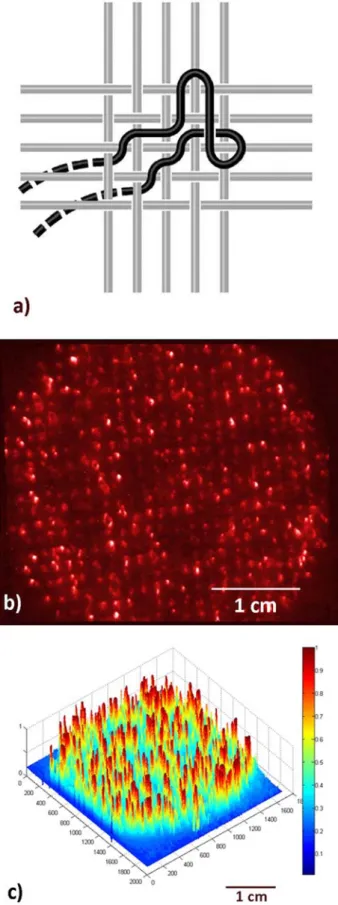
The goal of using a weaving technique is to form textile structures whilst also creating macrobending to allow side emitting of injected light. This technique was used by Cochrane et al to develop a LEF [3]. In order to improve light emission homogeneity and to correct the decrease of side emitted radiation intensity along the fiber, a specific pattern based on different satin weaves has been developed. Satin weave is one of the basic weave structures in which the filling threads are interlaced with the warp at widely separated intervals, producing the effect of an unbroken surface.
This LEF consisted of POF (250 µm, weft direction) and Polyester yarn (330 dtex, wrap direction). Since predetermined fiber macrobending leads to side emission of light, a specific pattern based on satin weave 4, satin weave 6 and satin weave 8 was elaborated to improve light emission homogeneity. The prototyped fabrics (21.5 cm × 5.0 cm: 107.5 cm²), with a density of 37 POF/cm, were weaved using hand weaving loom (ARM B60, Biglen, Switzerland).
In order to correct the decrease of side‐emitted radiation intensity along the fabric, both fibers ends were coupled to a diode laser. When the LEF was connected to a 635nm diode
laser (5W, Dilas, Germany), the fluence rate was 18.2 mW.cm‐² (i.e. 3.64 mW.cm‐² per injected W) with heterogeneity of ± 2.5 mW.cm‐² (13.7 %) at any point of the LEF. Temperature evolution as a function of time was monitored with an infrared thermal camera (A40M, FLIR, USA). It remained below 1°C for a 10 minutes illumination. At last, it was shown that the LEF was highly flexible and could easily wrap fingers without light losses. < insert figure 8> Figure 8 : a) Schematics of a woven‐based light emitting fabric (b) : Woven‐based light emitting fabric (c) : light distribution of woven ‐based Light Emitting Fabric . Homogeneous light distribution is observed
Interestingly, a woven‐based light emitting fabric can be manufactured using an adapted textile weaving loom, which enables relatively easy scale up (no size limitation for length). The technology of woven‐based light emitting fabric does not need any pre or post treatment of optical fibers because only the weaving parameters provide the diffusion of light. This fact significantly impacts on the overall cost of the product, as the cost of POF is low compared to other technologies.
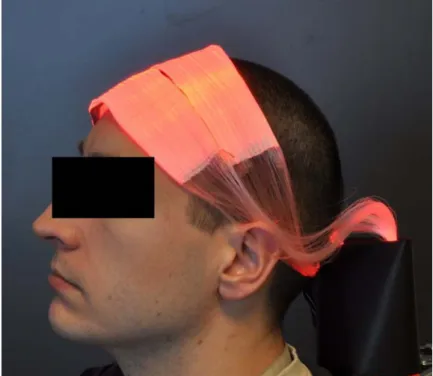
A clinical evaluation of this LEF is in progress. A phase II study, comparative, randomized, open‐label, multicenter evaluation of photodynamic therapy treatment of actinic keratoses was designed . This study aims to compare the clinical results obtained with a conventional LED system to a LEF specifically developed for this clinical application. [13, 14]. Figure 9 shows the system placed on the patient’s scalp.
< insert figure 9>
Figure 9: LEF used in a phase II study, comparative, randomized, open‐label, multicenter
evaluation of photodynamic therapy treatment of actinic keratoses
Conclusion.
The development of flexible light emitting structures remains a challenge for photodynamic therapy. Four main techniques are described in the literature: i) light blanket integrating side‐glowing optical fibers, ii) light emitting panel composed of SEOF obtained by micro‐ perforations of the cladding, iii) embroidery‐based light emitting fabric and iv) woven‐based light emitting fabric. Woven‐based light emitting fabric give the best performances: higher fluence rate, best homogeneity of light delivery, good flexibility.
References
1. Mortier, L., A phase II study evaluating the non‐inferiority of the device
FLEXITHERALIGHT compared to the conventional photodynamic therapy (PDT) L.U.H.
Department of Dermatology, Editor. 2013, ANSM, French Ministry of Health. p. 1‐66. 2. Moseley, H., Light distribution and calibration of commercial PDT LED arrays.
Photochem Photobiol Sci, 2005. 4(11): p. 911‐4.
3. Cochrane, C., et al., New design of textile light diffusers for photodynamic therapy. Mater Sci Eng C Mater Biol Appl, 2013. 33(3): p. 1170‐5.
4. Spigulis, J., et al. The "glowing" optical fibre designs and parameters. in Conference
2967 "Advanced Optical Materials and Devices". 1997. Riga: SPIE.
5. Kremenakova, D., et al., Characterization of Side Emitting Polymeric Optical Fibres. Journal of Fiber Bioengineering & Informatics, 2012. 5(4): p. 423‐431.
6. Spigulis, J. and D. Pfafrods. Clinical potential of the side‐glowing optical fibers. in
Conference 2977 "Biomedical Optics Symposium BIOS". 1997. San Jose, USA: SPIE.
7. Xu, J., et al., Photocatalytic activity on TiO2‐coated side‐glowing optical fiber reactor
under solar light. Journal of Photochemistry and Photobiology A: Chemistry 2008.
199 p. 165–169.
8. Hu, Y., K.K. Wang, and T.C. Zhu. A light blanket for intraoperative photodynamic
therapy. in Conference 7380: Photodynamic Therapy: Back to the Future 2009. San
Francisco, California, USA: SPIE.
9. Hu, Y., K.K. Wang, and T.C. Zhu. Pre‐clinic study of uniformity of light blanket for
intraoperative photodynamic therapy. in Conference 7551: Optical Methods for Tumor Treatment and Detection: Mechanisms and Techniques in Photodynamic Therapy XIX. 2010. San Francisco, California, USA: SPIE.
10. Koncar, V., Optics Fiber, Fabric Displays. Optics & Photonics News, 2005(April): p. 40‐ 44.
11. Endruweit, A., A. Long, and M. Johnson, Textile composites with integrated optical
fibres: quantification of the influence of single and multiple fibre bends on the light transmission using a Monte Carlo ray‐tracing method. Smart Mater. Struct., 2008.
17(1): p. 1‐10.
12. Selm, B., et al., Novel flexible light diffuser and irradiation properties for
photodynamic therapy. J Biomed Opt, 2007. 12(3): p. 034024.
13. Mordon, S., et al., Photodynamic therapy for the treatment of actinic keratoses: a
new device based on a light emitting fabric with fractionated illumination
in 14th Annual Congress of the European Society for Photodynamic Therapy. 2014: Nice, France.
14. Vignion, A., et al., PDT of AK using light emitting fabric and fractionated illumination in International Congress on Photodynamic Applications meeting,. 2014: Dundee, Scotland.
Table
Technology Max size (cm²) Max irradiance (mW/cm²) per injected W Homogen eity light illuminati on (%) Remarks Ref light blanket integrating side‐ glowing optical fibers 300 1.7 mW.cm‐² per injected W (8 W ‐ 633nm) ±30 % Intralipid are used to improve homogeneity No temperature elevation, but limited flexibility [9] light emitting panel with SEOF obtained by micro‐ perforations of the cladding 600 Not measured ± 500 % Never evaluated for PDT Data obtained by the authors embroidery‐based light emitting fabric 11 3.6 mW.cm‐² per injected W (1W – 652 nm) ± 40 % Temperature of 40°C obtained after 5 minutes [12] woven‐based light emitting fabric 108 3.64 mW.cm‐² per injected W (5 W ‐ 635nm) ±14% No temperature elevation LEF size can be easily increased [3]
Table 1: Characteristics of the different Light Emitting Fabrics.
Figure 1: Distal End Emitting Optical Fibers vs Side‐Emitting Optical Fibers
Figure 2: Theoretical plot of light emission along a Side‐Emitting Optical Fibers : a)
irradiating from initial end, b) irradiating from terminal end, c) irradiating from both ends.
Figure 3. Schematic diagram of a side‐glowing optical fiber (a) and its segment under irradiation (b) Particulates in in cladding layer are indicated as blacker fields in the figure [7] .
Figure 4 : (a) : picture of a blanket prototype, (b) : fiber pattern of light blanket design, (c)
light distribution of a blanket prototype (0.2% intralipid – fiber 400µm – length : 10m). Uneven light distribution is observed
Figure 5 : Side‐Emitting Optical Fibers with leakage due to micro‐perforations
Figure 6 : (a) : high magnification picture of a Light Emitting Fabric by mechanical treatment
by the projection of micro particles (Brochier Technologies, Villeurbanne, France). The micro‐perforations are clearly seen in each 500µm Plastic Optical Fiber (b) light distribution from this LEF . Uneven light distribution is observed
Figure 7 : (a) Schematics of a embroidery‐based light emitting fabric. (b) : Embroidery‐
based light emitting fabric developed by Selm et al (c) : light distribution of this embroidery‐based Light Emitting Fabric . Uneven light distribution is observed
Figure 8 : a) Schematics of a woven‐based light emitting fabric (b) : Woven‐based light emitting fabric (c) : light distribution of woven ‐based Light Emitting Fabric . Homogeneous light distribution is observed
Figure 9: LEF used in a phase II study, comparative, randomized, open‐label, multicenter
evaluation of photodynamic therapy treatment of actinic keratosis


![Figure 3. Schematic diagram of a side‐glowing optical fiber (a) and its segment under irradiation (b) Particulates in in cladding layer are indicated as blacker fields in the figure [7] .](https://thumb-eu.123doks.com/thumbv2/123doknet/14476245.523264/18.892.140.633.220.369/figure-schematic-diagram-glowing-irradiation-particulates-cladding-indicated.webp)