A Costing and Sizing Code for Highly Irradiated Normal Magnets by Joel H. Schultz
M.I.T. Plasma Fusion Center O.R.N.L. Fusion Energy Design Center M.I.T. Research Report PFC/RR-81-15
A Costing and Sizing Code for Highly Irradiated Normal Magnets by Joel H. Schultz
M.I.T. Plasma Fusion Center O.R.N.L. Fusion Energy Design Center
ABSTRACT
A sizing and costing code has been written for highly irradiated normal magnets, such as those used in accelerators and fusion reactors. Organic and inorganic insulators have been modeled. Thermal, electrical and structural sizing are included. Costing includes the magnets, as well as there associated power supplies and cooling systems. Radiation effects modeled include leakage current, heating, and increased copper resistivity due to transmutations and lattice displacements. A trade study for typical reactor parameters indicates the desirability of lightly shielded, low impedance magnet designs.
A Costing and Sizing Code for Highly Irradiated Normal Magnets by Joel H. Schultz
M.I.T. Plasma Fusion Center O.R.N.L. Fusion Energy Design Center
A.
Introduction
In. fusion reactors, employing magnetic confinement of thermonuclear plasmas, there is always a trade-off involved with nuclear shielding of the magnets. Lighter shielding allows less stored energy and less magnet current for any desired field pattern at the confined plasma, but also causes higher nuclear and gamma heating of the magnet as well as integrated damage to the magnet conductor and insulation. Because of the obvious desirability of limiting recirculating power in a fusion reactor, most designs attempt to incorporate sufficient shielding to permit operation of cryogenically cooled magnets. However, in some cases, the economies of light shielding favor magnets with normal conductors. For tokamaks, these applications include bundle divertor magnets, internal poloidal field coils, ripple trim coils, "throw-away" (Riggatron grade) toroidal field coils, and neutral beam field compensating coils. Relatively short-pulse experimental fusion reactors, such as TFTR, JET and ZEPHYR, also favor lightly shielded normal magnets.
In a heavily irradiated normal magnet, insulation integrity is usually considered to be the most limiting factor in determining magnet shielding requirements. Limitations of 109 rads for organic insulation and 1012 rads for inorganic insulations are frequently used as a basis for conceptual design, although neither design limit has much substantiation from magnet operating experience. Because of the importance of insulation selection in determining the overall magnet design, models of different insulation systems are included as an option in the code. At present, jacketed MgO conductors and unjacketed G-10 conductors are modeled. Leakage currents and temperature rises due to irradiation are modeled within the code. Lifetime radiation limits, however, are not included. Life limitations can be modeled implicitly by the specification of the exter-nal shield thickness. However, the integrated failure mechanisms, particularly for organic insulations, are not well enough characterized at this time to warrant imposing limits within the body of the code [SC80].
Another option in the code is a choice of coil shapes between circular coils and an 1-shaped saddle coil. The 1-shaped saddle coil is currently the favored shape for bundle divertors and ripple trim coils, while circular
coils are the favored shape for internal poloidal field coils.
The sizing code includes a rudimentary sizing of the magnet case structure, based on allowable pulsed stresses. Radiation effects on thermal and electrical sizing are modeled by calculating direct nuclear heating, irradiation induced leakage currents and increased conductor resisitivity from transmutation, lattice displace-ments and elevated temperature. The costing code includes the magnet, its power supply and its cooling system. Each of these is costed as a stand-alone item, and the cooling system in particular should be integrated with the overall plant cooling system in a systems sizing code.
B. Description of Method
The basic method of the code is to input the required ampere-turns in the coil, the lengths which define its perimeter and the allowable temperatures at the copper and insulation hot-spots. The conductor size and the current density in the copper are input. These are considered to be free parameters, rather than allowables, and finding good values for the conductor size and the current density are among the principal goals of this code. The code then determines the size of the coolant channel needed to reach the temperature allowables. There is never any failure to converge, no matter how small the conductor or how high the curernt density in the conductor, because the code increases the channel area at the expense of the conductor area, until the conductor current is reduced to an acceptably small quantity.
The allowable hot-spot in the insulation can be significantly higher for inorganic insulations than for G-10. Typical values for the hot-spot temperature in the insulation (C) is given by:
Thoti, = Thotoo = 150 (1)
where ThOtmgo is the hot-spot temperature in the MgO insulation (C), and
Thotins " TLotGIO=
70
(2)
when the insulation is G-10.
The hot-spot temperature in the copper (C) is given by:
where A Tj,1 is the design temperature drop across the insulation (C) The first guess at the wall temperature on the outlet side (C) is given by:
Twaliguess "Tihotcu -
30
(4)
The average temperature in the copper (C) is given by:
Ta -(Tvaguess + Ttcu) (5)
The purpose of the following iteration is to self-consistently size the conductor and the case. We already know the forces on the case, but we don't know its moment of inertia and, therefore, its thickness, until
we know the cross-section area of the conductor. Similarly, we don't know the achievable current density
in the conductor until we know the attenuation of neutron and gamma irradiation by the case. Both the case thickness and the conductor cross-section are second-order dependent on each other, so a few iterations, substituting the latest calculated values of those two parameters, should relax to a self-consistent solution in all cases. The first guess is that the cross-sectional area of the conductor package is twice the conductor copper
area. The area required by all the turns of the coil (m2
) is given by:
total 7 2.0 Ampturns (6)
Jr.'
where Ju is the current density in the copper (A/m 2), and Ampt., is the number of ampere-turns in the coil (A-T).
Equations model case thickness for the option of a constant thickness case about the magnet. The most limiting clearance affecting the toroidal ripple on axis is the*case thickness about the vertical leg closest to the plasma. Other case thicknesses are not calculated here. For modeling purposes, we are assuming that the force due to the interaction of the main toroidal field and the vertical current is dominant. The case is assumed to be rigidly supported at top and bottom. The radial force supported by the case (N) is given by:
where Veg is the height of the vertical leg of the magnet (m), and Btieg is the toroidal flux density at the vertical legs of the magnet (T). The design stress in the case (Pa) is given by:
adesign =
(9)
SMfatiguele5
where cr,,, the yield strength of the case steel (Pa), is 350 X 106 and SMftiguele5, the safety margin vs. yield strength for 105 cycles is 3.
The bendingrmo =ent applied-o the case- (N-m}) is given by:
Mcase = r- 8i (10)
We iterate a few times to solve self-consistently for the two equations for the moment of inertia of the case and the stress in the extreme fiber.
The width of the square conductor winding package (m) is given by:
Wcond = \ Acondota (12)
The overall width of the case (m) is given by:
Wase = Wcond + 2tcase (13)
The moment of inertia of the case about its vertical axis (m4
) is given by:
(W ae - W4Ol) 1
case m.12.0 -2 .0 (14)
The height of the extreme "fiber" from the neutral axis (m) is given by:
Wf
iber cfiber 2.0n t case
(15)
The bending stress in the extreme fiber of the case (Pa) is given by:
A#se Cfiber Icase
The iteration is ended with equation 19 by setting the case thickness equal to half the sum of the smallest guess that is too high and the largest guess that is too small. The case thickness (m) is given by:
(mazsmail
+
minbi,)tcase -
2.0
(19)
The neutron energy attenuation of the case
()
is given by:acase = exp-
(20)
Notice that an inverse e-folding distance of 13 cm-1 is inserted on the assumption that the case is made of stainless steel. If the shield material is stainless steel, the attenuation coefficient
()
is given by:Atten = 13 (21)
If the shield material is WTiH2 or W, the attenuation coefficient () is given by:
Atten = 11 (22)
The attenuation of any additional shielding, surrounding the case () is given by:
Qshield eXP (-At ten t~hild) (23)
where tahield is the thickness of the shield (m). The neutron fluence at the surface of the coil (n/cm2) is given by:
Fluence = .44 X 10'rPenut duty.avail years acase ashield (24)
where years is the lifetime of the magnet
(),
avail is the integrated availability of the reactor()
duty is thelocal duty factor of the reactor (), and Pall is the neutron wall-loading near the magnet (W/M2).
The atomic density of copper (atoms/cc) is given by:
6.023
x
10 X 8The e-folding distance of neutron capture in copper (cm) is given by:
efoldc, = 10.
(26)
The density of transmuted atoms in copper (atoms/cc) is given by:
Transmudens = Fluence
efdidc,
The atomic parts per million of transmuted atoms
()
is given by:Appm
=Transmuden,
X 106 AtomdensThe volumetric nuclear and gamma heating (W/m3) is given by:
(27)
(28)
(29) Nucheat = 18.8 PwaI acase ashied
Equations (34-120) are iterated to find the only self-consistent solution for the ratio of the coolant channel to the conductor height. The method is to take half the difference between a guess that is too low and a guess that is too high. The initializations of the incorrect guesses are:
amaxtow = .001
(30)
The minimum guess at aoverh that is too high () is given by:
aminhigh = 1.0
(31)
The initial guess of the ratio of coolant channel to conductor height () is given by:
(32) The flat-to-flat height of the coolant channel (m) is given by:
a
= haoverh (34)The thermal conductance of the thermal circuit (W/m-K) is given by:
G = 4 kcu 2a + .54)
((h - a)
(35)
from McAdams text on Heat Transmission [Mc64], where kca, the thermal conductivity of copper, is 350
(W/m-K).
The cross-section area of copper in the conductor ( 2) is given by:
Acu=h2 - a2
(36)
The
jacket
thickness (m) is given by:Tjck = (16 X 1.63) The insulation thickness (m) is given by:
h
Tins = . The flat-to-flat height of the jacket. (m) is given by:
(37)
(38)
(39)
Hjack =h
+
Tins+
TjackThis is 2.07 Xh/1.63 in todays conductors, where h is the flat-to-flat height of the conductor (m). The area of the conductor insulation and jacket. (m2
) is given by:
Acond = Hjack (40)
The dissipation per unit length due to nuclear heating (W/m) is given by:
Qnue = NuclietAcond (41)
Pacfac
=
(42)
AcondThe overall current density in the conductor and jacket (A/m 2) is given by:
Jcond = JcuPacfac (43)
The current density in the copper (A/m 2) is given by:
J = Jcond (44)
PaCfac The conductor current (A) is given by:
'cond = J.Acu
(45)
The area required by all the turns of the coil (m2
) is given by:
Acondtotal = Ampturns (46)
icond
If the coil shape is circular, the length of a single turn (m) is given by:
Lturn = 2.7r
Rcoi
(47)where Rcon is the coil radius for the circular coil option (m).
If the coil is an I-shaped saddle, the length of a single turn (m) is given by:
Lturn = 2 (Vieg + Hlegtar
+
Hegrad) (48)where, for the example of a bundle divertor, Hlegrad is the length of the horizontal leg in the radial direction (m), and Het.r is the length of
the
horizontal leg in the toroidal direction (m).The number of turns required
()
is given by:Nturns = Ampturtis (49)
The minimum permissible bending radius (m) is given by:
Minbend = 12 Hiack (50)
The expected displacements per neutron after annealing
()
is given by:dpn = 60 (51)
The expected lattice displacements per atom (dpa) is given by:
dpa = dpn AppmL.0 X 10-6
(52)
If the expected displacements per atom are less than 0.001, the displacements are unsaturated, and the electrical resistivity of the copper (D - m) is proportional to the irradiation.
Plattice = dpa 0.4 X 10⁸ (53)
.001
At 0.001 displacements per atom, the amount of the displacements that copper can support saturates, and resistivity due to displacements no longer increases with irradiation.
Plattice = 0.4 X 10⁸ (54)
The badness ratio of additional resistivity due to a single transmutation over that due to a single lattice displacement
()
is given by:Badta. =
3.5
(55)The Joule-Thomson coefficient -dT/dP at constant enthalpy. (C/Pa) is given by: The electrical resistivity of the copper due to transmutations of the copper into zinc and nickel (Q - m) is given by:
Badtran, Appm (.0148 X 10-8)
Piransmu = 300 (56)
Ptemp = (1.48 + .00754Ta)1. X 10~
(
The total electrical resistivity of the copper (0 - m) is given by:Peu = Pternp
+
Plattice + Ptransmu (58)The power/volume dissipated in the conductor (W/m3) is given by:
Jsquarep = U (59)
The resistance of one turn of the coil (Q) is given by:
Rturn = pcuLturn (60)
ACU
The electrical power dissipated per turn (W) is given by:
Turndisse = Lturn Acu Jquarep (61)
The electric power dissipated per coil (W) is given by:
Coildisse = Turndisse Nturns (62)
The normalized average temperature in the MgO insulation (C) is given by:
(Thotins
+
Thote)(Tnortn = 200. (63)
The thermal conductivity of MgO. (W/m-K) is given by:
kAIo =-
.7728
+ 84.835 62.696 16.23(64)
k = .To T2
+
T3"Or4 n m norm norm7The thermophysical properties of MgO are taken from Kingery,Bowen and Uhlmann [K176], The correlation is by the author. The conversion factor, scaling from the RTPR design, for a ceramic facing combined neutron
and gamma radiation from W/m2 to Gray/s (G ray/s/W/m2) is given by:
RTPRconv =
.05
(65) The maximum radiation absorption in the magnet insulation (Gray/s) is given by:Magrad = RTPReo, Pwal (66)
The electrical conductivity in ceramic insulation due to irradiation (mho/m) is given by:
CMgOrad = 5. X 10- (Magrad (67)
The correlation is based on Clinard's contribution to the LASL 1979 Special Purpose Materials Annual Progress Report [CL79].
The electrical conductivity of G-10 insulation due to irradiation is given by:
QGlOrad = 2.0 X 10¹²+ 300. X 10-12 Mag,, 6
40.0
If the insulation is MgO, the heat flux in the insulation (W/m2) is given by:
2.0 ATj. kufgo
Qin = T(71)
If the insulation is G-10, the heat flux in the insulation (W/m 2) is given by:
Qins
= 2.ATikc 10
(72)
The power density in the MgO due to leakage currents (W/m 3) is given by:
Pi, = in (73)
The current density in the MgO (A/n 2) is given by:
Jins = %/Pinsrad (74)
Eins =
0J(75) radThe ratio of peak charging voltage to steady-state voltage
()
is given by:
Vchgr =
1.4
(76)
since a ratio of 1.4 is typical of exponentially charged normal magnets.
The peak coil terminal voltage (V) is given by:
Vierm EiwTin (77)
The resistive terminal voltage at the coil (V) is given by:
Vrterm = Vterm
(78)
Vcjig,
The terminal voltage, if all the coil turns were in series (V) is given by:
Vseriea = NturnsRturnVcgrcond (79)
The number of parallel lead pairs
()
needed to achieve the design value of temperature drop in the
insulation is given by:
Npairs = series
(80)
term
rounded down to the nearest integer unless the ratio is less than one.
The power per unit length due to leakage currents (W/m) is given by:
Powi ins =
4 PinsTinslIjack
(82)
The power dissipated per single turn (W) is given by:
The power dissipated per coil (W) is given by:
Coildi . = TurndisNturns
The heat flux into the water-cooling channel (W/m 2) is given by:
Qh = Turndiss
(4
Lturna)The wetted perimeter (in) is given by:
P, = 4 a
The area of the coolant channel (m2) is given by:
A chan = a2 The hydraulic diameter (m) is given by:
Da_4 Aec"a Dh s.
The viscosity of water as a function of temperature (kg/s-rn) is given by:
Visc = 95
3600((Ti,
+
20)9(5i
+where Ti, is the inlet temperature of the coolant water (C). The mass flow rate/unit area (kg/m 2-s) is given by:
G. = PH20V where PH20, the mass density of water, is 1000 (kg/m 3).
The Reynold's number () is given by:
Re = G.DIl Visc
(84)
(85)
(86)
(87)
(88) (89)(90)
(91)
The Prandtl number () is given by:
Pr = VisC CPH2O
(92)
kH20
where
CPH20,the specific heat of water, is 4178 (J/kg-C), and
kH20,the thermal conductivity of water is 0.61
(W/m-K).
The initial guess at the wall drop Tw
0 1(C) is:
ATwan = 10 (93)
Equations (95-96) are iterated to avoid having to find an analytic solution for AT,
1 .The heat-transfer coefficient according to the Dittus-Boelter correlation as modified by Giarratano
(W/m 2-K) is given by:HGiar
=0.
2 5 91kH
Re-
Pn
T6
95)~Dha
e (Tifl+ ATw0ii)The wall drop (C) is given by:
AT..a1 = (96)
HGiar
The difference between the outlet and inlet temperature due to Joule heating (C) is given by:
ATjoute
urnis97)
(v PJ120 Achan CpH20)
The H20 temperature rise from nuclear heating of the conductor (C) is given by:
A
Ta =(98)
(VPT12OAchaniCPH20)
The water temperature rise due to insulation leakage currents (C) is given by:
Pow nsLiur rn (Vp]I20^AenCpII20)
The friction factor, good for clean steel pipe, when Re (105. ( ) is given by: The Reynold's number () is given by:
0.04
.fowRe = 0.04(Reo.-16)
(100)
The friction factor, good for Re >2000 in smooth tube ( ) is given by: The Reynold's number ( ) is given by:
125
fhighRe =
.0014 +
Re3 2(101)
The friction factor
()
is given by:if(Re >
I.e4),
f = fhighReif(Re
<
1.e4),
f = fioweThe pressure drop per unit length (Pa/m) is given by:
A = _P 2fpH20V
2
Dh The ideal pump power per unit length (W/m) is given by:
PoWpI = vAchanAP
The pressure drop per hydraulic channel (Pa) is given.by:
Pdde = pinLturn
The Joule-Thomson coefficient -dT/dP at constant enthalpy. (C/Pa) is given by:
' = ( k 2 0 FPII20CpiI20) or (102)
(103)
(104)
(105)(106)
(107)
The temperature rise due to isenthalpic expansion (C) is given by:
A Ty = Pd dt
The difference between the inlet and outlet water temperature (C) is given by:
ATjo = ATjoue + AT, + ATaue + ATin,
(109)
The temperature difference across the copper (K) is given by:
Tdiffcu=
(2.Powpii,
+
NUcheatAcond+
JsquarepAcu)G
(110)
The outlet temperature of the water (C) is given by:
T.Ut = Til + ATio
(111)
The wall temperature, calculated starting at the water inlet (C) is given by:
Twatl1120 = Tout
+
ATwajj(112)
The wall temperature, calculated starting at the insulation (C) is given by:
Ttallcu = Thatcu - Tdiffcu
(113)
If the temperature of the wall, calculated starting from the water inlet is higher than the temperature of the wall, calculated starting from the conductor hot-spot, then the coolant channel is too small. A revised guess is made of a.erh, the ratio of coolant channel height to conductor height, and equations (34-120) are repeated.
The copper wall temperature at the outlet (C) is given by:
Ttval = (TwaI-120
+
Twalcu)2.0
(117)
The average temperature in the copper (C) is given by:
Tav = (Tw
-
0Tac(118)The copper hot spot temperature with the specified water velocity (C) is given by:
Th.1 = To0
t
+
Tdiffce+
ATwaii(119)
The average temperature in the copper (C) is given by:
Tav = Thot - T2.eu
(120)
The stress in the jacket due to the water pressure. (Pa) is given by:
__
Pdelt
a
OpH2O -
(h
-a)
The pump power per coil (W) is given by:
Ppump = PowpiLturnNurns
(122)
The efficiency of the pump motors () is given by:
??pump = 0.7 (123)
The electrical power need for the pump motors (W) is given by:
Elecpurnp - lPUrP (124)
Pump
The efficiency of the bundle divertor power supply ()is. given by:
pa = 0.8 (125)
The total electrical power for the system (W) is given by:
Cilpa
Pioaln = Elecy,,,p+
Cidae(126)77ps-The overall packing factor, copper/conductor () is given by:
Pacfac
=
(127)Acond
The mass of a conductor (kg) is given by:
Meond = PmcuLiurnNurnsAcu
(128)
where pmcu, the mass density of copper, is 8900 (kg/m
3).
The mass of the case (kg) is given by:
Mcase =
4.0
pm,, Lturn tcase (WcaSe - tease)(129)
where pnss, the mass density of stainless steel, is 7800 (kg/m
3).
The mass of the magnet (kg) is given by:
Mmagnet = Mcond
+
Mcase(130)
The cost of the magnet case ($) is given by:
CoStcae =
31.3
Mc,0,
(131)
For example, the fabrication of the various TF case pieces in TFTR cost $6.7 M and the pieces weighed
670 thousand pounds. If EDIA costs for the case were proportional to hardware costs as a fraction of total
EDIA, then the EDIA charge was $1.5 M. Contingency is expected to be 10 to 20 %
.
Therefore, I estimate an
approximate total cost of $9.5 M or $31.3/kg. The cost of magnet fabrication, including winding ($) is given
by:
COStmagfab =
11.3
MAmagnet(132)
For example, fabrication of the TFTR TF coils cost $4.24 M. If EDIA was was split proportionately to
hardware cost, the EDIA cost was $1 M. Contingency was 20
%.
Since the case plus conductor for the system
weighs 1.16 million pounds, this is a specific cost of $11.3/kg. The cost of the magnet support pedestal ($) is given by:
COSt ped = 0.6 Mmagnet (133)
Although the July, 1979 ETF bundle divertor magnet was supported through the TF case, there should still be some sort of magnet pedestal, connecting the magnet to the floor. The TFTR pedestal cost $300 k and supported 1.16 million pounds- The cost of conductor insulated by MgO ($) is given by:
CostcondMgO = 15.7Mcond
(134)
This is based on a 1979 quote from Pyrotenax of Canada [HA791. The cost of G-10 insulated, internally cooled conductor is taken to be:
CostcondGO 6.94M ond (135)
For example, the TFTR TF conductor cost $1.578 M for 500,000 lb of conductor. The volt-ampere requirement of the dc power supply (W) is given by:
Ppsva = VtermNpairslcond (136)
The total cost of the magnet ($) is given by:
COStmagnet = COStcond
+
COStcase+
COStmagfab+
COStped (139) The cost of the rectifier-transformer ($) is given by:Costxj = .00125 Ppva (140)
For example, most of the TFTR transformers were purchased at $40,000 for transformer with a 2 kV x 24 kA, rectified output. However, the last four transformers cost $60,000, so the higher price is used. If the terminal voltage is greater than 1 kV, the cost of the solid-state controlled rectifier ($) is given by:
Costret = .004 Pp,,,
If the terminal voltage is less than 1 kV, the cost of the solid-state controlled rectifier ($) is given by:
COstrect = 4Npairslcond (142)
The cost of rectifiers is a controversial term, which has engendered many arguments, ever since the LASL/Westinghouse evaluation of the EPR Ohmic Heating system [HE76]. The basis for the controversy is that large controlled rectifiers have been sold to industry and the fusion program with specific costs ranging from $3/kW to $100/kW, with no apparent explanation due to economies of scale. Most studies have
as-sumed specific costs of about $30/kW, which eliminates the use of solid-state switches for ohmic heating circuits and makes ohmic heating power supplies the dominant cost item for the whole reactor, when the aspect ratio is made too small. However, I advocate the more optimistic specific cost of $4/kW for relatively low voltage supplies. All of the large 1,000 V supplies procured by the fusion program cost in the range of
$4/kW, including the TF supplies for Alcator C and Ormak and the PF and TF modules for TFTR. The cost of buswork, one magnet ($) is given by:
COstbu, = 50.0 Npair, 'cnad (143)
The total cost of the power supply ($) is given by:
Costp, = Cost b..
+
Costzjm,+
Costrect (144)The cost of the water pump ($) is given by:
CostH20pump =
.007
Coili..(145)
The cost of the water purifier ($) is given by:
COstpuif =
.0015
Coildi .(146)
The cost of the heat exchanger ($) is given by:
Costh, =
.004
Coild,, (147)The cost of water piping, assumed to be SS-316, 2 cm OD ($) is given by:
COStH20pipe = 100.0 Busrun (148)
where Bus,,, is the bus length from the magnet to the power supply (m).
Cooling system costs are taken from schedule 22.03.02 of the fusion reactor standard costing document [SC79]. The cost of the water cooling system ($) is given by:
Costcooi = COStH20pump
+
COStpurif+
COSth,+
COStH20pipe (149) The total cost of the bundle divertor magnet system ($) is given by:COStbdmagsys = Costps
+
COstmagnet+
Costcool(150)
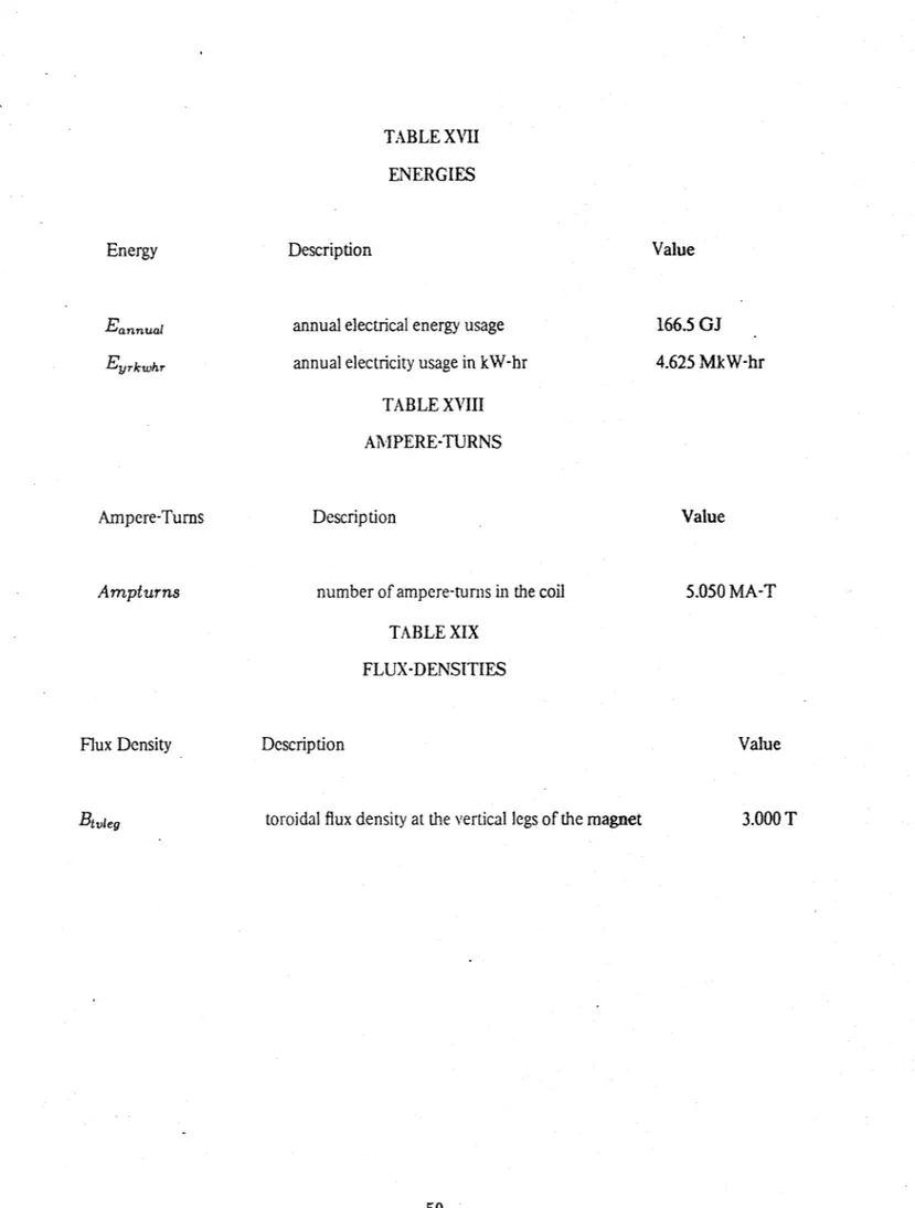
The annual on-time of the magnet (s) is given by:ton,a nnual = duty avail X 3600 X 24 x 365 (151) The annual electrical energy usage (J) is given by:
Eannual = Ptotal ton,annual
(152)
The annual electricity usage in kW-hr (kW-hr) is given by:
Eyr,kh, = -Eannua
3.6 x 10⁶
(153)The annual cost of electricity ($) is given by:
C. Results
Of all the fusion applications which might require high magnet irradiation, the bundle divertor appears to benefit the most from the elimination of shielding, because of the high order dependence of magnetic field ripple enhanced transport on the magnetic moment of the divertor magnet. The use of ceramic insulation to reduced shielding requirements has been considered previously by Schultz [SC80. Typical magnet require-ments for an INTOR or ETF scale bundle divertor magnet in a four magnet system might be 5 million ampere-turns, 4 tesla toroidal field at the front vertical leg and front leg heights and lengths of 1.2 m. Keeping allowable stresses and temperatures fixed, we examined the effect of varying conductor size, copper current density, shield thickness, and the allowable temperature rise in the insulation. In order to look at the overall tradeoff of current density, recirculating power and system code, we assumed that a current density over the envelope of 2 kA/cm2, a recirculating power of 25 MW in one front magnet and a cost of 25 M$ were
each equally intolerable and adopted the sum of the ratioes of the actual design values to those three "equal badness" values as a normalized overall cost figure.
As seen in figure 1, the overall economics of the system appear to improve as water velocity is increased in the range of 2 to 15 m/s, While the cost of the system is increased by increased water velocity, due to increased water pump costs and increased recirculating power to drive the pumps, the overall conductor current density increases by 50 % , as the water velocity is increased from 2 to 16 m/s. However, lifetime limitations caused
by magnet erosion and vibration have not been modeled. Since improvements in magnet performance are very small in the velocity range of 7 to 15 m/s, we selected 7 m/s as the reference velocity.
For a water velocity of 7 m/s, the optimum conductor size is about 5 cm, as shown in Figure 2. In fact, the optimum is broad between 5 and 10 cm. Since this size range is somewhat beyond the limits of what is now commercially available, a value at the low end of the optimum size range was selected. Unlike my previous study [SC80], which suggested that many electrically parallel turns should be employed (as well as hydrauli-cally paralleling every turn), in order to avoid thermal runaway with reasonably small conductors, this trade study suggests that it is better to use larger conductors that.avoid the need for paralleling. This is apparently caused by the relatively high heat removal and thus high pumping and electric power requirements of the water pumping system, which are a nontrivial fraction both of total system cost and recirculating power. Since pump power increases with the cube of the water velocity, these costs are reduced when larger conductors are
used, instead of paralleling.
Up to a flat-to-flat height of 4 cm, the current density over the envelope of the magnet and its case improves, as the increased temperatue drop in the copper is more than balanced by the improved cooling effectiveness of the larger cooling channels. Above 4 cm, there is no significant improvement. The total electrical power also declines as the flat-to-flat height increases because of the decrease in pumping power, but the improvement is not significant over a broad range of conductor sizes. The total cost of the bundle divertor magnet system has a minimum at a conductor heightof 4.2 cm. This minimum is-fairly sharp, since above 4.2 cm, bus and power supply costs increase linearly with current (or with the square of the height), and these are dominant costs of the whole system, as shown in Figure 3. The sharp downward transitions in cost represent decision points, where the number of parallel electrical connections is reduced by one and there is a quantum drop in the bus and power supply costs.
With a coolant velocity of 7 m/s and a flat-to-flat height of the conductor of 5 cm, an insulation tempera-ture drop of about 5 C is about optimum, as shown in figure 4. A higher temperatempera-ture leads to a significant fraction of the total power dissipation in the conductor being caused by leakage currents in the insulation. Because the insulation is thin and has a relatively large surface area, being on the outside of the conductor, a proportionally large amount of power can be dissipated without a very large change in the temperature drop across the insulation. This justifies the code's use of average values of temperature dependent physical properties, such as thermal conductivity. As shown in figure 4, once it is possible to use a single pair of leads at ATi,8 above 4 C, there is no advantage to allowing the temperature across the insulation to increase
further. As shown in Figure 5, the cost trade-off is totally dominated by the high bus currents needed to achieve a very low temperature drop across the insulation. Once the number of parallel leads has been reduced to a single pair, further increasing the temperature drop just increases the thermal load on the system, with concomitant increases in the cost of the water cooling system, as shown in Figure 5. Another reason favoring the selection of a lower temperature drop is the lower terminal voltage, as shown in Figure 5. Although low voltage per se does not save any money, the high degree of uncertainty about the breakdown behaviour of highly irradiated magnets favors designs with low enough voltages that it may be difficult to sustain an arc under any circumstances (<< 1, 000 V). At a temperature drop of 4 C, the terminal voltage is 300 V, which is not guaranteed safe, but is less risky than the 700 V corresponding to a drop of 20 C.
The most controversial and significant conclusion of the trade study is shown in figure 6. In this study, copper current density and conductor size were held constant, while the shield thickness was decreased. Despite insulation leakage, increased copper resistivity due to lattice displacements and transmutations and increased neutron and gamma heating of the conductor, there is an obvious improvement in the overall "goodness" of the bundle divertor, down to zero shielding. The overall current density over the envelope im-proves by more than a factor of three as the shield is decreased from 30 cm to nothing more than the structural case, and it cannot be improved that much by any other parameter, such as increasing the currrent density in the copper, as shown in Figure 8. The total electrical power for the system actually declines a little bit with
decreased shielding. Presumably the increased nuclear and gamma heating opens up the coolant channels, in order to maintain constant allowable temperatures, and the decrease in pump power slightly outweighs the
increase in Joule heating. As shown in Figure 7, this same effect also leads to counterintuitive increases in the costs of the power supply and the magnet, as the shielding is increased. The cost of the power supply increases by 15 % and the cost of the magnet by 6 % as the shield thickness increases from 0 to 30 cm.
Reducing the shielding is the only parameter change that causes a dramatic improvement in system per-formance. This conclusion has perhaps been obvious to plasma designers [H1801 for some time, but is certainly not obvious to magnet designers. We will explore a magnet design in the region of overall optimum goodnesss in more detail, in order to gain more insight about the validity of the conclusion that all shielding other than that provided by the magnet case should be eliminated.
With conductor size fixed, the most desirable value of the current density in the copper is shown to be approximately 2 kA/cm2
, as shown in figure 8. Higher current density decreases ripple, while increasing recirculating power. Because of the need for a case and a shield, the overall current density over the magnet envelope does not increase nearly as rapidly as the current density of the copper. For example, with a 20 cm shield, as the copper current density increases a factor of ten from 5 to 50 MA/m2, the envelope current
density only increases by a factor of 3. However, with no shield other the the structural case, the current density over the envelope increases by a factor of 5 from 3 MA/m2 to 15 MA/m 2, over the same range of
copper current density. The recirculating power is also a first-order function of the current density in the copper and increases from 8 MW to 65 MW in a single coil, over the same range. The system cost showns an optimum at about 1.5 kA/cm2, but it is not as important a factor as the current density and the recirculating
power. Even with a copper current density of 5 kA/cm2, the divertor system cost is only 11.5 M$ for a front
coil. The power supply is only 2 million dollars at the optimum current density of 2 kA/cm2 in the copper,
as shown in the Figure 9. Again the paradoxical result that the cost of the coolant system declines at higher current densities is seen in Figure 9, again probably a function of the larger coolant channels.
D.
Worked Example with Low Overall Cost Figure
We look at an example with a low cost figure in Tables I through XXIX. The overall coil dimensions are shown 'in Figure 10. In this example, the inputs include a conductor copper height of 5 cm, a water velocity of 7 m/s, current density in the copper of 1.38 kA/cm2
and a temperature drop across the insulation of 5 C. There is no shield, other than the structural case. The structural case is 4.4 cm thick and provides slightly less than a factor of 2 attenuation of the neutron and gamma flux. These dimensions give an overall conductor current density of 1.38 kA/cm2
and a current density over the coil envelope, including the case, of 1.1 kA/cm2. The case must be considerably thicker on the top and bottom than around the vertical leg.
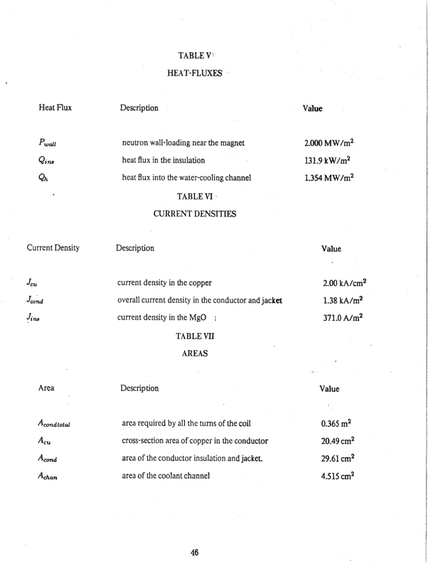
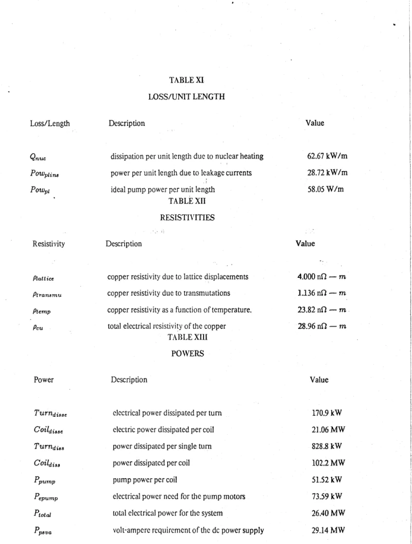
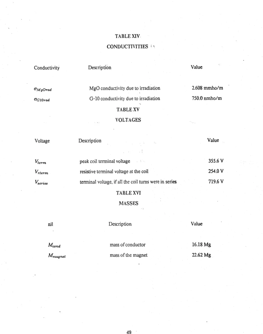
B3ecause of the high coil irradiation, the code selected a low impedance design. Two parallel conductors carry 41 kA apiece, while the peak voltage during charging is only 356 V, with a peak resistive voltage of 254 V. Despite the low impedance and the limitation of the temperature rise in the insulation, the power dissipation density in the MgO is 53 MW/m3 vs. 21 MW/m3
due to nuclear and gamma heating and only 11.6 MW/m3
due to Joule heating. The electric field in the insulation is 1.42 X 10⁵ V/m, or 3 V/mil, which would represent a conservative design in an unirradiated environment.
The conductor dimensions are shown in Figure 11. The 5.44 cm flat-to-flat dimension of the outer jacket is larger than any conductor manufactured by Pyrotenax of Canada with MgO insulation, but does not represent any significant extrapolation in copper conductor technology as such, being smaller than any of the three toroidal field coil conductors in the next generation of tokamaks, TFTR, JET and JT-60. With the manufacturer's recommendation that the radius of curvature should be no smaller than 12 times the flat-to-flat height, the radius of curvature would be restricted to 60 cm, which would leave the 1.2 m long legs rather more circular than square. However, in the field at Los Alamos, the larger conductors are routinely bent to 6 times the flat-to-flat height, so hopefully the conductor could be bent to 30 cm or better, if desired.
sleeve may be necessary between the water and the copper to prevent rapid erosion of the copper by radiolysis products. Steel cladding of thinness down to 1 mil is routinely used in the nuclear industry [SC811, and may be useful here without serious degradation of heat removal or achievable bending radius.
The inventory of temperature drops through the system is shown in Table I1. The water inlet tempera-ture is 25 C. It rises 13 C due to Joule heating, 34 C due to nuclear heating and 16 C due to leakage currents in the insulation, giving an outlet temperature of 88 C, which will require a modest amount of pressurization to avoid any cavitation. These temperature rises, are achieved with a Reynold's number of 184,000, a heat flux into the water channel of 135 W/cm2
and a pressure drop of 1.3 atmosphere. The temperature rise across the copper at the hot outlet end is 57 C, giving a copper hot-spot temperature of 145 C, 5 C below the manufacturer's recommendation. The rise of 5 C across the insulation brings the system hot-spot tem-perature to 150 C. This is considerably higher than the insulation hot-spot temtem-perature of 70 C permitted with G-10 insulation. The resistivity of the copper has risen from the nominal room temperature value of 1.67 x 10⁻⁸f - m to 2.9 X 10~80 - m. Two-thirds of the rise is due to the elevated temperature and the
rest due to lattice displacements. Transmutations add only a little, because of the low integrated duty factor of the FED application.
The electrical dissipation of a single coil is 24 MW, while the total electrical and thermal dissipation is 102 MW. With the addition of the electrical power needed for the cooling system, the system recirculating electrical power is 26.4 MW. Since the rear coils of the bundle divertor can have a considerably lower current density than the front coils, without adversely affecting the toroidal ripple, the coil system recirculating power should be significantly more than 50 MW, but significantly less than 100 MW. Because of the low duty factor of FED, the additional annual cost of electricity should only be $278 K.
The largest and dominant component of the magnet system cost is electrical buswork, costing $4 M. The total cost of the electrical power supplies is only $4.46 M, using the low cost of rectifiers, justified above. The cooling system is costed at $1.3 M, while the magnet, despite its comparatively expensive conductor, is only $725 K. This implies a total cost of the four magnet system somewhere in the neighbourhood of $15 M.
The use of optimization techniques, using weighted cost figures or figures of merit, generally has no justification in real designs. However, in this case, the technique seems to have selected a reasonably sensible design. Having examined the "optimum" design, I would opt for an even lower impedance design. If we
doubled the parallel current, the cost of the bus and power supply would increase by about $10 M, but the heat generated by leakage currents would decrease markedly. What is more important, designing in the face of uncertainty, we would be much closer to achieving a conservative design. If dielectric breakdown were now to occur, it would have to occur with only 150 V to sustain an arc and only 1.5 V/mil to drive leakage currents.
The principle reason for using MgO insulation in FED is in order to some possibility of a conservative design for a reasonable service life. While there are currently uncertainties with all candidate technologies, I believe that the development of a larger MgO insulated conductor and the characterization of leakage current in MgO under neutron and gamma irradation represents an RDAC program of moderate cost and duration, while the debates over the lifetime of organic insulation will never be resolved without considerable field experience. Over the short run, organic insulations, such as G-10, will always outperform MgO with any shielding thickness, because they have much less leakage current under irradiation and they have good mechanical properties without the need for a jacket. It is only with a high integrated fluence that the superior parametric stability of the MgO insulation dominates. Therefore, I believe that the low electric field design approach is the most consistent with this conservative philosophy. If one is willing to take risks with either the ripple in the plasma or the life of the insulation, then an organic insulation with a normal or superconducting conductor should be selected.
E.
Conclusions
* A self-consistent code has been developed which can be a powerful tool in the design and analysis of
highly-irradiated copper magnets.* The overall performance of a bundle divertor magnet can be improved by eliminating the shielding, without imposing severe lifetime limitations on the magnet.
* For a typical bundle divertor, application the optimum current density in the copper is about 2
kA/cn2
.
* Designing with a low electric field across MgO insulation is a conservative approach to near-term magnet design under intense irradiation.
Acknowledgments
References
[CL79] F.W. Clinard, Los Alamos Scientific Laboratory, 1979 Special Purpose Materials Annual Progress Report
[HA79] W.E. Hanthorn, private communication
[HE76] F.M. Heck, E.I. King and R.E. Stillwagon, "Experimental Power Reactor Ohmic Heating Energy Storage Study",Westinghouse Fusion Power Systems Report WFPS-TME-038, Nov 1976
[K176] Kingery, Bowen and Uhlmann, "Introduction to Ceramics," Wiley-Interscience, 1976 [Mc64] R. McAdams, "Heat Transmission," 1964
[SC79] S.C. Schulte et al,"Fusion Reactor Design Studies -Standard Unit Costs and Cost Scaling Rules," Battelle Pacific Northwest Laboratory PNL-2987 Sept 1979
[SC80] J.H. Schultz, "Sizing of the Thermal and Electrical Systems for an FED Bundle Divertor Design with MgO Insulation," M.I.T. Plasma Fusion Center Research Report PFC/RR-80-28, Dec 1980
INPUT VARIABLES
Parameter Description Units
Amptur, number of ampere-turns in the coil (A-T)
Btvieg toroidal flux density at the vertical legs of the magnet (T)
Busrun bus length from the magnet to the power supply (m)
ATi , design temperature drop across the insulation (C)
GlO is G-10 insulation
()
Alegrad length of the horizontal leg in the radial direction (i) Hiegtor length of the horizontal leg in the toroidal direction (m)
J. current density in the copper (A/m 2)
MgO is MgO insulation
()
Pwall neutron wall-loading near the magnet (W/M2
)
Rco; coil radius for the circular coil option (M)
ThOtG1O hot-spot temperature in G-10 insulation (C)
ThotMgo hot-spot temperature in the MgO insulation (C)
Ti. inlet temperature of the coolant water (C)
Vjeq height of the vertical leg of the magnet (M)
avail integrated availability of the reactor
()
INPUT VARIABLES -Continued
Parameter Description Units
duty local duty factor of the reactor
()
h flat-to-flat height of the conductor (M)
insulation specifies the insulation technology selected
()
1-coil is an 1-shaped coil (plan view)
shape specifies the shape of the magnet
()
shield shield material
()
tshield thickness of the shield (M)
v velocity of the coolant water (m/s)
ASSIGNED VARIABLES Parameter A0 0.d A cond Acondiotal ACeu Appm Atomdens Atten Badtrans Coilad,, COildise COStH2opipe COStH2Opump COstbdmagsys Costbs, Costcase Costcond CostcondGIo Description
area of the coolant channel
area of the conductor insulation and jacket. area required by all the turns of the coil cross-section area of copper in the conductor atomic parts per million of transmuted atoms atomic density of copper
shield material attenuation coefficient
resistivity badness ratio of transmutation vs lattice displacement power dissipated per coil
electric power dissipated per coil
cost of water piping, assumed to be SS-316, 2 cm OD cost of the water pump
total cost of the bundle divertor magnet system cost of buswork, one magnet
cost of the magnet case cost of the conductor
cost of conductor insulated by G-10
Units
(m2) (m2) (m2)(m2)
() (atoms/cc)()
()
(W)
(W)
($)
($)
($)
($)
($)
($)
($)
ASSIGNED VARIABLES -Continued Parameter COStcondMgO Costcool COStelecyr CoSthx Costmagfab Costmagnet Cost ped Costp. Costpurif Costrect Costzfmr CPH20 'AAr ATvaLL ATin,
A Tio
A
TjOWFe A T, Descriptioncost of conductor insulated by MgO cost of the water cooling system annual cost of electricity cost of the heat exchanger
cost of magnet fabrication, including winding total cost of the magnet
cost of the magnet support pedestal total cost of the power supply cost of the water purifier
cost of the solid-state controlled rectifier cost of the rectifier-transformer
specific heat of water
pressure drop per unit length wall drop
water temperature rise due to MgO leakage currents difference between the inlet and outlet water temperature.
difference between the outlet and inlet temperature due to Joule heating. temperature rise due to isenthalpic expansion.
Units
($)
($)
($)
($)
($)
($)
($)
($) ($) ($)($)
(J/kg-C)
(Pa/m)
(C) (C)(K)
(C)
(K)
ASSIGNED VARIABLES -Continued
Parameter Description Units
AT. H20 temperature rise from nuclear heating of the conductor (C)
Dh hydraulic diameter (m)
E.nnual annual electrical energy usage (J)
Ein, electric field in the MgO (V/m)
Elecpump electrical power need for the pump motors (W)
Eyr,kwhr
annual electricity usage in kW-hr
(kW-hr)
Fluence neutron fluence at the surface of the coil (n/cm2)
Frcase radial force supported by the case (N)
G thermal conductance of the thermal circuit (-W/m-K)
Gm mass flow rate/unit area (kg/m 2-s)
HGfar Giarratano's heat-transfer coefficient (W/m2-K)
Hack flat-to-flat height of the
jacket.
(m)case moment of inertia of the case about its vertical axis (M4 )
1cond conductor current (A)
Jond overall current density in the conductor and jacket (A/m 2)
JC. current density in the copper (A/M 2
)
Ji, current density in the
MgO
(A/M 2)ASSIGNED VARIABLES -Continued
Parameter Description Units
Ltury, length of a single turn (i)
Magrad maximum radiation absorption in the magnet insulation (Gray/s)
MIcase bending moment applied to the case (N-m)
Mcond mass of a conductor (kg)
Minbcnd minimum permissible bending radius (M)
Mmagnet mass of the magnet (kg)
Npair number of parallel lead pairs
()
Nturns
number of turns required
()
Nucheat volumetric nuclear and gamma heating (W/M3)
ton,annual annual on-time of the magnet (s)
Pacfac overall packing factor, copper/conductor
()
Pdelt pressure drop per hydraulic channel (Pa)
Pi n power density in the MgO due to leakage currents (W/m 3)
PowP, ideal pump power per unit length (W/m)
Powplins power per unit length due to leakage currents (W/m)
Ppsva volt-ampere requirement of the dc power supply (W)
Ppump pump power per coil (W)
ASSIGNED VARIABLES -Continued Parameter P. Qh
Qin.
Qn.e RTPRcon, Re Rturn SMfatiguele5 UGIOrad UMgOrad EpH2O Crad Tav Td iffcu Thoi Thot u Thotin Ti n, Description wetted perimeterheat flux into the water-cooling channel heat flux in the insulation
dissipation per unit length due to nuclear heating conversion factor from W/m 2 to Gray/s.
Reynold's number
resistance of one turn of the coil
safety margin vs. yield strength for 105 cycles electrical conductivity of G-10 due to irradiation
electrical conductitivity in ceramic insulation due to irradiation stress in the jacket due to the water pressure.
insulator electrical conductivity due to irradiation average temperature in the copper
temperature difference across the copper
copper hot spot temperature with the specified water velocity hot-spot temperature in the copper
hot-spot temperature in the insulation insulation thickness Units (M) (W/m2) (W/m2) (W/m) (Gray/s/W/m 2)
()
(fl)
()
(mho/m) (mho/m) (Pa) (mho/m) (C) (K) (C) (C) (C) (M)ASSIGNED VARIABLES -Continued Parameter Tjack Ptotal Transmuden, Turni,, Turndisse Twai TwaILH2O Twaiceu Twaiiguess Vchg,. Visc Vrterm Vlerie8 Vierm Wcse Description jacket thickness
normalized average temperature in the MgO insulation total electrical power for the system
outlet temperature of the water density of transmuted atoms in copper power dissipated per single turn
electrical power dissipated per turn copper wall temperature at the outlet
wall temperature, calculated starting at the water inlet wall temperature, calculated starting at the insulation first guess at the wall temperature, outlet side
ratio of peak charging voltage to steady-state voltage viscosity of water as a function of temperature resistive terminal voltage at the coil
terminal voltage, if all the coil turns were in series peak coil terminal voltage
overall width of the case
width of the square conductor winding package
Units (W) (C) (W) (C) (atoms/cc)
(WV)
(WV)
(C) (C) (C) (C)()
(kg/s-m)(V)
(V)
(V) (in) (in)ASSIGNED VARIABLES -Continued
Parameter Description Units
a flat-to-flat height of the coolant channel (m)
acase neutron energy attenuation of the case
()
ashield attenuation of any additional shielding, surrounding the case
()
amaziow maximum guess at aoverh that is too low
()
aminhigh
minimum guess at aoverh
that is too high
()
aoverh ratio of coolant channel to conductor height
()
Cfiber height of the extreme "fiber" from the neutral axis (M)dpa expected lattice displacements per atom (dpa)
dpn expected displacements per neutron after annealing
()
efoldc. efolding distance of neutron capture in copper (cm)
rips efficiency of the bundle divertor power supply
()
7pump efficiency of the pump motors
()
f friction factor
()
.highRe friction factor, good for Re >2000 in smooth tube
()
.lowRe friction factor, good for clean steel pipe, when Re (105.()
k-u thermal conductivity of copper (W/m-K)
kGIo thermal conducitivity of G-10 (W/m-K)
ASSIGNED VARIABLES -Continued
Parameter Description Units
kMgo thermal conductivity of MgO. (W/m-K)
A Joule-Thomson coefficient -dT/dP at constant enthalpy. (C/Pa)
PI120 mass density of water (kg/M 3)
PCu total electrical resistivity of the copper (0 - m)
Plattice, electrical resistivity of the copper ( -m)
PMCu mass density of copper (kg/m 3)
PM, mass density of stainless steel (kg/m 3)
Ptemp electrical resistivity of copper as a function of temperature. (f - m)
Ptransmu electrical resistivity of the copper due to transmutations -( - m)
yield strength of the case steel (Pa)
Cbend bending stress in the extreme fiber of the case (Pa)
adesign design stress in the case (Pa)
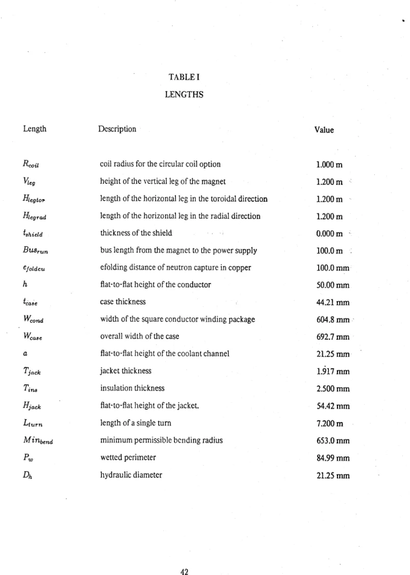
TABLE I LENGTHS
Length Description Value
Rcoi, coil radius for the circular coil option 1.000 m
Vleg height of the vertical leg of the magnet 1.200 m
Hegto,, length of the horizontal leg in the toroidal direction 1.200 m Hegrad length of the horizontal leg in the radial direction 1.200 mn
tshield
thickness of the shield
0.000 m
BUSrun bus length from the magnet to the power supply 100.0 m
efoldcu efolding distance of neutron capture in copper 100.0 mm
h flat-to-flat height of the conductor 50.00 mm
ease case thickness 44.21 mm
We0nd width of the square conductor winding package 604.8 mm
Wcase overall width of the
case
692.7 mma flat-to-flat height of the coolant channel 21.25 mm
Tiack
jacket
thickness 1.917 mmTi. insulation thickness 2.500 mm
Hiack flat-to-flat height of the jacket. 54.42 mm
Lturn
length of a single turn
7.200 m
Minbend
minimum permissible bending radius
653.0 mm
P. wetted perimeter 84.99 mm