Publisher’s version / Version de l'éditeur:
Vous avez des questions? Nous pouvons vous aider. Pour communiquer directement avec un auteur, consultez la
première page de la revue dans laquelle son article a été publié afin de trouver ses coordonnées. Si vous n’arrivez pas à les repérer, communiquez avec nous à PublicationsArchive-ArchivesPublications@nrc-cnrc.gc.ca.
Questions? Contact the NRC Publications Archive team at
PublicationsArchive-ArchivesPublications@nrc-cnrc.gc.ca. If you wish to email the authors directly, please see the first page of the publication for their contact information.
https://publications-cnrc.canada.ca/fra/droits
L’accès à ce site Web et l’utilisation de son contenu sont assujettis aux conditions présentées dans le site LISEZ CES CONDITIONS ATTENTIVEMENT AVANT D’UTILISER CE SITE WEB.
Technical Memorandum (National Research Council of Canada. Division of
Building Research); no. DBR-TM-13, 1948-12-13
READ THESE TERMS AND CONDITIONS CAREFULLY BEFORE USING THIS WEBSITE. https://nrc-publications.canada.ca/eng/copyright
NRC Publications Archive Record / Notice des Archives des publications du CNRC : https://nrc-publications.canada.ca/eng/view/object/?id=8ff2d597-6540-441a-ae85-73ddcb92cfae https://publications-cnrc.canada.ca/fra/voir/objet/?id=8ff2d597-6540-441a-ae85-73ddcb92cfae
NRC Publications Archive
Archives des publications du CNRC
Access and use of this website and the material on it are subject to the Terms and Conditions set forth at
NATIONAL RESEARCH CCT"';NCIL OF CAI\ADA
ASSOC1A'rE COlVlN1I'l1TEE ON SOIL AND SNOW MECHANICS
TECHNICAL MEMORANDUM NO.
13
CANADIAN PAPERS: ROTTERDAM SOIL MECHANICS CONF1ERENCE, 1948
Ottawa
June,
1949-The Second International Conference on Soil Mechanics
and Foundat ion Engineering was held in Ro
t ter-d
am;HoLLand ,
from 21 to 30 June 9 1948
0The fir st such conference w as
held in 1936 as a part of the tercentenary celebrations of
Harvard University, Cambridge, Masso
'I'Iie incidence of war
necessitated the gap of twelve years between the meetings
but it is now hoped to convene future conferences at
intervals of not more than four yearso
Seven Canadians were present at the Harvard meetings
oDespite the distance from Ca n ada ,
the Ro
t t er-damConference
was attended by five Canadians 9 Dean Ro Mo Hardy of the
University of Alberta acting as leader of the Canadian
ァイッオーセ
The Associate Committee on Soil and Snow Mechanics
of the National Research Council is pleased to publish
these reprints of the seven Canadian pap ers which were
presented to the Rotterdam meetings 9 and which are
in-cluded in the of fic
ialProceedings
0Since the end of the war
9one of the continuing
activities of the Associate Committee has been to assist
in fostering Soil Mechanics in Canadao
AccordinglY9
the
Committee followed with interest the arrangements for the
revival of international
セッー・イ。エゥッョin this field and
was glad to be able to as s
is
t ,financially and otherwise,
in ensuring that Canada was well represented at Rotterdamo
A Civilian Suil Mechanics SubcoffiL'11ittee has been
appointed by the Associate
cッセョゥエエ・・[it consists of
regional representatives in the Maritimes 9 Montrea1
9Ottawa
9Toronto,
the Prairies and British Columbiao
The
sオ「セcommittee has now been designated as the Canadian
p。イエゥ」ゥセpating group in the International Society of Soil Mechanics
an d F'oundation Engineering which was formed at the Rotterdam
Conference
0The principal function of this Subcommittee is
to assist in the further development and application of
Soil Mechanics throughout Canada"
Inquiries with regard
to its work will be welcome; they may be addressed to
NIl' 0F" Lionel Peckover, SecretarY9 Associate Committee on Soil
and Snow MechanicB 9 National Research
Council, Ottawao
Ottawa;
6th June 9 1949
Robert F. Legget
Chairman
Photographic Method cf Determining the Sell
Action Beneath Footings ••....• , ..••••••••••.••.•••• M. G. Bekker
Foundation Conditions
in the Edmonton Area ....•.••••
R. M. Hardy
Engineering in Permafrost in Canada's
Mackenzie Valley ••..••••..••••••.•••••.••••••••• H. A o Hemstock
Notes on Some Canadian ItSiltslloo •• Ho F. Legget and
F",L. Peckover
Soil Mecr.anics in Canada ••• o••••••••••
0 • • • • • • • • • • 0 'o.
R. F. Legget
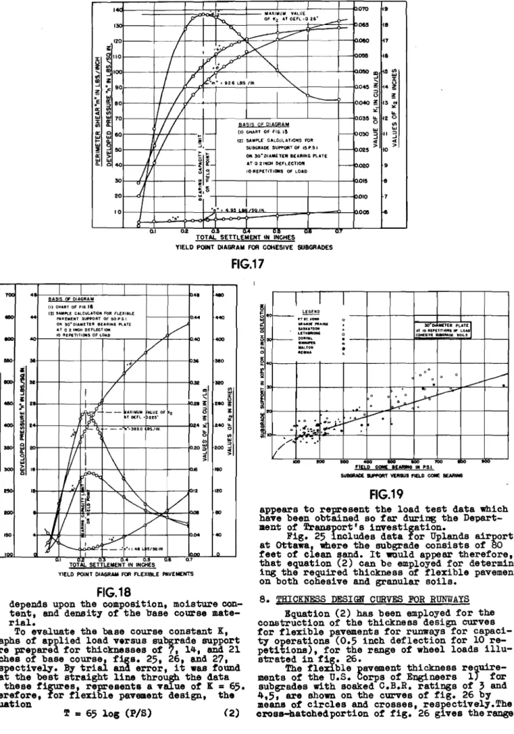
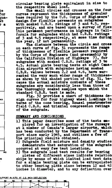
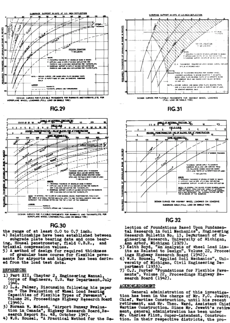
An Investigation of Airport Runways in Cvnada •••••••• N. W. McLeod
The Stability of Granular and Cohesive Materials ••••• N. W. McLeod
PHOTOGRAPHIC METHOD OF DETERMINING THE
SOIL ACTION BENEATH FOOTINGS
by
M. G. BEKKER
Associate Committee on Soil and Snow Mechanics
National Research Council of Canada
REPRINT OF THE PROCEEDINGS OF THE SECOND INTERNATIONAL
PHOTOGRAPHIC METHOD OF DETERMINING THE SOIL ACTION BENEATH FOOTINGS
.M.G. BEKKER
Associate Committee on Soil and Snow Mechanics, National Research Council of Canada.
1. ABSTRACT
A footing when forced into the ground. which has some internal friction, builds up a prismatic soil body, permanently attached to
the footing base, if friction and adhesion be-tween soil and the base are suffictently large.
Since the shape of this body directly
af-fects the bearing capacity of the footing, a photographic method has been devised which en-ables one to photograph the body in question.
The improvement of this method by intro-ducing motion pictures may help in the elucid-ation of many practical problems.
this computed under the above assumption. In accordance to the general theory as quoted above, this might have been explained by the fact that the slope angle was higher thanCfI,.
In order to check this explanation direct-ly, the following method was used. A camera (fig. 2) was rigidly attached to the extension of a footing and secured to a solid base. The footing was located behind the glass plate of the sand box. The latter subsequently was lift-ed up by means of a hydraulic jack. During the upward motion of the sand box pictures were セ
ode. PUMP JACK ( SAND BOX FOOTING GLASS PL"TE
FIG.2
FIG.3
..
2. DESCRIPTION OF THE mセhodIf a continuous footing with a rough base is loaded, then the friction and adhesion be-tween the soil and the footing is responsible for the formation of a triangular prism of soil as shown in fig. 1.
This prism is in a permanent state of elastic equilibrium and makes a footing exten-sion which practically remains unchanged.
Assuming that radial shear takes place on both sides of the prism (fig. 1) and admitting that potential surfaces of sliding intersect each other at an angle of 90 MセL the slope of the prism walls as measured with reference to the footing base should be til ted at any angle enclosed between セ and 45 +セORエ provided that the friction and adhesion between the soil and the base is sufficiently high.
ZONE 012 I2ADIAL
SHEAI2.
FIG.1
According to TERZAGHI, 1) whose opinion was stated above, trial computations have shown that the angle of base friction, requir-ed to produce the state of plastic flow illus-trated in fig. 1, is very much smaller than the angle of shearing resistance of the sup-porting soil. This enables one to assume that the slope of the prism wall always rises at セ
angle to the horizontal.
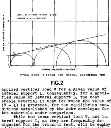
The method of determining bearing capaci1:iY of soil as discussed further by TERZAGHI was exemplified by computing bearing capacity factors N9 Nq and NI on the assumption of the slope angle セアオ。ャ cp. •
During the performance of actual tests with a cohesionless sand (cp • 350 ) , it appear-ed that a wooden footing with a smooth base supports almost twice as much of a load than
One of them is shown in fig. セN This pic-ture definitely shows the shape of the pris-matic soil body rigidly attached to the base of the footing and indicates that the slope angle is close to 600 • Computations of N coef-ficient as performed for this angle gavefthe results in a complete agreement with those measured.
It is being contemplated to apply this method to the closer investigation of problems discussed by DINGLINGER 2), ZIMMERMANN 3),
and RATHJE 4) in conjunction with the forma-tion of a soil body under the acforma-tion of piles, blades etc.
It also is expected that improved equip-ment with 8 motion picture camera may throw
some more light on the transition of soil from the state of elastic to the state of plastic equilibrium as considered by FROHLICH
5).
セN CONCLUSIONS
1) Theoretical considerations discussed by TERZAGHI in regard to the formation of a soil body beneath a footing, which forms a
single unit with this body and thus affects the bearing capacity of the footing, were once more directly confirmed by a photographic meth-od.
2) The extension of the zone of radial shear could be directly investigated.
3) An improvement of this method by intrOduc-ing a motion picture camera is contemplated in conjunction with problems considered by other authors.
4. REFERENCES
1) K. TERZAGHI "Theoretical Soil Mechanics" John Wiley and Sons, New York 1944 p. 120 -129
2) E. DINGLINGER "\}ber den Grabewiderstand" Fordertechnik, Bd. 22 (1920)
3) K. ZIMMERMANN "Die Ramwirkung im Erdreich" Ernst and Sohn, Berlin 1915
4) J. RATHJE "Der Schnittvorgang 1m Sande" VDI fッイウセィオョァウィ・ヲエ No. 350 Berlin 1931
5) O.K. FRtlHLICH "Druckverteilung im Baugrunde"
J. Springer, Berlin QYセ
-0-0-FOUNDATION CONDITIONS IN THE
EDMONTON AREA
by
R. M. HARDY
Dean of Applied Science
University of Alberta
Canada
REPRINT OF THE PROCEEDINGS OF THE SECOND INTERNATIONAL
FOUNDATION CONDITIONS IN THE EDMONTON AREA
R. M. HARDY
Dean of Applied Science,University of Alberta, Canada
At the instigation of the local construc-tion industry a survey of the foundaconstruc-tion con-ditions in the Edmonton area was commenced in the summer of 1946. 'l'he pr'Oject included a sur-vey of existing foundations in the area; a study and correlation of available soil data from the district; a field program to establish moisture 」ッョ、ゥセゥッョウ and soil types; and a labo-ratory testing program to determine the engin-eering properties of the various soil types en-countered.
The soil profile in the area consists gen-erally of a mantle of glacial drift overlying preglacial sands and gravels deposited upon a bed rock of soft sandstone. The glacial drift varies in thickness from about fifteen feet to more than a hundred and fifty feet. The lower lying beds of the drift are glacial till often considerably mixed with the underlying sands
and gravels. The upper lying strata, often call-ed boulder clay, are lake deposits and are fre-quently very uniform in character. However,sand pockets and mixtures of sand and clay occur rather extensively at all depths in the boulder clay. The sand is detrital material deposited from ice rafts originating in the retreating glaciers.
Similar glacial deposits occur very widely throughout Western Canada from the eastern slopes of the Rocky Mountains to south of Hudson Bay. The soils were derived principally from Pre-Cambrian rocks and to a certain extent from sandstones of the plains area. The soils are characteristically fine grained inorganic clays of high plasticity with a considerable benton-itic content.
In the Edmonton area, strata of fine water bearing sand may occur- at depths below about fifteen feet. These may "quick" when opened up. Except for possible trouble with such quick sands fOUndation problems in the Edmonton area are entirely concerned with the soil character-istics at shallow depths in the boulder clay. The soil has been regarded as a "medium" clay.
The local soil conditions had been studied from the point of view of soil mechanics for ten or twelve years previous to this study. Sampling had been done by means of augers to shallow depths or from test pits or bUilding excavations. 'l'he first requirement of the in-vestigation was the selection of a suitable method for sampling to a depth of about forty feet. The financial resources of the investig-ation did not permit considerinvestig-ation of power driven sampling equipment. Moreover from the point of view of soil investigations on a com-mercial basis power driven equipment will be economically impossible for some time to come. The sampling problem presented therefore was the selection of a sampling device that could be operated by two men and would be portable, preferably in a standard private car. The oc-currence of pebbles, stones and boulders in the clay constitutes the main difficulty in sampl-ing in the area. .
Following trials with several types of augers, bucket type augers of two, four or six inch diameter were found to be most satisfac-tory. This type of auger will pick up small stones and pebbles without difficulty. For larger stones and boulders up to a size slight-ly larger than the diameter of the hole the tool shown in Fig. lc was found to be very
ef-TRIPOD
Nlャェセ
SAMPLING EQUIPMENT
FIG. 1
fective. Using four inch diameter equipment a bore hole was scarcely ever lost due to boul-ders. For undisturbed sampling thin brass or shelby steel tUbing fastened on the end of a shoe as shown in Fig. lb proved very satisfac-tory.The tubes can be driven for the length of the sampling tube using the driving weight shown in Fig. lb. For bore holes to a depth of twenty feet the equipment can be handled satis-factoryly by two men without the use of a tri-pod. However for deeper holes to a depth of forty feet the tripod and chain block shown in Fig. la were used.
With four inch diameter equipment four holes to a depth of twenty feet were put down by two men in an eight hour working day under average con-ditions. One forty foot hole required about eight hours work by the same crew. These rates include the taking of soil samples for moist-ure content and limits at intervals of one tD two feet and one "undisturbed" sample ten in-ches long at about five foot intervals. Typic-al soil profiles encountered are shown in Fig. 2. An area of about nine square miles has been covered althOUgh the work has been concentrat-ed somewhat towards the centre of the city.
The laboratory work consisted of running standard consolidation tests, unCOnfined com-pression tests and "qua.ck" triaxial comcom-pression tests on the undisturbed samples in addition to the moisture content and limit determina-tions. The unconfined compression tests were run using triaxial compression apparatus with zero lateral pressure. The consolidation tests
TYPICAL ..rOIL PROF"lLE,s
FIG. 2
.8lueis};
6""rn..by '"
"'I -MDi" Iv,.. ctJn .,,1 B L.L.-Li9U1D' Limi/
I!L.-Ph,,;/C L/mil
ed to take up water at a load of 0.04 tons per square foot. On clay samples this invariably resulted in considerable swelling of the soil. The load from the pressure-void ratio curve at which the sample had consolidated to its ッイセᆳ
al void ratio was taken as the "swelling pres-sure" of the soil sample. This value seems to be of considerable significance from the point of view of foundation behaviour and does not seem to be indicated by the usual classifica-tion tests. There is some doubt as to whether the value of "swelling pressure" so determined is the true swelling pressure than can be dev-eloped by the soil at its initial moisture con-tent if its volume is held constant.
Prelimin-ary tests indicate that it is certainly of the same order of figure but the point is still being investigated.
Typical pressure-void ratio curves from consolidation tests are shown in Fig. 5. The soils encountered in the area are normally con-solidated clays, that is, they have consolidat-ed only under the weight of the overburden. Curve (a) is of the usual type for normally consolidated plastic soils. However it will be noted that curve (b) shows no sharp break to the "Virgin branch" of the curve. A straight line portion is only approached at high pres-sures. The curve does not permit an accurate determination of the preconsolidation ーイ・ウウオセ
The reason for tbe 」ィ。イ。」エ・イゥウエゥセ type of cur-were run on samples 21 inches in diameter and ve (b) is to be found in shrinkage pressures
f
inches deep. The unconfined and triaxial com- developed in the soil due to previous drying. pression tests were run on samples 1.4 inches An examination of the soil at many locations in diameter. Table 3 is a tabulation of the as it is taken from a bore hole gives distinct soil properties of representative samples of evidence that the soil has been dried out mnoe clay. In Fig. 4 the limit values for these its deposition. It is characteristic of this samples are plotted on a "Plasticity Chart". type of clay that it dries to a granular orThe consolidation test samples were allow- "nugget" ウエイオ」セオイ・N This structure is
maintain-TABLE ,
TYPICAL SOIL PROPERTIES
Consolldation Test Triaxial Comnression Tests Sam- Limits Initial P
a Co Max.Load .Pt.
cr..
1.06 T/ft2..,
ple 0;. 0
cr..
2.11Tift;;:No. Ss L.L. P.L. P.I. セ
Pr/n
2 セcr.
W%o;-a,;
W% セMッ[ W% 1 2.77 71 29 42 36.9 NセU .166 5.55 35.3 1.43 35.4 2 2.76 36.6 .865 .208 7.02 32.1 3 2.73 73 29 44 36.3 .374 .207 5000 35.7 1.91 33.4 1.12 38.4 1.12 38.5 4 2.76 76 27 49fa
.200 5.01 37.8 1.09 35.0 1.67 35.5 2.07 35.3 5 2.73 76 29 47 37.6 1.404 .169 4.40 37.9 0.99 36.7 0.89 37.0 0.99 39.0 8.2 1.22 .174 2.35 40.2 6 2.73 70 29 41 6.8 3.10 .215 4.40 38.6 1.00 34.4 2.25 32.7 3.59 32.0 7 2.78 73 28 45 37.0 .92 .181 2.38 37.2 1.41 36.9 1.66 35.9 8 2.80 70 28 42 36.5 .74 .138 2.35 37.6 0.5 37.5 1.51 37.1 1.42 37.9 9 2.75 32.0 1.08 .127 2.36 37.9 1 . ; 33.5 4.20 30.2 3.28 32.5 10 2.71 69 29 40 40.4 .259 .161 2.35 39.9o.
39.9 0.79 38.6 1.21 38.4 11 2.77 69 27 42 40.7 .338 .156 2.32 41.9 3.94 30.2 2.97 34.0 12 2.69 46 21 25 .194 6.00 18.2 13 2.75 52 24 28 33.4 .144 .12'7 2.39 32.5 1.06 28.5 0.99 27.3 2.27 19.4 14 2.80 49 27 22 26.9.09
.112 2.36 26.0 0.49 18.0 1.22 33.5 1.18 38.1 15 2.83 53 24 29 36.2 .238 .128 2.35 35.4 1.30 34.3 1.26 35.9 1.72 34.3 16 2.73 57 24 33 32.6 .362 .127 2.32 32.7 1.19 32.0 1.71 32.8 2.39 32.4 17 2.79 57 26 31 33.3 .692 .127 2.41 34.5 18 2.70 57 26 31 32.5 .504 .138 2.36 33.9 19 2.80 60 26 34 33.9 1.73 .146 6.05 33.6 0.30 42.4 1.32 39.5 0.72 43.3 20 2.69 29 14 15 37.1 0.078 .275 9.24 19.0 0.78 21.3 2.16 22.0 3.05 24.2L.L. - Liquid 11l1l1t. P.L. - Plastic 11lll1t. P.I. - Plasticity Index V/1J - Me1.s"ture content based on dr7 weight of soil. Ps - SwelUng Pressure Cc - Cempressi'1e Index
cr. -
Major .Principal stress 0; - Lateral pressureセ
- a; -
Compressive strength - Tons/ft2 - Corrected by 0.18 Tons/ft2 forSs - Specific gravity soil particles.
2
- Tons/ft.
&
minor principalstress membrane restraint.
セHIイMMMGMMMMMMGMMMMMMM[MMMMMMMMMGMMMMWBBQ
--
... 'lC
rre "4) /.0 Iセ
<,i'--セi r-, I'--t-.,.
s
セ セi I d i'-(),セZ
セ io'raN:"m
(), I IBセ
I -, iU-
... I --Ir
-I...
o.s 11.112 4.1 Pr.-.s.rurr - Tiu'Tptr/lセB IQ 7() Lipuid Limit PLASTICITY CHAgT 2QL-...L--i;---,';;---,i;;---i.,,---J セ セセセイMMMKMMMイMMBBAWGlMMMMKMMMMMMMエMMMMMMMゥ
FIG. 4
FIG. 5
ed following subsequent wetting of the soil. Soil which has been previously dried out can therefore be readily identified by the appear-ance of the granular type of structuN when a lump taken from the bore hole is fractured in the hand. At some locations evidence of pre-vious drying could be detected to a depth of twelve to fourteen feet even though the present ground water level is only a few inches below the surface. In other locations however no ev.i-dence of previous drying of the soil could be detected below a depth of two feet.
It will be noted from Fig. 3 that the moisture contents at the end of the consolida-tion tests are frequently higher than the cor-responding initial values. They invariably are considerably higher than that computed from the tinal void ratio indicated from the pressure-void ratio curves. The reason for this seems to be the bentonitic nature of these soils. As in the case of bentonite 1) it is a matter
ot water being taken up into the molecular structure of the soil which is not affected by excess hydrostatic pressure during the consol-idation test. The effect of this process on the strength of such soils is still to be determin-ed.
An attempt has been made to analyse the results of the consolidation and triaxial com-pression tests in accordance with Dr. A. Casa-grande's theory of strel18th of saturated homo-geneous plastic soils 2). Too much is not to be expected on this point from the test data
available to date due to the considerable range in soil characteristics of the samples taken. However it will be noted from Fig. 4 that in general the samples lie in one of two groups on the plasticity chart. The samples of one group have plasticity indices ranging from 40 to 49 and may therefore be taken as represent-ative of a fairly uniform soil type. Curve A of Fig. 6 is a plot of logarithm of pressure versus moisture content for the maximum loads of the consoLidation tests for these samples. Curve B ot Fig. 6 is a plot of logarithm of compressive strength versus moisture contentat failure for this same group from the triaxial compression tests with a lateral pressure of 2.11 tons per sq. ft. These curves do give an indication of the variation in compressive strength with moisture content at stresseslaxge enough that they are not affected by previous shrinkage stresses which have developed in the soil. However it will be noted that the compres-sive index as computed from either of these cur-ves, assuming the soil samples represent a homogeneous s011, is considerably greater than
that from any of the indiVidual consolidation tests.
Very little evidence was found in the dis-trict of buildings being 、セ。ァ・、 by overload-ing the soil or from consolidation. Examples of small amounts of consolidation have been ob-served, but rather surprisingly, in view of the appreciable compressive indices resulting from laboratory consolidation tests, not a single case of damage due to consolidation under the weight of the structure was found. The type of building common to the district, however, usu-ally results in a weight of material being re-moved in the excavation for the basement that is in excess of the dead weight of the struct-ure. Moreover the cohesion value for the soil is comparatively large. It is therefore pro-bable that the load required to produce settle-ments consistent with what may be computed from a laboratory consolidation test may be consider-ably in excess of the preconsolidation pressure for the soil due to the weight of the overbur-den, or the shrinkage pressure preViously de-veloped.
A nwaber of cases of damaging movements of building foundations were observed. In some cases these were the result of swelling of the soil below basement slabs. In others they were caused by shrinkage of the soil below the foun-dations. Such changes in volume were observed at depths of as much as eight feet below the ground level. In all such cases investigated it was found that the soil below the building had a relatively high value of "swelling pressure", usually exceeding one ton per sg.ft.
One example of damage is worthy of special mention. In a monumental type of building, cracks four to five inches in width opened up in the wall which was of clay tile and brick faced with stone. The foundations were at a depth of eight feet below the surface and the unit dead load soil pressure on the foundations was only about
t
ton per square ft. The moist-ure content of the soil below the foundations was found to be low with evidence of shrinkage of the soil. No movements of interior footings in this building with higher dead load unit 80il pressures but founded two feet deeper could be detected.Seepage water frequently causes trouble during construction of excavations in the dis-trict. Examples of seepage into basements are also of rather common occurence. The seepage water moves through the clay soil at a rate qUite inconsistent with the permeability of these clays. Investigation of such cases show-ed that seepage water movshow-ed rather rapidly
through the clay soils that had been previous-ly dried and shrunk. It appears that once the nugget or granular structure is produced in the clay due to shrinkage the surfaces of contact of adjacent nuggets are not sealed oft by sub-sequent swelling of the soil. The seepage water therefore moves along these surfaces.
In the design of foundations in the area the common practice is to use a safe bearing pressure of li- to
2t
tons per square foot for total dead plus live load. Foundations are placed at a depth of not less than four feet below the surface as a matter of frost protec-tion. Usually the requirement of keeping the foundations below the basement floor governs the depth which varies in such cases from about four to eight feet below the surface. It is ob-vious from the above discussion that a ..safe bearing pressure" has no meaning in considering the effect of changes in moisture content of the soil below the foundations. The only sound practice is to found the building at a level below which no change in moisture content of the soil is to be expected. This may require somewhat deeper foundations than are usually provided by the present practice. The necessity for deeper foundations can ouly be determined by an investigation of the soil conditions at the site, or at least in the immediate vicinity of the site. 42 J6 .34 .12 30·
•
·
...
セ
,
\ .\\
•
•
.\
•
Cury,LLセセ
..
\
I\. IryeisセL\cセ
\
1\
セ|
J,(J ,1.0.1.0 4.0 5.0 6.0 7.1) 90 ComprtPssiye .J'trt!'''9/1J - 7OnJ' 'pl!'r/"/2FIG. 6
Concrete basement floor slabs present a special problem. The usual practice is to pour these directly on the clay soil, or better, on a six inch gravel base sometimes drained with weeping tile. It is difficult to find a case locally of such a floor in which evidence of heaving cannot be detected. The comnon practice is to pour the basement slab towards the com-pletion of the structure just previous セッ com-mencing the interior finish work. In the inter-val from the time the excavation is taken out, the clay below the future basement floor is ex-posed to the air and dries out. Subsequently when it is covered with the slab this soil grad-ually reverts to the moisture conditions of the surrounding underground and in the process it swells considerably. Cases where excessive rainfall flooded the basement excavation short-ly before the slab was poured have been observ-ed to result in little or no movement of the floor slab. While it would appear to be "here-sy" to the average contractor, a practice of thoroughly wetting the soil below such slabs previous to the pouring of the concrete would have considerable merit.
Load bearing tests on the clays have been run at a number of sites. Sufficient data are not yet available to obtain a significant cor-relation of deformations from these tests with a safe bearing pressure that may be used for practical design. The matter is complicated by the difference in behaviour of the soils that have been consolidated by shrinkage pressures, as compared to those normally consolidated. Tentatively however, it appears that while the maximum bearing pressure of
2t
tons per square foot as presently used is not excessive for clays of comparatively low moisture content,it may be rather high for the heavy highly plastic clays at their natural moisture contents.The investigation was conducted under a grant from the National Research Council of Canada. The laboratory facilities of the De-partment of Civil Engineering of the
Univers-ity of Alberta were made available for the pur-poses of the project. The field work has been
considerably facilitated by the ゥョセ・イ・ウエ and
kind cooperation of many architects, engineers and contractors in the district.
REFERENCES.
1) R. Houwink: "Elasticity, Plasticity and Structure of Matter", Cambridge University Press, 1937.
2) P.C. Rutledge and D.W. Taylor: "Soil Mechan-ics Fact Finding Survey Progress Report on Triaxial Shear Research and pイセウウオイ・ Distri-bution Studies on Soils", waterways Experim-ent Station, Vicksburg, Miss., 1947
StJIOURY.
The behaviour of building foundations on glacial drift in the Edmonton area CAlberta) is correlated with soil moisture conditions and physical soil properties. Damaging founda-tion movements due to changes in moisture con-ditions in the underground which occur indepen-dently of foundation loads are reported. The inadequacies of the existing foundation prac-tices in dealing with this problem are discuss-ed, and modifications to the usual procedure are suggested.
-0-0-0-0-0-0-ENGINEERING IN PERMAFROST IN
CANADA'S MACKENZIE VALLEY
by
R. A. HEMSTOCK
EDMONTON. ALBERTA. CANADA.
REPRINT OF THE PROCEEDINGS OF THE SECOND INTERNATIONAL
ENGINEERING IN PERMAFROST IN CANADA'S MACKENZIE VALLEY
R. A. HElaSTOCK
Edmonton, Alberta, Canada.
Progress in Canada's Northland continues steadily as the vast natural resources are developed to serve the nation. This develop-ment brings to the fore many engineering prob-lems, not the least of which is the erection of structures on the permanently frozen ground
of the North.
Nor:nan l1ells is a small but important oil cantre in the lower Mackenzie Valley. From its wells and refinery come the petroleum products to heat, light and power the mining camps, the river transport, and the planes of the whole Mackenzie District. At the refinery the avail-able area for the erection of living quarters, the shops and the refinery consists of a fine frozen silt with occasional thin layers of gravel and clay. Moisture content of the silt may run up to ninety percent. Tests have shown the ground to be frozen to a depth of at least one hundred and forty feet--seasonal thaw may be from one to five feet depending on the ground cover. Yearly mean air temperature aver-ages about twenty-five degrees Fahrenheit.
One of the problems at the refinery is to erect structures on this frozen ground in such a manner that they remain stable. It can easi-ly be seen that thawing of frozen silt with such high moisture content will result in slud with no shear strength whatever. In addition, the problem of frost heaving comes to the fore, the active layer (that is the layer of season-al freeze and thaw) is very susceptible to frost heaVing and the d8lllage to structures is in many cases more evident than that caused by settlement.
The first large expansion of Norman Wells occured during the war when the Canol project was begun. It was in this emergency that many buildings were erected without due regard to foundations. In most cases a fill of silt and
dirty gravel from one to three feet thick was run over the muskeg, and on this were put the
small pads and posts for the fr8llle buildings. A small town was erected in this manner the only variations being that in shops and' power plants a slab of concrete was poured for a floor directly on the fill.
The first six months after eonstruction proved that permafrost must be dealt with in a different manner. Heat from the buildings caus-ed settling of the ゥョエ・イゥッセ ot the buildings. That is the permanently frozen ground was grad-ually thawed and due to its very high water content settling was inevitable the four lnch concrete floor of the camp boiler house settled thirty inches in the first winter. At the same time these conditions led to a large supply of water under the building and so set up ideal conditions for frost heave around the circum-ference. Differential movement of fourteen
inch-es in ordinary living quarters was recorded in six months.
Attempts were made during the second sum-mer after erection, to shim up the buildings
in the hope that equilib:l.'ium had been reached and that further settlement would not occur. However, frost heaVing around the outside of the building of course continued and measure-ments showed too that settlement under heated buildings also went on although セエ a reduced rate. A total of fifty-two inches settlement under the locomotive type heating boilers was recorded in the two years after construction. In 194} several important installations were made at the field, 8IIlong them the erectdon of two repressuring stations. The heavy reci-procating machinery and high pressure piping required substantial foundations that would not be subject to heaving or settling. Test pits sunk at the locations selected showed the soil to be a fine silty material with inclusions of ice. Layers of clay and some gravel were en-countered below twelve feet. A weak sandstone bedrock occured at about forty feet. No machin-ery was available to carry the foundations to bedrock, so it was decided to drive wooden
piles well into the permafrost, to insUlate around the tops of the piles and to pour con-crete blocks founded on the plles. The active layer was taken off and work was carried
On
at the original top of the permafrost to give better drainage of the final job, and to allow
greater penetration of the piles. Examination of this foundation after four years, the 「オuセ
ing was heated for the first eighteen months and unheated after that, sllowed no measurable movement, and no visible 、・セ・イゥッイ。エゥッョ of any part of the foundation.
Since 1943 all important construction 。セ
Norman Wells has been erected on piles. During this time there has been an opportunity to im-prove the pile driVing methods, to study the behaviour of piles and generally devise satic-factory engineering methods for the North.
Since the ground is frozen, holes must be i
jetted out for piles. Experience showed that the most economical method was to use a steam
jet, a three quarter or one inch pipe about
セョ・ foot shorter than the desired pile depth
1S used, a steam pressure of fifty to eighty
pounds or greater seems most sat'isfactory.
Ex-perience and a careful study of the ground will a1.d in getting economical results. Some pertinent points for similar conditions are: 1) If the ground has dry layers, some water
with the steam will speed jetting.
2) Holes may be left up to three weeks in sum-mer before driving piles, but in freezing weather should not be left more than a week.
chisel bit, did not speed jetting. 4) Under favorable conditions one man can
steam-jet up to twentyfive, siXteen foot holes in an eight hour day.
5) Best results are obtained when a hole is jetted just big enough to take the pile. With experience on different ground types and care in jetting, this may be easily accomplished.
Several types and sizes of drop hammers and air hammers were tried. For the particular type of driVing required, that is light driv-ing to a depth of about sixteen feet, it was found that a light, fast drop hammer outfit mounted on a small crawler type tractor was mos't satisfactory. Piles could be quickly and easily handled and driven to refusal in the least possible time. Moreover the machine oxad move fairly well in the wet, soft muskeg. With this outfit, two men Can drive up to thirty wood or steel piles in eight hours.
For the first construction wi th piles, wood was used exclusively, and because of high ship-ping costs, native spruce was chosen. Piles were from seven to ten inches at the top,driven butt down to help prevent heaving. Some were driven with the asphalt treated paper "collars" as recommended by Muller, while no treatment was given others. To date none driven twelve feet or more with asphalt collars, and none without asphalt covers with penetration of over fifteen feet have shown any sign of heaving. Piles have heaved up to eight inches in one
season where they were not driven far enough into the permafrost for adequate anchorage. As would be expected, this heaving was most notice-able in lOW, wet areas, while in higher, well drained locations scarcely any heaves have been recorded. As indicated in Fig. 1, frost heaves of piles may be cumulative resulting in move-ments of twenty or thirty inches in a few ;?ears. The rule of thumb recommended by Muller that pile penetration of permafrost be twice the active layer seems to be satisfactory.
A cumulative heave of twenty inches, of a cover-ing box for service lines is shown here. One trestle in the foreground was anchored in per-mafrost so that it did not move.
FIG. 1
In all construction over the past year and a half, steel piles have been used exclusively, for purely economic reasons. They were availabLe at no cost from scrap pipe, were more easily handled and driven than were wooden piles, and they are slightly flexible as to position after driving. They may. be quickly and cheaply leng-thened cut or capped by welding. So far none
driven fifteen feet or more have heaved or settled, and examination of foundations
erected for one year indicate that they should be very satisfactory.
To prevent heaving collars one and a half inches greater in alameter than the pipe were welded or screwed to the butt of the pile. Pile spacing may be varied to suit the type of construction, in light frame 「オゥQ、ゥセ
it varied from six to ten feet to fit sill spacing and joints. In spacing piles closer than three feet on centre, greater care must be taken in steam jetting holes to prevent complete thawing of the ground and the Conse-quent long refreeZing period.
Wherever possible the piles are extended eighteen to twenty-four inches above the sur-face of the ground, and the building then erected, thus allowing a clear space under the bUilding for air circulation so that the per-mafrost level is maintained fairly close to the surface. See Fig. 2.
A light frame building set on steel piles. More piles are shown in the foreground.
FIG. 2
Experiments have been tried with some small buildings, e-g- living quarters twenty-four feet or less in width, in which this space under the building is boxed in and the steam and service pipes run in it. This gives very warm floors and uniform heating of the house and seems satisfactory, if the building is narrow enough so that frost coming in from the sides maintains the permafrost level well above the base of the pile.
Some doubt has been expressed about the use of steel piles, as it was felt that they would carry heat into the ground and so lower the permafrost level. Examination of the frost line around several piles was carried out in August of 1947 and it was found that the per-mafrost level dropped about one inch around a wooden pile and about four inches around a six inch steel pipe pile. This indicates the greater conduction that could be expected in a steel pile, but does not indicate a danger-ous lowering of the frost line. Moreover, tem-perature records along piles showed that ''freez-ing in" of steel piles after driv''freez-ing is more rapid than the freezing in of wooden piles. At Norman Wells, steel piles were frozen in at the foot in from three to six days.
No pile loading test results have so far been completed, but these tests are presently under way. IndicatioIlB are that under normal conditions the pile loading is governed only by the strength of the pile under conditions stated above.
Another serious engineering problem is the installation of water, sewer and steam lin-es in locations where the ground is permanent-ly frozen and has a high water content. It is obvious that buried lines run into high in-stallation and repair costs.
At the Norman Wells site, surface lines have been used almost exclusively although some buried lines were tried. The buried lines did not prove too successful; difficulty was encountered in waterproofing the insulated steam lines which were used to supply steam heat to buildings and at the same time to pre-vent freezing of water and sewer lines. The first surface lines were laid in an insulated box which in turn was supported on logs or short posts driven into the active layer. As would be expected, a great deal of trouble oc-rured due to movement, especially heaving of posts driven up to seven feet in the ground. See Fig. 1.
The final method used was to drive single steel piles every seven to nine feet along the line, weld on sui table supports to grade, lay the lines and cover them in with a well insul-ated box. This method has been very satisfact-ory, it is not affected by frost heaving, or settlement, repairs are easily and quickly made, and the whole installation can be put in
セエ a fraction of the cost of ditching and lay-ing buried lines.
Some trouble is also encountered in the North in the installation and upkeep of power and telephone lines. Fig. , shows power poles which after only two years, have been heaved to the surface by frost action. This case is the most severe in this locality, although there are many instances where power lines have been made dangerously weak by this action, in a matter of three or four years. The only rem-edy seems to be to drive a pile to anchor in permafrost and fasten the poles to the pile above the ground so that the active layer can-not heave the poles.
Roadbuilding and airport construction are important in the North and of course the
・セヲ・」エウ ?f permafrost must be carefully con-s1dered 1n both. At Norman セ・ャャウL experience showed that the best results were obtained when moss and scrub from both sides of the road were pushed to the centre of the grade, this was packed and over it was placed a fill-ed subgrade, either from the ditches or borrow pits. This method is essentially the same as outlined by Mullerセ it allows for good drain-age, and also causes a rise in the permafrost
ャ・カセャ セョ the roadbed. In muskeg areas all str1pp1ng of moss and vegetation and subsequent piling in the roadbed should be done in the spring after snow is gone so that machinery can move easily and efficiently on the still frozen ground.
.In all construction on permafrost, drain-age 1S of great importance. The natural growth of moss and scrub holds moisture and keeps the permafrost level very near the surface. In any
?peration this vegetation cover is broken or 1n many cases cleared away entirely. The SUlting lowering of the permafrost level
re-The pole line here was heaved out of the ground by frost action. Similar heave is indicated in the short post under the box for service lines along the pole line.
FIG. 3
leases large quantities of water which will re-main to hamper operations unless there is ade-quate drainage. If possible, the building area should be cleared at least two years before it is to be used ditches should be provided to carry away excess water. This lowers and stab-ilizes the frost line and allows for easy work.
As in all foundation work the importance of soil testing cannot be overemphasized in permafrost work. Susceptibility to frost heav-ing is indicated by the grain size determin-ation, and the nature and behaviour of the per-manently frozen ground is shown by a test for moisture content.
These and other tests if carefully used will aid in choosing the proper method of at-tack for any permafrost foundation problem. At locations similar to Norman Wells the follow-ing four points are essential.
1) Carry the foundation into permafrost.
2) Assure that the permafrost level is not low-ered dangerously.
,) Prevent frost heaving.
4) Provide adequate drainage.
So far test results on soils from Norman Wells are not complete. Records are being kept of air temperatures under several buildings aDd
of temperature at several points along the length of many steel and wood piles. Frost lines under existing buildings are being examined and cl;U'eful records are being kept of all founda-t10ns, roads, etc., in the district. Dry aban-doned oil wells are being used エセ give temper-atures of the soil at depth and to determine the lower boundary of the permafrost. A careful analysis
ot
the results of these tests and the proper application will greatly help the engin-eer in the North to attack and solve the pro-blems presented by permafrost.REFERENCE
1) "Permafrost on Permanently Frozen Ground and Related Problems", Siemon Muller - Page 96.
-0-0-0-0-0-0-NOTES ON SOME CANADIAN "SILTS"
by
ROBERT F. LEGGET
F. LIONEL PECKOVER
Division of Building Research
National Research Council of Canada
REPRINT OF THE PROCEEDINGS OF THE SECOND INTERNATIONAL
NOTES ON SOME CANADIAN "SILTS" ROBERT F. LEGGET F. LIONEL PECK'JVER
Division of Building Research,National Research Council of Canada
One half of the area of the Dpminion of Canada consists of one of the most interesting geological phenomena of the world, the Cana-dian Shield. fhis vast area of 1,825,000 square miles, takini; its name from the shape of its outline, consists of rocks of Precam-brian age. It is part of a continental mass which, in Precambrian time, extended far be-yond present limits. During succeeding geolog-ical periods, these ancient rocks were covered by sedimentary deposits which still remain as the surface rocks outside the Shield but which have been almost completely eroded from the
entire area of the Shield itself by repeated glacial action. The resulting topography is re-markably uniform in general, although exhibit-ing great irregUlarity in local detail. Low relief is an almost universal feature of the shield, the smooth flat-topped character of the rolling hills being similar across almost the whole continent. An unusually large proportion of the Shield is covered by water -the lakes and rivers of which have made canoe travel in the Canadian North almost legendary.
Vegetation falls into two divisions, the southern wooded belt constituting Canada's great coniferous forest resource, and the north-ern area which is commonly called The Barren Lands, lacking trees but covered largely by "muskeg" and similar organic deposits, usually overlying permanently frozen soil ("permafrost', or solid rock at shallow depths. As would be expected, the soils found in the Canadian 3hield are all glacial or glacio-fluvial de-posits, in view of the geologically r.ecent re-treat of the last ice sheet. The sands and grav-els are found in typical glacial deposition formations such as moraines, eskers and drum-lins. Fine grained soils are also found, some deposits extending over relatively large areas. This paper presents some notes on progress in a study of typical examples of these somewhat unusual so ila,
These fine grained soils of the Canadian North are found in many different types of deposit. Some are quite extensive, the well known "Clay Belt" of northern Ontario and :tue-bec covering several thousand square miles. Many of the deposits can be linked directly with the known locations of glacial lakest the outlines of some of which have been エイ。」・セ in great detail by Pleistocene geologists, fre-quently by ietailed study of their old shore lines which can sometimes be followed for miles even by the untrained eye. Other deposits may be correspondingly small in extent, occurring
at outlets from existing lakes and in eroded stream beds. gngineering operations are reveal-ing still other deposits, as cuttreveal-ings are made for roads and railways and excavations for building operations. The development of Canada's
greatest iron mine has revealed one of the most unusual deposits in the bed 0f a large lake which had to be drained in order to gain access to high-grade iron ore, located beneath its surface by geophysical exploration carried out on the ice during winter.
The soils have the common appearance and feel of clays; they have been and still are described by all but such investigators as "clays", even in official geological reports. The productivity of the resulting surface soil has resulted in extensive agriCUltural develop-ment in some locations (such as the "Clay Belt") and the "Clayey" character of the resulting agriCUltural land, especially after rain, is a matter of more than local comment. Certain un-usual effects of engineering operations in such soils, however, have given some indication that the soils are not clays of the ordinary sort. Pile driving, for example, has been found to reduce bearing capacity; some disas-trous slides have been even more potent in-dicators of uncommon soil conditions. And the known geological history of the deposits points in no uncertain manner to soils which are most certainly not true clays, despite all that the
'·00
'·00
O·OOf o-oau 0005 O"llM o-oa. 0005 00f0
GRAIN .5.;2:. IN MM.
?-
-
セ"""
II
1/
I
1(0.)I/J
(blJ
/
/1/
1/
V
T'n-B ' --
-
... I I セ""""
J
....1-"セ
1/
-/
I
I
lIP)
/
l-I
1/
セ
I
1/
セ
..
1/
セ
10 . /,
0Particle Grading for (a) Lak9 sオー・イセッイ sセセャsゥ
and (b) Malartic Soils.
FIG.2
III 100
Particle Gradin6 Curve for (a) SolI from Peri-bonka Riveri (b) Lake St. John Soil.
FIG.3
from large railroad cars. Following the ウャッーゥセ
configuration of the ground, it eventually form-ed a "river of mud" the end of which would ad-vance thirty ウ・」ッョセ after another carload of soil had been dumped at its source, 1,200 feet away.
Study is being made of the significance of the reversal of concavity of the grading curve for such soils as tftose described. It is possible that this Lake St. John soil was de-posited from sea-water rather than from glacial outwash or in a glacial lake, but the recent geological ィゥウセッイケ of the location from which it comes is unusually complicated and is not yet known with any certainty (Legget, 1945).
The fluidity of the soil when once disturbed is a feature common to many of the fine-grained soils of the Shield, irrespective of the shape of their grading curveSi it is referred to later in more detail.
The next soil to be mentioned is typical of' エセ・ deposits of the "Clay Belt", coming fI't1ll o ⦅ャセN。 500
セ I :
oBiセ
mechanical analysis of their particle sizes may suggest.
Typical of one extreme in the range of these fine-grained soils is that of which a mechanical analysis is shown in Figure Two
(the Lake Superior soils). This sample Is
typic-al of the bands of fine grained soils encount-ered in excavations in glacial sands and grav-els along the north shore of Lake Superiorl general locations of all samples being indlcat-ed in Figure One. Although slightly "sticky" when セ・エ these soils will not give any value
for ・ゥエィセイ of the Atterberg consistency limits,
displaying their granular character sometimes very clearly when under test. 30il with an identical grading curve, taken from the bed セヲ
Lake Superior some miles to the east, is ウゥュセャᆳ
ar in character but it does exhibit sufficient plasticity to give values of 24.1% and 17.'% for the Lower Liquid and Lower Plastic Limits respectively. All these soils exhibit no cohe-sion when tested for shear strength but behave as though they were granular in nature, giving angles of internal friction of about 200 when fully consolidated. The change in the plastic properties may indicate the effect of "weather· ing" upon the soil セ。イエゥ」ャ・ウ when exposed, as in the bed of Lake セオー・イ⦅ r.
Map of the Dominion of Canada showing the Cana-dian Shield and Locations of Soil Samples.
FIG.1
On Figure Three is shown the particle sUe grading curve for a fine-grained soil from the upper reaches of the Peribonka River, north of Lake St. John, near the "centre" of northern
セオ・「・」N When wet it had the appearance of liver and could be handled in thin pieces just as if it were meat It did not have a clay-like feel, but upon エ・ウセゥョァ gave a P.I. of WNセ and a Lower Liquid Limit of
30.8% -
possibly due to • the extreme fineness of the constituentpart-icles.
By way of contrast there is given in Fig-ure Three the particle size distribution curve for a much more clay-like soil from the Lake St. John region, セオ・「・」N The striking change in the curvature of the analysis curve will at once be evident. Despite the much greater prop-ortion of coarser particles in the Quebec soil, it is very much more "sticky" to the touch than the soil represented by the samples al-ready described. Its true character, however, is shown when it is disturbed, as in the pro-cess of excavation. On one large construction job, soil of this type started to flow from the toe of the pile upon which it was being dumped
Envelope of Particle Grading Curves for Soils from Steep Rock Lake.
FIG.4
a: セ
20
W
10セMMKMMKMMMKMセhMKKKMKMKMMKMMMャ
Atterberg consistency limits have been determined for well over one hundred samples. The results are summarised in fゥセイ・ Five, from which it will be seen thatey give a consistent relationship between Liquid Limit and Plasticity Index. The values indicated con-form to Professor Arthur Casagrande's classi-fication of inorganic clays of low compressib-ility, as is indicated by the Casagrande 'A' line which is also included in the diagram. The corresponding inter-relation for the Malar-tic soils is also shown; the agreement is quite remarkable. Many samples of the Steep RoCk soil have been tested for shear strength;
all fail to exhibit any true cohesion, giving fairly constant values for the angle of inter-nal friction of about 200 , when fully consolid-ated.
Natural moisture contents were taker. of all オョ、ゥウセオイ「・、 samples, from the start of soil ウエオ、セ・ウN These showed an almost invariable excess of water in the samples above that re-quired for standard Lower lゥセオゥ、 Limit tests.
'-00
tケwAセ セtGMMd セ L _ IGO ... U
o-cc. o<Q0Z.5 0 wS O·OJ 0-01 0-05 0-10
PAR.TICLE 51ZE ,...Mr,.
condi tions around the open pi" but they are al-so beginning to yield scientific data of un-usual interest. Stability around the pit has been achieved by judicious trimming of slopes,
control of the movement of any soil which was expected to move, and the start of vegetation on finisbed slopes.
Many mechanical analyses of particle sizes in individual soil samples have been made, us-ing surface samples and also those from deep borings. These borings have disclosed depths of
soil up to 150 feet above the bed-rock, with sand and gravel deposits in some places immedi-ately overlying the rock surface. Figure Four shows the envelope within which fit all the grading curves so far determined. The uniform-ity of the soil is really most striking, des-pite some differences in appearance between samples, most of the grading curves being close. to the mean suggested by the envelope. It will be seen that the percentage of "clay-size part-icles" (using anyone of the 。」」・セエ・、 classi-fication schemes) is high. The ウッセャ in place has every appearance of clay, being generally of a dull grey colour, smooth to the tOUCh, and anusually sticky when wet and disturbed. Its behaviour, however, belies its appearance.
Steep Rock Lake was a narrow N-shaped r-ock-bound body of water, about ten square miles in area and typical of the most beautiftd lakes of the Canadian Shield, located 140 miles west of Fort セゥャャゥ。ュL Ontario. The Seine River flowed through the Lake on its way to Lake of the セッッ、ウL forming a part of one of the old wa-ter transport routes to the セ・ウエ of Canada. After valuable iron ore had been located be-neath the waters of the Lake, it was decided to dam its two ends, to divert the Seine River to another course, and then to pump the Lake dry in order to gain access to エィセ ore. This great engineering undertaking was successfully carried out; fourteen centrifugal pumps start-ed pumping into their twenty inch diameter dis-charge lines in December 1943. セ。エ・イ level fell by about six inches per day so that in the
sum-セSイ of 1944 a good deal of the bed of the Lake was exposed. Pumping continued and excavation of overburden began. Ore production started in May 1945, 505, 375 tons of ore being shipped that season;' 830, 409 tons were moved in 1946, and just over 1,200,000 tons in 1947. The bot-tom of the open pit is now over 300 feet below
エィセ original water level of the Lake, pit
oper-。エセッョウ providing a most striking spectacle. The development of the Mine constitutes an epic of Canadian engineering (Samuel, 1945)
As first revealed, the sediments in the bed of the Lake were very wet and "slimy"
cov-ered in some places with up to two feet of black·muck haVing apparently an appreciable or-ganic content. Since the exposed surfaces froze.as the water level was lowered during the キセョエ・イ of 1943-44, and in view of the dras-tic change in groundwater セッョ、ゥエゥッョウL serious slides developed in the spring of 1944. These were to be expected and were readily explained being vivid evidence of the normal process of'
geological adjustment, speeded up considerably by man's interference with local natural con-ditions. ;:tudy of the slides led to some de-tailed stqdies of the soil conditions in the lake-bed. These had the utilitarian object of assistint with the development of stable soil SOIL OF STEEP ROCK LAKE;
the セ。ャ。イエゥ」 district of northwestern セオ・「・」N
Its grading curve is shoNn in Figure Two. セィゥウ
area is known to have been the-oed of ァャ。」セ。ャ
LaKe Barlow-Ojibway. Soil deposits usually are about forty feet thick over bedrock, fifteen feet of sand being overlain by twenty-five feet of "clay". In place, this soil is hard and com-pact, exhibiting some varving but not to any
marKed degree. When disturbed, as by being
セ。ャォ・、 upon, it appears to be a typical sticky
clay. ,I.tterberg tests give, as common values for Lower Plastic and Lower lゥセオゥ、 Limits, ャセ and 35fo.'Ihen undisturbed samples of the soil are subjected to shear tests, they fail to re-veal any true cohesion, displaying angles of internal friction of 230 under full
consolidat-ion. Fossibly the most remarkable feature of the soil, however, is revealed by moisture con-tent tests of samples just as they are removed from sampling tools. Natural moisture contents are regularly found to be slightly above the
セッイイ・ウーッョ、ゥョァ Lower Liquid Limit. Contrasting
so markedly with their compact natural appear-ance, in place, this characteristic of エィセ
soils makes their fluidity when disturbed un-derstandable. It suggests also some possible features of their deposition. It is a phenom-enon which is shown so much more vividly by the soil yet to be mentioned that this may first be described before some tentative con-clusions are suggested.
•
o "ItI
orh
セ1
1
I.T
J.セャ
,.
+
+'-+
+
!t
セセiォ
セ セ
セ
I セ S or Rum..., ... - . - 0·005_ o 50 A8S:
セ...
セ
セ.
I lA
セ W....v
..
セ
セ
v ....
セセlA
セ
セH セセ
セ
,-,,,.<- r>-'0 ' \W
0 >- f-セ x ljl1.
.., lセq liセッ LIMIT %Envelope of "Liquid Limit - P.I. Ratios" for over one hundred soil samples from Steep Rock Lake; Line "X - X" gives values for Malartic
Soils.
FIG.5
セィゥウ unusual feature of the test results made them suspect. Many check tests were therefore made but preliminary findings were confirmed. Fi5ure Six, which shows the log of one of the deep borIngs, presents typical results. (It may be noted that the moisture contents shown were all checked on pairs of identical samples in two different-laboratories, with complete agreement, within normal limits of experiment-al error). It will be seen that the difference between natural moisture contents and Lower Liquid Limits averages about 3% and is reason-ably constant throughout the depth of the hole. It will be noted also that there is no signi-ficant change in soil character with increas-ing depth, a feature sometimes found with deep deposits of fine grained soils.
The unstable character of the soil will be at once apparent. 'This instability explains some of the slides which have occurred as "mud runs", following the disturbance of soil at the bottom of steep slopes. Such mud runs occur with surprising speed, when once started, some involving as much as 300,000 cubic yards of material. After movement has stopped, the ex-posed soil appears to be more stable than pre-Viously and no subsequent movements have been detected in soil which has once "flowed". The surface of such slides dries out more quickly than the normally exposed soil. All these ob-servations fit with the concept of a sudden loss of excess water from the soil, when once it is disturbed. More definite confirmation was given when excavation had to be carried out in the exposed lake-bed. This was done by • means of a large dragline excavator. Digging
was stiff and very sticky. Once the soil was dumped from the bucket, however, it was trans-formed into a liquid state and flowed away in a well defined stream. This is shown in the ac-companying photograph, fゥセオイ・ Seven.
Despite this marked 1nstability of the soil in the lake-bed, it behaves quite normally when not disturbed. As has been indicated, stable slopes now exist around the open pit and no movements nave been observed in them for more than a year. セゥエィゥョ a month or two of the exposure of the lake bottom, adjacent to the site of the open pit, a road had been construct-ed over the still wet and sticky surface,found-ed on a fill of well gradsurface,found-ed sand and gravel
Moisture content data for samples from typical deep boring at Steep Rock Lake.
FIG.6
"Mud - Run" of Steep Rock Soil after disturbance by excavation.
FIG.7
(obtained from an adjacent glacial deposit) about four feet deep. The fill was designed to give safe bearing pressures upon the silt when carrying loaded ore-trucks; the road has per-formed quite satisfactorily with no deformation of the fill or underlying soil, and only routine maintenance of the surface, despite heavy all-year round traffic of loaded 23 cubic yard diesel-operated trucks.
Remolding of soil samples was naturally tried very early in the programme of soil testing and showed clearly the complete change of soil structure caused by such manipulation. Repeated trials have been made to obtain セ
cylinders for unconfined compression testing but without success. The soil, in its natural state, has a blocky structure which, while not interfering with the cutting of large samples for shear tests, makes the preparation of small prisms impossible. The structure bears a
striking similarity to a soil structure devel-oped by Dr. Leo Casagrande in some of his ex-periments on the electrical treatment of clay soils (L. Casagrande, 1947) This 」ッゥセ」ゥ、・ョ」・
is naturally to be followed up in the hope that it may lead to significant findings. It serves to confirm the impression, induced by detailed consideration of the test results so far summarised, that the mode of deposition of the soils in Steep Rock Lake is responsible for their unusual structure and high moisture contents.
Throughout all exposures of the soil so far examined, varying of the soil is very clearl,. demonstrated. So remarkable is this varving that Dr. Ernst Antevs, renowned expert on varves, spent some weeks at the Mine in 1946 and made a 」ッューャ・セ・ study of the varves, detecting five distinct series; his report will be published in 1948. The authors have followed up the work of Dr. Antevs by starting a detailed study of the soil types in individ-ual varves. This work has only just been start-ed but the results are already interesting (Bartley and Legget, 1947). Little difference is found between the grading curves for the particles in the light and dark varves, some difference is noted in the respective Atter-berg Limits, and appreciable differences in the relative moisture contents of the several varves. Apparently the principal difference is one of soil structure and not soil composition. It is somewhat difficult to reconcile this with the generally accepted theory of alternat-ing winter and summer deposits.
Photographs of particles from some of the soils described, taken with the aid of an elec-tron microscope (through the courtesy of Dr.
E.F. Burton and members of the staff of the Department of Physics, University of Toronto) fail to disclose any of the typical elongated particle shapes of the true clay minerals. This was to be expected since all the evidence presented suggests that the soils described consist of "rock flour" i.e. granular partic-les of relatively fresh rock minerals, despite their small size. Deposition of these soils, with so high a colloid content, must have been related to the varying electrolytic property of the water in which they were suspended,and this might have given rise to the セィゥクッエイッーゥ」
condition exhibited by the Steep Rock soils. Much work has yet to be done before a fUll un-derstanding of the true character of these soils of northern Canada is reached, but it is hoped that this note of progress will be of interest to the International Conference if on-ly for comparison with similar soils found in other countries.
REFERENCES
Bartley M.W., and Legget R.F.; "Glacial Geology at Steep Rock Lake, Ontario", Bulletin, Geological Society of America, Vol
58
p.1166,
J)ec.1947.
Casagrande, Leo; "The Application of Electro-Osmosis to Practical Problems in Founda-tions and Earthworks" Tech. ーセセイ No. セG
Building Research station, Lon n, 194 Legget
R.F.;
"P1el.stocene Deposits of theShip-shaw Area, Quebec", Trans. rッセ。ャ sッ」ゥ・エセ
of Canada. 3rd Series, Vol.
3
pp.27-3 ,
1945.
Samuel 'Y.; "Steep Rock Iron Mines" (and follow-ing papers), Engineerfollow-ing Journal. Vol. 28 pp 4 -32, Montreal, January
1945.
-0-0-0-0-0-0-SOIL MECHANICS IN CANADA
by
ROBERT F. LEGGET
Director
IDivision of Building Research
National Research Council of Canada
•
REPRINT OF THE PROCEEDINGS OF THE SECOND INTERNATIONAL CONFERENCE OF SOIL MECHANICS AND FOUNDATION ENGINEERING