FTL REPORT R80-2
CONTROLLER AND COMPUTER DISPLAY INTERFACE
IN AN ADVANCED TERMINAL AREA ATC SYSTEM
Kevin
Peter
Dopart
June 1980
Flight
Transportation
Laboratory
Massachusetts Institute of Technology
-2-ABSTRACT
Controller and display interactions and information requirements in an advanced Air Traffic Control (ATC) system are investigated. A description of the present
ATC system and of some proposed developments for the future is presented. Suggestions are made for
interfacing and modifying these present system concepts for implementation in an advanced system. Emphasis is on tower controllers and their display/data entry
requirements (using the Terminal Information Processing System, TIPS).
TABLE OF CONTENTS Section No. LIST OF FIGURES... I INTRODUCTION... 1.0 Introduction... II BACKGROUND...
2.0 The Present System... 2.1 General Description... 2.2 Tower Positions
3.0 The Next Step in Tower Automation: Terminal Information Processing System
(TIPS)... 3.1 TIPS General Description...
3.1.1 Introduction
3.1.2 Display Description... 3.2 TIPS Description by Controller Po
3.2.1 Ground Control... 3.2.2 Local Control... 3.2.3 Clearance Delivery...
3.2.4 Flight Data... .
4.0 Other Systems Under Development... 4.1 Discrete Address Beacon System
(DABS). ...
4.2 Enhanced Terminal Information Service (ETIS)... 4.2.1 Background: ATIS ...
4.2.2 ETIS Features ...
4.2.3 Message Types... 4.3 Airport Surface Traffic Control
(ASTC).... . ...
4.4 Air Traffic Management and
.Page No. . 8 . 9 . 9-12 . 12 . 15 S. 18 18 18 19 24 24 30 33 35 36 36 40 40 41 42 45 Control Automation (ATM/C)... . .. 47
TABLE OF CONTENTS Condt. Page _No.
4.4.1 General Description... 47
4.4.2 Ground Control System... 48
4.4.3 Interfaces... 51
III AN ADVANCED ATC SYSTEM: REQUIREMENTS AND SUGGESTED MODIFICATIONS... 53
5.0 General... 55 5.1 Controller Inputs... 55 5.2 Command Display... 55 5.3 Pilot Response... 56 5.4 Alerts... 58 5.5 Flagging... 59 5.6 Avionics Capability... 59
5.7 Command Validation and Relay... 61
5.8 Reconfiguration of Active Runways... 63
5.9 TIPS List Display Requirements... 64
5.10 ATM/C Information Requirements... 64
6.0 Traffic Control Functions... 67
6.1 Air Traffic Management and Control... 67
6.1.1 Handoffs... 67
6.1.2 Missed Approach... 68
6.1.3 Landing Clearance... 69
6.1.4 Take-off Clearance... 70
6.1.5 Schedule Information... 71
6.2 Surface Traffic Control... 72
6.2.1 Gate Hold Procedures... 72
6.2.2 Gare Assignments... 74
7.0 Flight Data Functions... 75
8.0 ETIS Functions... 77
8.1 Display Requirements... 77
8.2 Alerts and Notifications... 79
8.3 Manually Entered Data... 80
8.4 Automated Data Relay... 81
IV FINAL DISCUSSION... 83
9.0 Areas for Further Work... 83 10.0 Summary ...
TABLE OF CONTENTS Contd.
-Page No.
10.1 Suggested TIPS Modifications
and Enhancements... 10.1.1 Display Requirements... 10.1.2 Functions and Capabilities... V REFERENCES... VI APPENDICES...
App. A: Present Controller Requiremerts
for Tower and TRACON Positions...
A.1 Tower Positions...
Ground Control (GC) Local Control (LC). Clearance Delivery Flight Data (FD)... Cab Coordinator (CC Team Supervisor (TS (CD ... ).. 85 86 87 89 92 93 94 94 97 102 104 105 108
A.2 TRACON Positions...111
A. 2.1 A. 2.2 A. 2.3 A.2.4 A. 2.5 A. 2.6 A. 2.7 A.2. 8 App. B: TIPS. Arrival Radar (AR)...1ll Departure Radar (DR)...114
Final Control (FC)...116
Terminal Control (TC)...118
Departure Data (DD)...120
Arrival Data (AD)...122
TRACON Coordinator(Cl)...124
TRACON Supervisor (TR)...125
.... ... .. .. .. ... .. ... .. . .. ... 12 7 B.1 Operation of the Quick Action Data Entry Unit- - - --... B.2 TIPS Functions- ----... 130
B.2.1 General lnputs... B.2.2 Quick Action Functions. ... 130
... 131 .127
TABLE OF CONTENTS Contd. Page No. B.2.2.1 Common to Tower Positions... B.2.2.2 Ground Control.... B.2.2.3 Local Control... B.2.2.4 Clearance Delivery B.2.2.5 Flight Data... Appendix C: Command Message Formats and
Examples...139 * .131 * .133 * .136 .138 .138
LIST OF FIGURES
PageNo.
1 TIPS Display/Data Entry Unit... 21
2 TIPS Display Presentation Format... 22
3 TIPS Quick Action Hand Control... 25
4 TIPS Keyboard... 26
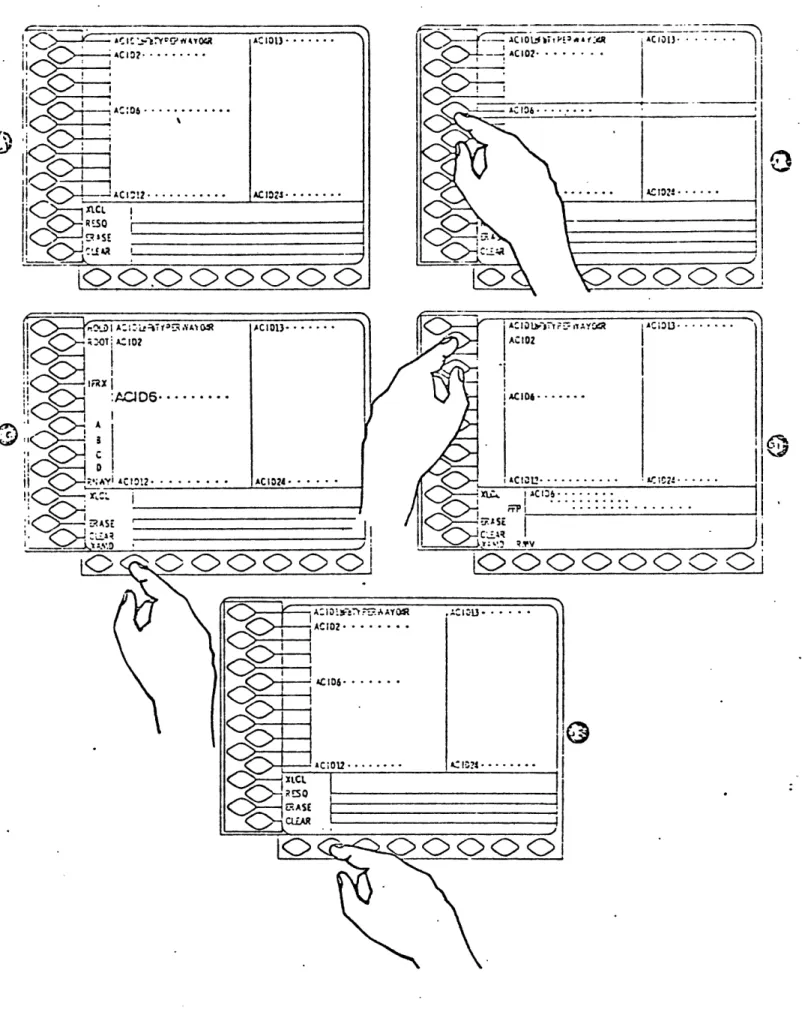
5 Example TIPS Display Presentation for Ground Control. 28 6 Example TIPS Display Presentation for Local Control.. 31
7 Example TIPS Display Presentation for Clearance Delivery... ... 34
8 The ATM/C Ground Control System... 49
9 Typical ETIS Message... ... ... .78
I. INTRODUCTION 1.0 Introduction
Air traffic control (ATC) is an evolutionary process. Elements of the system are designed for augmentation; new
features are introduced as they become feasible. Since safety is the prime concern of the ATC system, changes come about slowly. Once a modification becomes technically
possible, there are many years of lab and field testing before widespread implementation takes place.
As the system changes, so do the duties and require-ments of the controllers. A consequence of ATC evolution
is increased automation. The level of automation has grown over time; most of the systems now under development or planned for the future will offer further enhancements. In-herent in automation is increased controller interaction with computers. Computers have allowed routine controller tasks to be done automatically or to be simplified. In the future, controllers will be further aided by machines. A
large amount of information will be available on display or
by call-up. Computers will assist controllers by not only stating problems, but by offering solutions (and
The advanced ATC system concept considered in this
study will contain elements that are presently being
developed. Since none of these system components have been
implemented yet, their proposed functions and capabilities
are assumed. The purpose of this thesis is to investigate
controller and system interface/interaction in an advanced
ATC environment. It is a preliminary examiniation, intended
to focus attention on matters that will be of interest as
these systems are introduced. Suggestions are made as to
possible controller duties and tasks, and to modifications
of the system concepts. Emphasis is placed on tower
con-trollers and their display/data entry requirements. A
description of the present ATC system and controller
respon-sibilities is also presented.
There are areas of study beyond the scope of this
effort which will be addressed after more development and
testing is completed on the system components. The
feasi-bility of the interface suggestions will need to be
deter-mined. Human factor considerations are of prime
impor-tance, controller and pilot workloads must be resolved.
Controller acceptance of changes in tasks and duties will
II. BACKGROUND
Sections IU contains information regarding some sys-tems now under development. It is assumed in this thesis that they will be part of an advanced ATC system in the future. Descriptions are given in Section II to provide the background to discuss purposes, modifications and interface requirements in Section III.
Emphasis is placed on TIPS. Its display/data entry capabilities will change many of the present controller functions. TIPS may serve as an interface "hub" for some of the other system. There is also a definitive concept of TIPS available since a working model is presently being constructed.
2.0 The Present System
2.1 General Description
Control responsibilities are divided among 3
facili-ties:
1) Air Route Traffic Control Centers (ARTCC)
-control aircraft in the airspace between
terminal areas
2) Terminal Radar Control Facility (TRACON)
-handles all aircraft within the Terminal
Control Area (TCA) except for those controlled
by the tower. (The TCA extends to about 40
miles from the airport and to an altitude of
around 14,000 feet.)
3) Tower - responsible for arriving and departing aircraft on the airport surface or in its
vicinity (to about 5 miles)
The tower and TRACON are usually co-located at a major
airport. ARTCC's are distributed across the U.S.
The basic source of information to TRACON and ARTCC
controllers is the automated Radar Tracking System (ARTS).
ARTS III is the system used at over 60 major terminal areas
within the U.S. It provides automatic identification and
displays of identification, aircraft type, ground-speed and
altitude can be provided (in data blocks) for each aircraft
on the controller's radar screen. There is also the
capa-bility for semi-automated radar handoffs of aircraft
be-tween controllers, requiring a minimum number of actions.
The primary method of determining aircraft position
by tower controllers is through visual observation. (The
local controller is provided with ARTS information on a
BRIT-E display. He uses it mainly. to aid in specifying the
identification of arriving aircraft.)
All communication with aircraft is via voice radio
channel. Communication within a facility can be done
ver-bally by intercom or face-to-face. Exchanges between
facilities is done by intercom (tower-TRACON), phone or
teletype.
Flight plan data is provided to controllers on flight
strips. All IFR (instrument flight rule) flights have to
be filed in advance with the National Airspace System (NAS).
This information is then provided to the appropriate
fa-cility by the Flight Data Entry and Printout (FDEP)
sub-system. Tower and TRACON personnel handwrite flight strips
They also denote data changes or significant information by
marking the strip. Flight strips must be distributed to
the controllers. (In some instances, tower controllers use
the passing of flight strips to indicate handoffs.) Flight
strips can contain the following information:
Arrivals & Departures:
Arrivals:
Departures:
Aircraft identification (ACID)
Aircraft type
Computer I.D.
Beacon code
Previous fix
Coordination fix
Estimated Time of Arrival (ETA) at the coordination fix
Destination airport
Proposed departure time (PDT)
Requested Altitude
Departure Airport
Route
Controllers are provided with weather and status
in-formation (i.e., runways in use,. wind, visibility, etc.)
for aid in control duties and for relay to the pilots.
Some of this information is tape recorded by a tower
con-troller for inclusion in Automated Terminal Information
frequency whenever they want its information. ATIS is
updated approximately once an hour. See (section 4.2.1 for more on ATIS and the specific information contained it it.)
2.2 Tower Positions
A clearer picture of the present system can be gotten
from a functional description of each controller position.
A brief presentation of the tower positions is contained
below. A more detailed account of tower and TRACON
con-troller duties, tasks and available equipment is given in Appendix A.
2.2.1 Clearance Delivery (CD):
CD transmits clearances for departing aircraft and
ensures that all aircraft have current ATIS information. He coordinates with Departure Control on aircraft not represented in the NAS and also assists Flight Data when necessary.
2.2.2 Flight Data (FD):
FD is responsible for all FDEP and ARTS III activity required in the tower (i.e., flight strip preparation, ARTS
keyboard entries, etc.) He receives and verifies clearances from ARTCC or other ATC facilities. FD performs many of the tower 'housekeeping' duties (i.e., changing the roll in the teletype, compiling statistics, etc.). He has no direct communication to aircraft.
2.2.3 Ground Control (GC):
GC is responsible for routing all surface traffic
(aircraft and ground vehicles) on the airport except for that on active runways. He provides information and advisories to departing aircraft as needed.
2.2.4 Local Control (LC):
LC handles arriving and departing aircraft in the
vicinity of the airport and on active runways. He is responsible for maintaining separation standards and for checking weather and clearance. LC recommends to the
Team Supervisor the selection of active runways, and also works closely with the Cab Coordinator.
2.2.5 Cab Coordinator (CC):
CC works with LC, but with other tower controllers
TRACON. CC maintains close surveillance of inbound traffic
and determines runway usage. His major responsibility lies with arrivals, as compared to LC who must divide his
atten-tion among arrivals and departures. CC has no direct
communication with the aircraft.
2.2.6 Team Supervisor (TS):
TS directs the overall activity of the tower. He makes final decisions and provides assistance in operational
situations. CC monitors operating status of equipment and
communicates with outside agencies (i.e., the fire depart-ment, Coast Guard, etc.). CC is also responsible for the
3.0 The Next Step in Tower Automation: The Terminal Information Processing System (TIPS)
3.1 'TIPS General Description
3.1.1 Introduction
The current system used to communicate flight plan
information, the Flight Data Entry and Printout system
(FDEP), has inherent problems that constrain capacity and
worsen controller workloads. An all electronic system is
presently being designed to replace FDEP. It is the
Terminal Information Processing System (TIPS). TIPS will
accept, store, process, distribute and display flight and
other nonradar data for the terminal ATC facilities. Radar
controllers will be supplied this information on their
existing ARTS III Plan View Displays (PVD), while tower and
radar-support positions will be provided with new tabular
displays. Exchange of data via the displays will be
possi-ble between controllers, between facilities, and with other
information sources. (Each TIPS facility will be interfaced
with NAS.) The initial design of TIPS has been completed
and is now being developed by Lockheed Electronics Co./
Magnavox. Initial testing is scheduled for late 1980, with
TIPS will increase the availability of flight data to
tower and TRACON controllers. At present, only IFR flight
data is available from FDEP, and is often delayed due to
low data communication speed. TIPS will enable IFR and VFR
flight data to be displayed as soon as it is entered into
the computer base.
TIPS will facilitate intercontroller communication and
reduce controller workload. Today, flight strips must be
distributed to the controllers. With TIPS, information
will be transferred by a single computer entry action.
3.1.2 Display Description
A TIPS display/data entry unit will be provided to the
following positions in the tower: GC, LC, CD and FD. In
the TRACON, the arrival data and departure data positions
will also have TIPS units. Each unit contains:
- A CRT tabular display
- A 'Quick Action" data entry unit
- A 'Quick Action' hand control unit
Figure 1 gives an illustration of the display/data entry
unit. It will be 14 inches in height and depth and 18
inches in width. The display will be approximately 9 by
12 inches. (68 characters across). The general display
format is shown in Figure 2.
The lower third of the display will be the same for
all controller positions. A brief description of the areas
contained in it follows:
Readout Area - consists of 4 lines and will be used to display flight plans and requested weather and
status information. Paging capability is provided
for readouts of more than 4 lines.
Preview Area - Consists of 2 lines and will be used to review controller-entered data (via the
keyboard) prior to computer processing.
-Computer Response Area - consists of 2 lines and
will be used primarily to indicate the acceptance
(or non-acceptance) of manually entered data. It
will also be used to note significant flight data
(1)
TIPS DISPLAY
(2) TIPS QUICK ACTION
(3)
DATA ENTRY UNIT
TIPS KEYBOARD
(4)
TIPS
QUICK ACTION HAND
TIPS DISPLAY/DATA
ENTRY
UNIT
CONTROL
s-i 0 C- (0 -3 s-i
cr~
s-4 Cr) .4 '-Cl rr (~() niStatus Area - consists of 1 line and will be used to display general system information, such as active
runways and NOTAMS. The information will be
auto-matically updated as revised data enters the system.
Weather Area - consists of 1 line and will be used to display local weather information. It will be
updated automatically and by controller inputs.
Time - hours, minutes and seconds will be
dis-played in the right corner of the weather area.
The upper two thirds of the display will be used to
present departure and/or arrival flight lists. The specific
format for the tower positions is described in Section 3.2.
In Figure 2, the shaded areas on the left of the screen
de-pict where the available quick action functions will be
listed.
Procedures most often required of controllers are
incorporated into the quick action functions. The Quick
Action Data Entry unit provides an easy method for acting
on specific information being displayed. The unit consists
of 2 panels of pressure sensitive buttons located on the
operation of the Quick Action Data Entry unit is -presented
in Appendix B.l. Quick action functions available to each
tower controller are also discussed in Appendix B.2.2.
The Quick Action Hand Control Unit will be provided to
the local and ground controllers. It will permit them to
range up to 10 feet away from the TIPS display and still be
able to operate the quick action functions. Selected
in-formation or functions on the display will be identified
by moving a cursor which consists- of the intersection of a
vertical and horizontal line. Routine handoffs will be
accomplished by pushing a single button. An illustration
of the Hand Control Unit is shown in Figure 3.
The TIPS keyboard is adapted from the ARTS III
key-board. It will allow a full range of data entry and editing
actions. Necessary TIPS functions and capabilities will also
be provided. The keyboard is shown in Figure 4.
3.2 TIPS Description by Tower Position
3.2.1 Ground Control
GC will be presented with arrival and departure lists
containing flight data for the aircraft he is responsible
2 5
ctO , ICT IO4 SWITCH e-Ta o'SH3UiTON DEPARTURE ARRIVAL"PUSH5IUTi-TIPS QUICK ACTION HAND CONTROL
FIGURE 30
'
PEILIUM
ECERSPACE
LIII]
A]DDLIoDIJ
-LZII
FP ]D]D OM [~~~WWWWWEI
-Aircraft Identification (ACID): 2-7 characters
-Aircraft type: 2-5 characters
-Assigned Runway: 4 characters
Different list arrangements will be available. Included
will be alphanumeric ordering, chronological (by ETA)
ordering, and sorting into sublists by assigned runway.
The departure list format will be:
- ACID: 2-7 characters
- Flight status: "I" for IFR, "V" for VFR
- Aircraft type: 2-5 characters
- Assigned runway: 4 characters
- Coordination fix: 3 characters (or heading for VFR flights)
Possible list organization will be by alphanumeric or
chronological order, sorting by assigned runway, and by
order of handoff from Clearance Delivery.
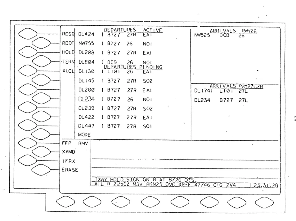
An illustrative display presentation for GC is shown
in Figure 5. The departures are sorted into Active (pilot
has contacted GC) and Pending (no contact yet) Lists.
Active is in chronological order and Pending is in
alpha-numeric order. GC can resequence a pending flight into
the Active list when contact is made. The display of "'NORE"
DL424 NW755 DL208 DLE04 CL 130
eATJIUBL_
SACT i VF I B727 27R EAl 1 8727 26 NO1 I 8727 27R EAl I DC9 26 NOI D.LEA RTU RES-PLNEI LIOI 2G EAl DL145 1 B727 27R S02 CL200 I 8727 27R EAl
CL234
1 8727
26
NO1
DL239 I B727 27R S02 DL422 I B727 27R EAl DL447 I B727 27R S01 IRR IV AL5 RWY2NW525
UC
26
ABRYALS
/L./R
DL1741
LIO
27L
DL234 8727 27L--
MORE
FFP RMV XAMD i FRX ERASE-IxW_ HOLD-; IJCN ON A AT8/60 .
AT_ _ 2_F-~47/46 C I 2
FIGURE 5 EXAMPLE TIPS DISPLAY PRESENTATION FOR GROUND CONTROL (GC-2) -RESC RDOT HOLC TERNv XLCL
are more pending entries and they have to be paged. The controller can display the rest of the information by press-ing the quick action button adjacent to "MORE". This is known as paging and will be required for any controller
dis-play where the number of entries exceeds the screen capacity. The arrivals are grouped by assigned runway and appear at the bottom of the appropriate list as they are handed off to GC. In this example, the ACID DL234 has been selected (it is enlarged) so the quick action functions that require ACID pre-selected are displayed. A description of the
quick action functions available to GC is contained later in Appendix B.2.2.2).
In Figure 5, the readout, preview, and computer re-sponse areas are blank. The status area provides the Lnfor-mation that the hold sign for Taxiway R at Runway 8/26 is
inoperative. The weather area states:
ATL R 2256Z: weather report issue for Atlanta at 2256 Zulu time.
M3V: barometric pressure 3
milli-bars and variable
BNK25: broken clouds at 25,000 feet
OVC 4R-F overcast; 4 mile visibility in rain and fog
47/46 temperature and dewpoint
C16 2V4 ceiling variable between 200 and 400 feet
The current Z-time is given in the lower right hand
corner.
3.2.2 Local Control
The arrival and departure lists presented to LC will
contain all the data included in the GC format, plus
additional information.
To the departure list will be added:
- Assigned beac.on code: 4 characters
- Requested altitude: 3 characters
LC Departure list organization will have available the
same arrangements as GC, except all departures will be
active.
The arrival list will also include:
- Assigned beacon code: 4 characters
- Approach type: 1 character
(e.g. "I" for ILS)
The same arrival list sorting options will be available to
LC as to GC.
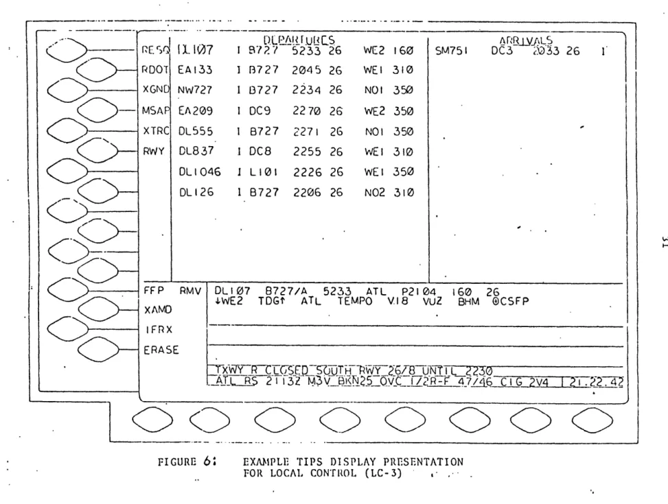
Figure 6 shows an example LC display. Departures are
listed in their take-off sequence order. Flight data for
each handoff from GC is added to the bottom of the
'--
r
1l.17
PDOT EA133 I XGND Nw727 I MSAP EA209 I XTRC DL555 I RWY DL837 I DLl046 I DL126 1 FFP XAMD RMV DLPAI .UUC.872?
5233 26
B727
2045 26
B727
2234 26
DC9 2270 26 8727 2271 26 DC8 2255 26 L101 2226 26 8727 2206 26WE2
WEt NO WE2 NO I WEt WEIN02
160 310 350 350350
310 350 310 I I SM751 DC3ARB..LVALS
2033 26 fDLI07 8727/A 5233 ATL P2104 160 26
IWE2 TDGt ATL TEMPO V18 VUZ BHM @CSFP
-T~VTY~R~C
E5
T
2230
ATE 21
i
I3
(25VC_~1/2R2__4.LI6T C G
?
7
jR2T47/V42
.
0 0
::)(
FIGURE
6
EXAMIPLE TIPS DISPLAY PRESENTATIONFOR LOCAL CONTiROL (LC-3) ..
-0
I FrXERASE
right are: ACID, flight status, aircraft type, beacon code, assigned runway, coordination fix, and requested altitude.
For arrivals, only one entry is shown. There never will be many flights listed since only a limited number are ever handled by LC at one time. The arrival list entry fields, from right to left are: ACID, aircraft type, beacon code, assigned runway, and approach type.
In this example, the quick action functions are dis-played because DL107 has been selected for further action. The flight plan will remain in the readout area until
action is taken to transfer the flight, clear the area, or select another flight.
The basic format for a Flight Plan Readout is:
line 1: ACID
1
Aircraft Data1
Beacon Code1
Speed1
Coordination Fix1
Coordination Time1
Altitude$
Assigned Runwayline- 2 and following: + Applicable Preferred Departure Route or Preferred Arrival/ Departure Route + V Route
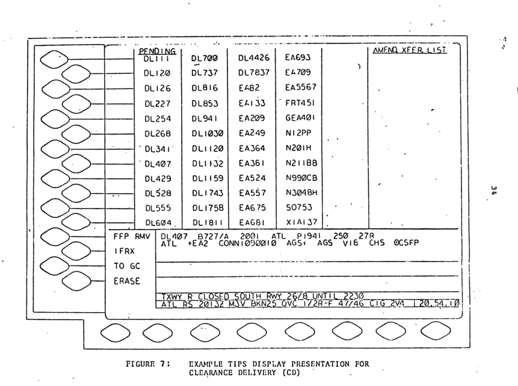
Clearance Delivery
TIPS will present CD with an ACID list containing all the aircraft scheduled to depart within a pre-determined
time period from the present. The ACID list will be or-ganized in alphanumeric or chronological (by PDT) order.
There will be an area on the display reserved for flights transferred from GC or LC for amendment. The entries will be of the form:
'ACID' from GC# (# specifies which GC or
-r or LC, if there are 'ACID' from LC# more than one)
Figure 7 shows the TIPS display for CD. The ACID list is organized in alphanumeric order (the method used by CD with flight strips today). Only 4 of the 5 possible col-umns for Pending Departures is being used. The Amendment Transfer List is blank.
The flight plan for DL407 is being displayed in the readout area. The quick action functions that involve
flight plans in the Readout Area are therefore displayed. Quick action functions which require pre-selection of an ACID are thus not shown, since they disappear after an ACID
II PFND I NG
DLI II
DL12.0
DL126
DL227
DL254
DL268
DL341
DL407
DL429
DL528
DL555
75Iii~
0-0
0-
0~-DL700
DL737
DL816
DL853
DL94
I
D
L
1030
DLI 120
DLI 132
DLI 159
DL 1743
DL
1758
DL 181 IDL4426
DL7837
EA82
EA 133
EA209
EA249
EA364
EA36 I
EA524
EA557
EA675
EAG8 IEA693
EA
709
EA5567
FRT451
GEA401
NI2PP
N201H
N21 I
BB
N990CB
N3048H$0753
XIA137 A&FFNQ xFFR LISTFFP
RMV DL407
B727/A
2001
ATL P1941
250 27R
ATL
+EA2
CONN1090010
AGSi
AGS
V16
CHS
OCSFP
I
FRX
TO
6C
ERASE
TXWY R CLOSED.50j)TwY
26/8UNTL230
AT
RS
2
3
KGS~vC l/2R-F47/4620T
CG 2V4
120.54.i0
00
<
0D 0c
0 0: KD
(c
FIGURE 7: EXAMPLE TIPS DISPLAY PRESENTATION FOR
CLEARANCE DELIVERY (CD)
is read out. A description of CD functions is given in
Appendix B.2.2.4.
Flight Data
FD will be given the same display format and ACID list as CD. The Amendment Transfer List will contain only en-tries sent to FD. All the quick action functions for the
FD position will be the same as for CD, except 'RDOT'. When implemented, it will always result in the full flight plan being displayed in the Readout Area (See Appendix B.2.2.5)
4.0 Other Systems Under Development
4.1 Discrete Address BeaconSystem (DABS)
An important capability of an automated ATC system will be discrete (directed to a particular aircraft) data
link of messages and information. Increased speed and integrity of transmitted messages, along with direct link to weather and advisory sources, will result in imporved safety of flight operations and a reduction in pilot and controller workload due to two-way voice communication.
The program presently underway at the FAA, with sup-port from MIT's Lincoln Laboratory is the Discrete Address Beacon System (DABS). The two-way digital data link capa-bility inherent in the signal structure of DABS will have applications in the following areas: ATC automation,
weather delivery, and terminal information. DABS is being
designed with maximum flexibility to allow for interface with a wide range of systems and avionics. This will per-mit the introduction of enhanced services in an evolutionary manner; DABS is applicable to services that will be
desir-able in an advanced automated ATC system. Initial imple-mentation of DABS is scheduled for the early 1980's. Some
of the functional uses of DABS now being considered are presented below. The interface of DABS in an advanced sys-tem, along with controller interaction is discussed in
4.1.1 Altitude Assignment Confirmation
Changes in altitude are tranmitted to the pilot by
voice communication. Since garbling or misunderstanding
can occur, pilots are required to confirm altitude
assign-ments over the voice channel. The potential errors
in-herent in this method can be eliminated by the use of DABS
data link to provide assignment and confirmation to pilot
and controller.
4.1.2 Takeoff Clearance Confirmation
Takeoff clearance is presnetly transmitted to the
pilot over a voice channel. Misunderstanding of messages
can occur by this method. A non-verbal controller
acti-vated "traffic light" type system has been developed by
the FAA. It is known as VCOVTC (for visual confirmation
of takeoff clearance). A supplement to this could be
clearance confirmation by DABS data link, which would also
allow acknowledgement of message receipt by the pilot.
4.1.3 Minimum Safe Altitude Warning (MSAW)
All ARTS III terminals presently have the capability
to provide a warning to the controller when an aircraft is
The controller must relay this message to the pilot. The time lag between detection and warning transmission could be reduced by using data link to automatically send a MSAW directly to the aircraft.
4.1.4 Automatic Traffic Advisor and Resolution Service (ATARS)
ATARS is a ground based system which will provide
collision avoidance information to aircraft equipped with a
DABS transponder, encoding altimeter, and a display. The ARARS computer will use surveillance data from DABS to for-mulate advisories. Messages will then be sent to the
air-craft. There will be different types of advisories depend-ing on the level of danger.
- When there is a potential threat of aircraft becoming proximate, the pilots will be alerted and informatoin will be sent to aid them in gaining-visual
- When the aircraft pose a potential
collision threat, additional
infor-mation will be displayed including
advisories to avoid maneuvers which
would aggravate the situation.
If the miss distance is projected to
be less than the es.tablished limit,
both aircraft will receive resolution
advisories at a predetermined time
before closest approach.
The responsible air traffLc controller will be sent an
alert message whenever a threat advisory is issued to an
4.2 Enhanced Terminal Information Service (ETIS)
4.2.1 Background: ATIS
A pilot needs certain local information such as local
weather, altimeter setting, RVR,etc. prior to landing at
or departing from an airport. At major airports, the
ter-minal information is provided by controllers and the
Auto-mated Terminal Information Service (ATIS). ATIS is a
recorded broadcast of relevent data and advisories
trans-mitted over a VHF communication channel, which the pilot
tunes in for reception. It is revised about once every
hour. On initial contact the pilot informs the controller
of the code of the latest ATIS broadcast he has heard. The
controller provides an update of necessary information and
relays advisories on instructions not contained in ATIS.
An ATIS broadcast contains the following data:
- airport identification
- sky condition below 10,000 feet
-- visibility if less than 7 miles
- obstructions to vision -- wind direction
- wind speed
- temperature and dewpoint
- altimeter setting
- instrument approach is use
- takeoff runway(s)
- NOTAM's and Airmen's Advisories
- "Check Density Altitude" message if temperature is 85 0F or more and tower altitude 2000 feet or more
- other pertinent information
- phonetic alphabet code of the message, and instructions for the pilot to acknowledge
receipt by informing the controller on initial contact
ATIS siginficantly reduces controller workload and the
loading of communication channels, but it has limitations.
Since a controller records the broadcast, there is the
poten-tial for human error. A pilot cannot choose or monitor a
particular item; he must listen to an entire broadcast. A
printed copy of the message is not available, so the pilot
must write it down or trust his memory. Also, due to the
line of sight characteristics of VHF transmission, ATIS is
available only locally and on limited areas of the airport
surface.
4.2.2 ETIS Features
By use of the DABS data link, most of the above
prob-lems can be circumvented, while adding new services and
features. The concept presently underdevelopment to
- Direct relay of most information using automated sensors, independent of a human operator.
- Ability to receive ETIS whenever DABS coverage is present
- Ability of the pilot to request only the informa-tion he needs
- Automatic transmission of alerts or significant changes in information
- Capability for making hand copy
- Elimination of most of the inherent ATIS errors
- Provision of digitized voice messages to non-DABS equipped aircraft.
4.2.3 Message Types
The following information will be included in ETIS:
- Runway(s) in use
- Approach(es) in use
- Sky condition
- Prevailing visibility
- Precipitation type
- RVR (Runway Visual Range)
- Center Field Wind
- Center Field/Runway Wind Vector Difference contained in wind shear alert (speed, direction)
- Temperature
- Dewpoint
- Altimeter Setting
- Rate of Barometric Pressure Rise (Alert (-- inches Hg
in -- minutes)
- Rate of temperature drop ( -- degrees F in - min.) (Alert)
- Thunder storm location, direction, speed (if available) (Alert)
- Density altitude (Alert)
- Airport advisories (such as ice patches, runway braking action reports, closed runways oc taxiways, noise
abatement procedures, construction equipment, out of service nav-aids, special instructions for VFR arrivals, etc.).
- Time of day of ETIS data (if required)
- (Wake vortex detection warnings?)
ETIS messages, with appropriate contents will be
dis-patched based on: phase of flight or aircraft location, a change on occurrence in ETIS data, and pilot request. The initial arrival ETIS message will be sent automatically to aircraft entering the terminal area. All the data from the
above list can be included in the message (alerts if appli-cable, RVR and density altitude if necessary). A Final
Approach message will be dispatched when the aircraft is near the outer marker or final approach fix (this is where
handoff to final control takes place). It will contain center field wind, runway wind and RVR or prevailing visibility. Departure ETIS will be transmitted upon pilot request prior to departure. It will contain the same information as an arrival ETIS message except for- the
exclusion of appraoch in use and RVR. Alerts will be sent automaticall , as soon as conditions warrant, to aircraft which have received the initial or departure ETIS message. The pilot will also be able to request any specific
items (s).
Non-DABS equipped aircraft will receive ETIS messages via a Digital Voice System (DVS) VHF broadcast. The time
of message formulation will be included to indicate validity of the data. Since the pilot must 'tune in' to receive the message, alerts and updates will not be able to be automa-tically dispatched. A controller will have to relay this
information.
ETIS will be compatible with other ATC system. Inter-face with TIPS is desirable since it will provide the con-trollers with constantly updated information, in addition
to a means to input non-sensor derived data into ETIS (e.g., runway in use). An interfaced ETIS/TIPS will also be able to furnish some of the information that an advanced
These interfaces and coordination are discussed later in
Section III (8.0).
4.3 Airport Surface Traffic Control (ASTC)
All aircraft and ground vehicles are directed on the
ramp and taxiways by the ground controller(s) and on the
runway(s) by the local controller(s). Communication is by
voice radio. During times of good visibility, the
control-lers base their decisions on visually surveyed information.
When viewing is diminished or obstructed, the controller
must rely on pilot position reports, in conjunction with
the display of surface radar data (if available).
Communi-cation and resulting controller workload increase greatly,
to the extent that GC, at times, becomes the pacing factor
in the execution of flight operations.
Airport Surface Detection Equipment (ASDE) is currently
in operation at twelve major airports. ASDE is a ground
surveillance radar system that provides a traffic display
to the ground controller. But a high level of
pilot-con-troller coordination is required since ASDE doesn't identify
its targets as does ARTS.
A new system known as ASDE-3 will have improved
Imple-mentation is planned for 30 airports over the next few years.
There are several aspects of surface traffic control where improvements can be made; a number of possible
solu-tions are presently being studied. Some form of ASTC will be needed in the advanced system: Scheduling shouldn't be restricted by ground delays. The particular system
implemented is not critical, so long as departing aircraft arrive at the threshold on schedu-le and arriving aircraft aren't delayed by ground control.
A system has been conceived that will use inductive
loops buried in the taxiways to detect aircraft. A
com-puter will determine routes. Stop commands will be issued via rows of red in-pavement lights. Directional
instruc-tions will be relayed by green centerline lights.
More desirable is to provide the identification and location of each aircraft. The Tower Automated Ground Surveillance System (TAGS), presently under study, will
utilize transponder responses to identify and provide labels to targets displayed by ASDE-3. Algorithms can be developed which will p-rovide conflict alerts and routing commands to
the controllers. With the introduction of DABS, instructions will be able to be sent to the pilot via his cockpit display.
The ASTC interface and resulting controller
require-ments for the advanced system is discussed in Section III
(6.0).
4.4 Air Traffic Management and Control Automation (ATM/C)
4.4.1 General Description
ATM/C will be an automatic, tactical decision making
system to reduce delays for both landing and take-off
operations at major airports (multiple runway operations
included). It will use radar tracking and other data to
generate flight plans and optimal runway schedules, and
pre-sent this information to the controllers on their existing
displays.
The ATM/C system can be modelled as a feedback control
system, all the elements of which are contained in:
The Aircraft Control (Navigation) System
Air-to-Air Link System
Ground Control System
Ground-to-Air Data Link System
Air-to-Ground Data Acquisition System
The basic state requirements consist of position, velocity and acceleration (P,P,P) of each aircraft target.
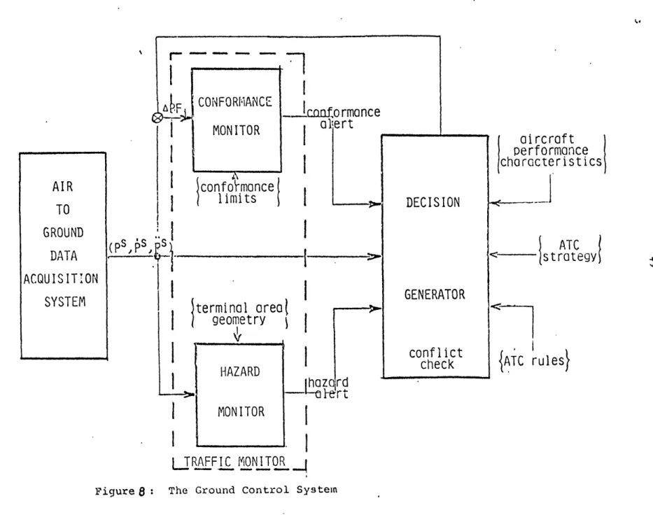
4.4.2 Ground Control System
The controllers will be primarily concerned with the Ground Control System: the Decision Generator and the
Traffic Monitor. Figure 8 is a block diagram of the Ground Control System, including inputs and outputs. The Decision Generator will be responsible for the flow of traffic. The input will be the state of each controlled aircraft
P, Ps, - time average values). The output will consist of a flight plan, F., for each aircraft. The flight plan,
concisely stated, is a set of time-points defining a curve in 4-dimensional space. The Traffic Monitor will ensure adherence to Ground Control decisions. It will also be responsible for enforcement of ATC safety rules and for generating a hazard alert when violation is imminent.
'Hazard' describes the relation between the surveillance positions of aircrat or of aircrft and unsafe or restricted airspace. 'Conflict'refers to the relation between flight plans. By definition, conflict will be checked by the
Decision Generator.
The ground control decision process can be further divided into two major functions: Runway Scheduling and
aircraft
performance
characteristics
ATC
1strategy
ATC rules
MONITOR
TRAFFIC jONITOR..
4and Traffic Flight Plan Generating.
Runway Scheduler: determines the best (according to some objective function) schedule of runway operations for all aircraft in the ATM/C System (landings and take-offs). The inputs are:
- The current ground control decision
- The nominal sequence of runway operations (the earliest preferred time for threshold arrival of each aircraft)
- The minimum required time separations at the runway threshold
- The maximum number of position shifts allowed
outputs:
- The runway schedule.
- The scheduler will be capable of responding to constraints/overides imposed by the supervising air traffic controller.
Traffic Flight Plan Genrator: Updates the aircraft flight plans subsequent to changes in the runway schedule. The inputs:
- The current routing decision, F
1 ,F2,...Fn
- The new runway schedule
- Minimum required airborne separations
- Current aircraft positions, P P PS...P
1 2 n
- The terminal area network geometry
- The aircraft performance characteristics
outputs:
* * *
- The new routing decision, F ,F2..,
4.4.3 Interfaces
Controller interaction will be with the command pro-cessor. The command processor will use flight plan data
to generate a set of commands which will navigate the aircraft along its assigned flight path. The controller will remain as the prime link between the ground system and the aircraft (though a scenario of direct data-linked
commands is envisionable). The set of allowable controller commands will be of the "radar vectoring" type (specified heading, velocity, altitude, etc.). The controller will be able to effect the decision process in thefollowing ways:
- Impose additional constraints to the scheduling process (e.g., immediate landing due to an aircraft emergency)
- Request for system reconfiguration (e.g., change the active runways, change the .ARC strategy, etc.)
- Validate commands for transmission to various aircraft
- Edit computer generated commands and initiate their their transmission process
ATM/C will aso have to interface with other systems.
It will need inforamtion regarding status and conditions (i.e., runways in use, RVR, winds, etc.). ATM/C will
inter-act with the surface traffic control system to get aircraft to their assigned runways (.on time). ATM/C interface in
III. AN ADVANCED ATC SYSTEM: REQUIREMENTS AND
SUGCESTED MODIFICATIONS.
An advanced ATC system, by definition, will
pro-vide new or enhanced capabilities to the controller.
Care must be taken for the augmented services and
in-formation to be made available in a readily accessible
and non-confusing manner. Loss of previous system
capa-bilities must be prevented.
The systems discussed in the previous chapters
will be the major components of the advanced system.
Contained in the next 4 chapters are some proposed
Mddi-fications and adaptations of these present system
con-cepts to allow for their interface with the controllers
and with each other in the advanced system. The-
objec-tive here is to suggest matters that should be
consider-ed as development proceconsider-eds on these systems.
The controller responsibilities will-remain basically
the same as in today's system - the prime concern bein8 safety. He will be provided with information from and
assisted in decision making by computerized systems
but final accountability remains with the controller.
Because of the importance of controller/computer
in-teraction, Section III is largely concerned with
dieglaY
54
entry unit functions and requirements are presented.
Since TIPS will be a "hub" for the other systems,
5.0 General
The following apply to TIPS and radar displays
in the tower and TRACON:
5.1 Controller Inputs
The controller will interact with the various
systems via his display/data entry unit. Certain
con-trollers will enter airport status or flight plan data.
Controllers will initiate control functions, call-up
needed information from the data base, and relay
mes-sages to the pilot. Required controller actions
should be as simple as possible.
5.2 Command Display
Computer generated decisions and commands will need
to be presented to the controller for validation before
any action is taken. The associated aircraft and the
time at which to initiate the instructions must be
in-cluded with the command message. Two possible methods:
- For displays with Flight Data Blocks (e.g.
ARTS PVD), include the message in the block
(will require an extra line or two).
(ACID and time, too) that the controller will
issue in the next period of time. This is
applicable to TIPS, where there won't be enough
space in the aircraft's flight data fields.
The ATM/C system will issue vectoring commands and the
ASTC system will provide ground routing instructions.
Some example message formats are given in Appendix C.
Message will be data-linked to DABS equipped
air-craft and provided by voice radio to others. An
indi-cation that the message is received and acknowledged
uy the pilot will be provided (see Section 5.3).
Con-trollers will have quick action means to automatically
relay directions to DABS aircraft (see Section 5.7).
5.3. Pilot Response
A means to indicate data linked cockpit responses
to ground initiated requests will be required. There
are several possible methods:
1.) Have a dedicated area located on the
display to present the pilot responses.
(For TIPS, this could be a portion of the
Conputer Response Area.) The replies may
displayed message WILCO UNABLE QUEST? NO/REP meanin~c.
Acknowledged, will comply
Unable to execute command
question regarding previous
request, provide more
in-formation,
no reply (displayed after
a predeteriaind time period)
note: it may be desirable to include the ACID
of the responding aircraft (eg. AA123: WILCO)
2.) Since the message to be data linked to the
pilot will be presented on the controller's
display, have the response appear next to the
message. A single letter or symbol may be all
that will be necessary (i.e. W,U,?,NR).
3.) In some instances it may be desirable to have
redundancy or a longer lasting reminder of the
request and response. An example is to denote
clearance confirmation in the aircraft's flight
data field on the TIPS display (see 6.1.3 and
5.4 Alerts
ARTS, ATM/C, ASTC and ETIS will automatically
re-lay alerts and notifications of critical situations to
the appropriate controller (s), and in many cases, to
the pilot as well. Provision must be made to
distin-guish the type and urgency of each alert. An alert
will remain in effect until it is acknowledged and the
situation is rectified. Some methods for presenting
alert messages follow:
1.) Have a dedicated alert area where the type of
alert will appear, and if necessary, the
aircraft to which it applies. (For TIPS, a
section of the Preview Area could be used).
2.) For aircraft related alerts, have the message
appear in the Flight Data Block or field,
overwriting the information already there.
3.) Couple the above methods with another
indi-cator. Examples are: audible alerts,
warn-ing lights, flashwarn-ing the displayed alert.
Audible alerts will especially be needed in
the tower, where ground and local controllers
5.5
Flagging
Certain aircraft status or state information can
be denoted by marks or symbols instead of printed words.
For example, in today's system the controller puts a
check mark on the flight strip when the assigned
alti-tude is transmitted.
The displays in an advanced
sy-stem should provide automatic and/or controller
ini.-tiated means of underlining, blocking in, or adding
sym-bols to pertinent data.
5.6
Avionics Capability
The computer systems and controllers alike will
have to be informed of the communication and
naviga-tion capabilities of each aircraft. All aircraft
fly-ing within a TCA are required to have a transponder,
but there will be a mix of ATCRBS and DABS.
Though
the DABS system will accept data communication from
ATCRBS transponders, data-linked messages will not be
possible since ATCRBS doesn't have display
capabili-ties.
There will also be various DABS cockpit display
capabilities among the aircraft mix.
These differences affect how information will be
communicated. A Digitized Voice System (DVS) may be
included in the DABS system.
This will provide messages
to non-DABS equipped aircraft over a radio frequency.
All forms of communication will be supplemented by
con-troller voice transmission via radio, when required.
The DABS ground system will be able to
automati-cally determine avionics capability from the
transpon-der response. The controller must have this
informa-tion displayed to him. Each controller display in the
advanced system will be able to present beacon codes.
The beacon code can be used to denote avionics by:
- including a single-character symbol with each
code to indicate type of avionics.
- allocating beacon code numbers according to the
avionics capability.
Control message format will depend on navigation
capability (e.g. issue a series of way points for RNAV
equipped aircraft). This information will be determined
and provided to the computer systems-and controllers as
described above.
Any avionics malfunction or failure must be
report-ed to the controllers and computer so that appropriate
action can be taken. Controllers will be alerted as
5.7 Command Validation and Relav
ATM/C and ASTC will present computer generated
control decisions to the controller for validation and
relay to the appropriate aircraft. The controller
should be provided with a simple input method to
acknow-ledge a displayed command or to indicate that he will
override the computer decision. In all cases, there
will be a time period between when the command is
dis-played and when it must be issued. For some commands,
the controller may pre-validate them (the instructions
will then be automatically dispatched to the aircraft
by the computer at the appropriate time). Input functions
to be available on initial display of a command
instruc-tion:
- 'ACKNOWLEDGE'- Validates the computer decision;
indicates to the computer that
the action will be taken
-'PREVAL' - Validates the command and also
tells the computer to
autonati-cally dispatch the message at the
appropriate time.
-'OVERRIDE' - Informs the computer that the
command than the one displayed.
-'OVERRIDE' can be used after'ACKNOWLEDGE' or 'PREVAL' if the controller should change his mind.
For dispatching messages, the cor.troller should
be provided with a
quick
action input 'AELAY'.
'RELAY' will transmit a designated (displayed in a
special area, or flagged) command to tha appropriate
aircraft.
For non-DABS equipped aircraft the controller
will use the voice channel, so 'RELAY" will be used to
inform the computer that the command has been issued.
Both systems will provide alerts to the controller
and the pilot when the aircraft deviates from its
pre-sented path or when there is danger of a collision.
In the case of a collision alert, where expendiency
is required, rectifying commands will be linked
direct-ly to the cockpit without controller validation.
This
will avoid the time lag inherent in controller relay.
Hopefully collision alerts will be rare, since the paths
of all aircraft will be predetermined and flight
pro-gress will be monitored by ATM/C.
5.8 Reconfiguration of Active Runways
ASTC will have to interact with ATM/C so that
departing aircraft are delivered to the correct
run-way at the appropriate time. Provision must also be
made to route arriving aircraft from the landing runway
to its assigned gate (section 6.2.2) To accomplish the
above, and for ATM/C to make the appropriate Air
rout-ing comp'utations, the status of active runway and
taxi-ways must be included in the computer data base. Active
runway changes, along with individual aircraft runway
assignments, will be automatically dispatched to ATM/C,
ASTC, ETIS and TIPS systems so that necessary
coordi-nation action will take place.
For the actual process of reconfiguring active
run-ways, the Team Supervisor (TS) in the tower will be
re-sponsible for the final decision. He will be aided by
computer derived suggestions based on the following
in-formation:
- predetermined noise abatement procedures
- weather (e.g. thunder storm avoidance)
- general wind conditions
- optimal cross wind for wake-vortex avoidance
- -changes in RVR, wind shear, etc.
- runway or taxiway status (i.e. ice, constructio,, etc.)
The computer system will automatically notify the
TS (or another controller) when reconfiguration is
neces-sary, or the TS may initiate a change and enter it into
the data base, The time for which the reconf'.guration
will be in effect must be made known. The TS will
in-teract with the system via a TIPS display/data entry
unit (the tower Input/Output Terminal).
5.9 TIPS List Display Requirements
The arrival and departure lists on the GC and LC
display should be chronologically ordered automatically
according to runway. For each tircraft the appropriate
coordination time should be displayed:
- for LC Arrival: display ETA (estimated time of arrival)
- for CC Arrival: display ETC (estimated time to gate)
- for GC Departure (Pending):display ETT (esti-time to taxiin-)
- for GC Departure (Active): d-isplay PDT (proposed departure time)
- for LC Departure: display PDT
5.10 ATM/C Information Requirements
The ATM/C system will require access to and input