Smart co-phasing system for segmented mirror telescopes
Juan F Simar*
a, Yvan Stockman
a, Jean Surdej
ba
Centre Spatial de Liège, LIEGE Science Park, Avenue du Pré-Aily, 4031 Angleur, Belgium;
b
Institut d'Astrophysique et de Géophysique, Université de Liège, Allée du 6 Août 19c, 4000 Liège,
Belgium
ABSTRACT
Space observations of fainter and more distant astronomical objects constantly require telescope primary mirrors with a larger size. The diameter of monolithic primary mirrors is limited to 10 m because of manufacturing and logistics limitations. For space telescopes, monolithic primary mirrors are limited to less than 5 m due to fairing capacity. Segmented primary mirrors thus constitute an alternative solution to deal with the steadily increase of the primary mirror size. The optical path difference between the individual segments must be close to zero (few nm) in order to be diffraction limited over the full telescope aperture. In this paper a new system that may co-phase 7 segments at once with the light of a star and without artificial one is proposed. First the measuring methods and feedback system is explained, then the breadboard setup is presented and the results are analyzed and discussed, finally a comparison with Keck telescope is performed. This system can be adapted in order to be used in the co-phasing system of future segmented mirrors, its dynamic range starts from several hundred of microns till some tenths of nanometers
Keywords: Active optics, phasing, PSF, OTF, FFT
1. INTRODUCTION
In space observation, one of the challenges is to observe smaller and fainter objects. This can be achieved by increasing the telescope diameters. So, increasing the primary mirror diameters of the telescopes is the challenge solution but it is technically impossible to manufacture mirrors bigger than 10m in diameter. One solution is to manufacture several smaller mirrors (called segments) and co-phase them so they can behave like a single big mirror. Several co-phasing methods have been developed during the past years to break the 10m barrier.
Also, for space telescopes, the maximum diameter of a single mirror is 5m due to fairing capacity, so folded segmented primary mirrors shall be developed.
This paper describes the results of a light co-phasing setup mounted in laboratory. This setup is able to correct a piston from 200µm to 15 nm based on coarse (200µm to 300nm) and fine (300nm to 15nm) measurement methods.
Both measurements are then chained in a feedback system in order to completely co-phase and keep aligned the segments.
1.1 Coarse measurement
In the coarse measurement, a mask is placed in front of the telescope, preferably perpendicular to the collimated rays. This mask samples the incoming light of a star in 7 sub-pupils (round holes) each one in front of each segment. Then the light of all the holes pass through a spectral filter, and finally a CCD sensor records the Point Spread Function (PSF). The coarse measurement analyses the MTF (Modulation Transfer Function) of the OTF (Optical Transfer Function) and it is calculated from the PSF. This method is largely described in [1].It was implemented and tested with a breadboard presented hereafter.
1.2 Fine measurement
The fine measurement uses the same OTF as the coarse measurement, but the analysis is achieved over the PTF (Phase Transfer Function) instead of the MTF. This method is explained in [2] and was implemented and validated with the breadboard presented hereafter.
2. CO-PHASING FEEDBACK SYSTEM IMPLEMENTATION
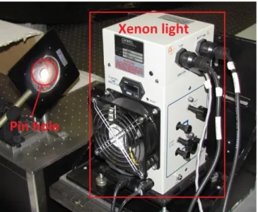
2.1 Optical setupFirst, the light generated by a Xenon bulb illuminates a pinhole (see Figure 1) to simulate a star.
Figure 1. Xenon light and pinhole
The light from the pinhole goes to an off-axis parabola to simulate a telescope primary mirror and a mask to simulate the segments (S1 to S7). They are illustrated in Figure 2. In this case, each sub-pupil covers the entire surface of each segment but in a real telescope, each sub-pupil covers only a small part of each segment.
Figure 2. Off-axis parabola and mask for 7 segments used in the coarse and fine measurements.
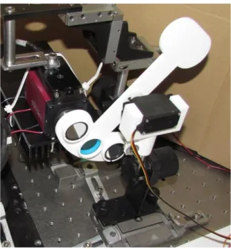
The light of the segments S2 to S7 goes to the left flat mirror (see the Figure 3) and the light of S1 goes to the right flat mirror. The S1 mirror can be moved by a piezo-electric actuator in order to adjust the Optical Path Difference (OPD or piston error) between the light from S1 and the other segments. The corner cube is used with an Agilent HP5519A interferometer to compare and verify the measurements. The piezo-electric actuator is hidden behind the S1 mirror so it cannot be seen on the picture.
Figure 3. Flat mirrors and corner cube
The light from the flat mirrors converges to the CCD camera passing through three different filters (see Figure 4), one at a time. In this way, the CCD records the PSF of the segments S1 to S7.
Figure 4. Filter wheel and camera
The piezo-electric actuator and the filter wheel (Figure 4) are controlled by a PC using the control card shown in Figure 5.
Figure 5. Control card
2.2 Coarse measurement implementation
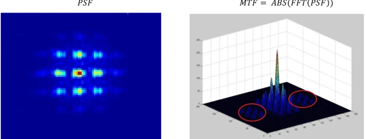
The coarse measurement was implemented by calculating the absolute value of the amplitude of the Fast Fourier Transform of the PSF (See the MTF in Figure 6) and measuring the height of the red circled peaks.
𝑃𝑆𝐹 𝑀𝑇𝐹 = 𝐴𝐵𝑆(𝐹𝐹𝑇(𝑃𝑆𝐹))
Figure 6. PSF (left) and MTF (right) used in the coarse measurement
2.3 Fine measurement implementation
The fine measurement was implemented by calculating the argument of the Fast Fourier Transform of the PSF (see the PTF in Figure 7) and measuring the average height of the yellow dotted peaks.
𝑃𝑆𝐹 𝑃𝑇𝐹 = 𝐴𝑅𝐺(𝐹𝐹𝑇(𝑃𝑆𝐹))
Figure 7. PSF (left) and PTF (right) used in the fine measurement
2.4 Feedback system implementation
The feedback system was implemented in the following way: The PC records the PSF with the CCD camera and then calculates the MTF and PTF from the PSF. After that, it measures the peaks of the MTF and PTF (coarse and fine measurements, respectively) and sends the information of the coarse measurement to the piezo-electric actuator in order to correct the piston error. When the coarse measurement of the first filter reaches 0, the PC changes to the second filter and it measures again. When the coarse measurement of the second filter reaches 0, the PC changes to the third filter and it measures again. When the coarse measurement of the third filter reaches 100nm, the PC changes back to the first filter and measures again but this time it measures the peaks of the PTF. Finally It performs measures and corrects the piston from the fine measurement indefinitely in order to maintain the piston error to less than 15nm.
3. RESULTS
Table 1 illustrates the measurements achieved with the system when the whole co-phasing is finished.
Table 1. Results of piston measurements after the co-phasing is finished. Average of 50 measurements (Left column), standard deviation (Center column), HP55191A measurement (Right column, this measurement have a known Standard Deviation of 10nm).
Average (nm)
2xStdDev (nm)
HP5519A (nm)
1 8 -2 0 14 -12 1 16 1 1 10 1 0 12 -2 1 12 -2 0 14 -2 -1 14 -1 0 16 -21
The measurements performed with the system here above presented show good correlation with a interferometer (HP5519A) uses as standard. The average of the measurements does not exceed +/- 1nm so it is more precise than the co-phasing requirements (typical wavelength of 550nm/40=13.75nm).
4. COMPARISON WITH KECK
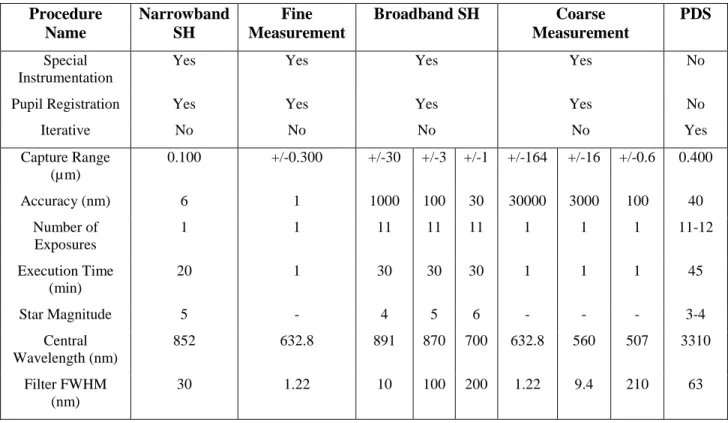
The following table has been adapted from [8] in order to compare the Keck measurement system to the system described in this paper.
Table 2. Comparison with Keck telescope system
Procedure
Name
Narrowband
SH
Fine
Measurement
Broadband SH
Coarse
Measurement
PDS
Special InstrumentationYes Yes Yes Yes No
Pupil Registration Yes Yes Yes Yes No
Iterative No No No No Yes Capture Range (µm) 0.100 +/-0.300 +/-30 +/-3 +/-1 +/-164 +/-16 +/-0.6 0.400 Accuracy (nm) 6 1 1000 100 30 30000 3000 100 40 Number of Exposures 1 1 11 11 11 1 1 1 11-12 Execution Time (min) 20 1 30 30 30 1 1 1 45 Star Magnitude 5 - 4 5 6 - - - 3-4 Central Wavelength (nm) 852 632.8 891 870 700 632.8 560 507 3310 Filter FWHM (nm) 30 1.22 10 100 200 1.22 9.4 210 63
The Fine Measurement is comparable with the Narrowband SH system and the Coarse Measurement is comparable with Broadband SH system.
Additional assessment shall be realized in order to estimate the required Star Magnitude.
The execution time is significantly less but the exposure time used in the system is 0.3s in comparison with 30s for the Keck system.
5. CONCLUSIONS
A very compact and light system has been presented. The uncertainty of this system is well below the co phasing requirements. These qualities allow his use on space as well as on ground-based telescopes. However in order to be implemented on ground-based telescopes, an additional system capable to correct for the atmospheric turbulence is necessary.
The system speed and precision can be improved using high speed camera and optimized piezo-electric controller card.
The described system has several advantages in comparison with the Keck telescope system but additional assessment shall be realized to validate it in a real segmented telescope.
REFERENCE LINKING
journal paper: [1] Simar, J.F., Single wavelength coarse phasing in segmented telescopes, Applied Optics, Vol. 54, Issue 5, pp. 1118-1123 (2015).
proceedings paper: [2] Géraldine Guerri, Steeve Roose, Yvan Stockman, Alexandra Mazzoli, Jean Surdej, Jean-Marc Defise. First steps of the development of a piston sensor for large aperture space telescopes. SPIE, vol. 7731, p 165 (2010).
REFERENCES
[1] Simar, J.F., Single wavelength coarse phasing in segmented telescopes, Applied Optics, Vol. 54, Issue 5, pp. 1118-1123 (2015).
[2] Géraldine Guerri, Steeve Roose, Yvan Stockman, Alexandra Mazzoli, Jean Surdej, Jean-Marc Defise. First steps of the development of a piston sensor for large aperture space telescopes. SPIE, vol. 7731, p 165 (2010). [3] Wikipedia, https://en.wikipedia.org/wiki/Standard_deviation
[4] Fabien Baron, Isabelle Mocoeur, Frédéric Cassaing, Laurent M. Mugnier. Unambiguous phase retrieval as a cophasing sensor for phased array telescopes. J. Opt. Soc. Am. A., 1000, Vol. 25, No. 5, May 2008.
[5] François Hénault. Multi-spectral piston sensor for co-phasing giant segmented mirrors and multi-aperture interferometric arrays. J. Opt. A: Pure Appl. Opt., 11 125503, 2009.
[6] G. Chanan, M. Troy, F. Dekens, S. Michaels, J. Nelson, T. Mast, and D. Kirkman. Phasing the Mirror Segments of the Keck Telescopes: The Broadband Phasing Algorithm. Appl. Opt., 37(1):140-155, 1998.
[7] Sebastien Van Loo, Etude de Senseurs de Front d'Onde Apliqués à la Synthèse d'Ouverture Optique pour la mesure du Piston et du Tilt, Université de Liège, (05/2003).
[8] Gary A. Chanan, Mitchell Troy, Catherine M. Ohara, Phasing the primary mirror segments of the Keck telescopes: a comparison of different techniques, Proc. SPIE 4003, Optical Design, Materials, Fabrication, and Maintenance, 188 (July 20, 2000)