Alternative Energy Design Toolkit
by
Sittha Sukkasi
Sc.B. Brown University (2002)Submitted to the Department of Mechanical-Engineering in partial fulfillment of the requirements for the degree of
Master of Science in Mechanical Engineering
at the
MASSACHUSETTS INSTITUTE OF TECHNOLOGY
September 2004
MASSACHUSETTS INSTITUT. OF TECHN=LCX%'
JUN 16 2005
LIBRARIES
©
2004 Massachusetts Institute of Technology. All rights reserved.The author hereby grants to Massachusetts Institute of Technology permission to reproduce and
to distribute copies of this thesis document in whole or in part.
Signature of A uthor... ... ... Department of Mechanical Engineering
23 August,2004
Certified by ... ..
David Wallace Esther and Harold E. Edgerton Associate Professor w f Thesis Supervisor
Alternative Energy Design Toolkit by
Sittha Sukkasi
Submitted to the Department of Mechanical Engineering on 23 August 2004, in partial fulfillment of the
requirements for the degree of Master of Science in Mechanical Engineering
Abstract
This thesis concerns the concepts, structure, and applications of the Alternative Energy Design Toolkit. The toolkit is aimed to provide a widely accessible, easy to use, flexible, yet power-ful modeling environment for assisting design associated with renewable energy technologies. Exchanges of ideas and knowledge among the users are also highly encouraged and facilitated.
The toolkit is composed of three important components: a collection of models that are fun-damentals of renewable energy design, a modeling environment called DOME, which is used as
the toolkit's enabler, and a supporting Web site.
At the beginning, a comprehensive survey of existing tools for renewable energy design is presented. Then, the detailed descriptions and key capabilities of the toolkit's components are provided. In addition, a collection of solar energy models, which is the initial set of models in the toolkit, is also presented.
The toolkit is utilized in two design scenarios: a design of a stand-alone PV system, arid a trade-off analysis of a hybrid PV-diesel electricity system. In both design scenarios, the models in the toolkit are proven to be useful and convenient resources. The processes of making the representations of the systems are straight-forward, and the analysis mechanisms that the toolkit provides make the design process simple yet effective.
Thesis Supervisor: David Wallace
Acknowledgements
I would like to express my gratitude to all those who helped make this thesis possible. In particular, I would like to thank my thesis advisor, Professor David Wallace, for his insightful guidance and support. I sincerely appreciate the opportunities he had provided me to conduct this research of my true passion.
I also would like to acknowledge the people in MIT CADlab, who had always kindly helped each other through many difficult tasks and stressful deadlines; Qing Cao, Twiggy Chan, Charles Dumont, Renu Fondeker, Wei Mao, Keith Thoresz, Professor David Wallace, Jakub Wronski, and especially Elaine Yang.
Specially, I am grateful to my father, my mother, my grandparents, and my brother for their warm support and belief in me from a distance. I also thank my dear friends and room-mates, Sup Akamphon and Vee Boonyongmaneerat. Finally, I thank Parima "Looktarn" Dam-rithamanij for her love and encouragement.
Contents
Contents 3 List of Figures 7 1 Introduction 10 1.1 M otivation . . . . 10 1.2 O verview . . . . 11 2 Background 13 2.1 Related W ork . . . 132.1.1 Tools that support all types of renewable energy technologies . . . 13
2.1.2 Tools that support a few types of renewable energy technologies . . . 15
2.1.3 Tools that support only one specific renewable energy technology . . . . . 17
2.1.4 Tools that support designs with renewable energy technologies for buildings 21 2.2 Identification of challenges . . . . 24
2.2.1 Observations from the surveyed tools . . . . 24
2.2.2 Lessons learned . . . 26
2.3 D O M E . . . 28
3 Alternative Energy Design Toolkit 30 3.1 O verview . . . 30
3.2 M odel Collection . . . 31
3.2.1 Usability of the models . . . 31
3.2.3 Multiple forms of user interfaces . . . .3
3.2.4 Minimal third-party software dependencies . . . 34
3.2.5 Coverage of key elements . . . 34
3.2.6 Reliability and validation of models . . . 35
3.2.7 Extensibility and knowledge sharing . . . 36
3.3 DOME.. . .. . . .. . .. ... . .. ... . .. . .. . . . .. .... .. . .. .. 36
3.3.1 Accessibility through the Internet . . . 37
3.3.2 Multiple interfaces for end-users . . . 38
3.3.3 Computation-status feedback for end-users . . . 42
3.3.4 Implementation of new models . . . 43
3.3.5 Wrapping of third-party models . . . 44
3.3.6 Deployment and permission settings . . . 45
3.3.7 Model integration . . . 47
3.3.8 Computation with distributed resources . . . 49
3.3.9 Declarative model integration and parameter mappings . . . 50
3.3.10 Solving mechanism . . . 51
3.3.11 Collaborative design . . . . 56
3.3.12 Informed decision making with an optimization tool . . . . 56
3.4 Supporting Web site . . . .
58
3.4.1 Bridge between the WWW and the WWSW . . . . 58
3.4.2 Web site hosting of DOME applet . . . . 58
3.4.3 Model and idea transactions . . . 60
3.4.4 Information base . . . 60
4 Solar energy models
4.1 PV system and components models . . . . 4.1.1 PV module operational characteristics 4.1.2 PV system load breakdown . . . . 4.1.3 PV array operation . . . . 4.1.4 PV system controller operation . . . . 4.1.5 Lead-acid battery operation . . . .
62 62 62 64 65 66 68 . . . . 3 2
4.1.6 Inverter operation
4.2 Flat-panel collector models . . . 70
4.2.1 Top heat loss of a flat-panel collector . . . . 70
4.2.2 Efficiency of a flat-panel collector . . . . 71
4.3 Economic analysis models . . . . 73
4.3.1 PV system life-cycle costing . . . . 73
4.3.2 Engine-generator system life-cycle costing . . . 74
4.4 Energy analysis models . . . 76
4.4.1 PV module life-cycle energy analysis . . . 76
4.4.2 Simplified PV module arid battery energy analysis . . . 79
4.4.3 Simplified diesel generator energy analysis . . . 81
4.5 Solar radiation models . . . 81
4.5.1 Sun-earth geometric relationship . . . 81
4.5.2 Extraterrestrial radiation . . . 86
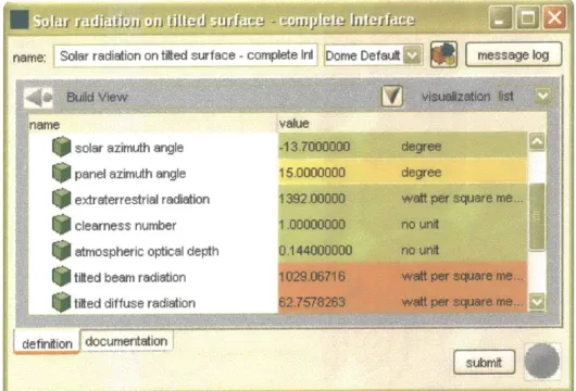
4.5.3 Solar radiation on a tilted surface . . . 86
4.5.4 Global irradiance on inclined surface . . . 88
4.6 Miscellaneous models . . . 89
4.6.1 CO2 emissions from electricity generating systems . . . 89
4.6.2 Solar irradiance profile . . . 90
4.6.3 Load profile . . . 92
5 Sample design scenarios 93 5.1 Scenario I: Design of a stand-alone PV system . . . . 93
5.1.1 Components models . . . . 93
5.1.2 Integration of models . . . . 96
5.1.3 Customized user interface . . . . 99
5.1.4 Results and discussion . . . 101
5.1.5 Summary . . . 107
5.2 Design scenario II: Trade-off analysis of a hybrid PV-diesel system . . . 107
5.2.1 Components models . . . 108
5.2.2 Integration of models . . . 109
5.2.3 Customized user interface . . . .111
5.2.4 Design-scan analysis . . . .112
5.2.5 Results and discussion . . . .112
5.2.6 Sum m ary . . . .116
6 Conclusions 117 6.1 Sum m ary . . . 117
6.2 Future work . . . 120
Bibliography 122 Appendix A. Summary of related work survey 128 Appendix B. Data used in the sample scenarios 133 Design of a stand-alone PV system . . . 133
Trade-off analysis of a hybrid PV-diesel system . . . 136
Appendix C. Snapshots of customized GUIs 141 Trade-off analysis of a hybrid PV-diesel system . . . 141
List of Figures
3-1 DOME run browser. ... ...
3-2 Standard user interface of a model. . . . . 3-3 Graph visualization in a standard interface. . . . . 3-4 Design system matrix visualization of a standard interface. . . . . 3-5 Custom ized interface. . . . . 3-6 Color coding showing status of parameters' values during a computation... 3-7 Built-in mathematical programming mechanism in DOME. . . . . 3-8 M atlab script. . . . . 3-9 Wrapped MATLAB model with references to the variables in the original script. 3-10 Setting of editing permissions during deployment. . . . . 3-11 Setting of use permissions during deployment. . . . . 3-12 Integration consisting of six resource models and one integration model. . . . . .
Mapping between parameters from two resource models. . . . . . Graph visualization of a large, integrated project. . . . . Causality information of parameters in a mathematical relation. . Causality information for model X. . . . . Causality information for model Y. . . . . Causality information for model Z. . . . . Dependency information of model X. . . . . Dependency information of model Y. . . . . Dependency information of model Z. . . . . Dependency information shared by model X. . . . .
. . . 48 . . . 49 . . . . 5 1 . . . 52 . . . 52 . . . 53 . . . 53 . . . 53 . . . 53 . . . 54 37 38 39 40 41 42 43 44 45 46 46 47 3-13 3-14 3-15 3-16 3-17 3-18 3-19 3-20 3-21 3-22
Dependency information shared by model Y. . . . . Dependency information shared by model Z. . . . . Complete dependency information collected by DOME, based on the information 3-23 3-24 3-25 3-26 3-27 3-28 3-29 3-30 4-1 4-2 4-3 4-4 4-5 54 54 . . . 55 . . . 55 . . . 55 . . . 55 . . . 57 . . . 59 . . . 63 . . . 63 . . . 67 . . . . 70 . . . . 71
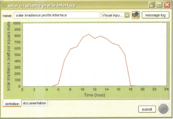
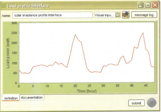
4-6 Illustrations of a site's location P, its latitude L, solar declination 6, solar alti-tude a, and solar-hour angle h, [17]. . . . . 4-7 Positions and angles of the earth to the sun, for the winter solstice (Dec 21) [17]. 4-8 Solar declination through out the year [17]. . . . . 4-9 Sun paths for the summer and winter solstice, and the autumn and spring equinoxes, shown with numbers signifying the hours of the day [17]. . . . . 4-10 Angles used in calculations of solar radiation on a tilted surface [17]. . . . . 4-11 Custom interface with an interactive chart for forming a profile of solar irradiance. 4-12 Updated profile after a user's click on the chart .. . . . . 4-13 Custom interface with an interactive chart for forming a profile of electricity load 82 83 83 84 87 90 91 demand... 92 5-1 5-2 5-3 5-4
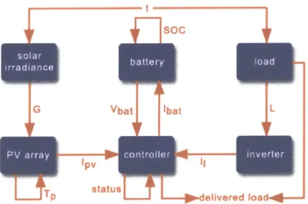
Solar irradiance profile used in design scenario I. . . . . Load profile used in design scenario I. . . . . Declarative connections between the models in design scenario I. . . . . Information flows between the models in design scenario I. . . . .
94 95 96 97 shared by all models. . . . .
Dependency information for model X to autonomously solve itself. Dependency information for model Y to autonomously solve itself. Dependency information for model Z to autonomously solve itself. Trade-off curve plotting various optimal options (red dots)... DOME applet embedded in an HTML page. . . . .
Equivalent circuit of a solar cell [29]. . . . . I-V characteristic curve of a solar cell [29]. . . . . Energy/current flow in a PV power system. . . . . Schematic diagram of a solar collector [17]. . . . . An absorbing plate as a fin connecting two adjacent channels. . . .
5-5 The integration after being added with a time iteration in design scenario
I.
. . . 985-6 Customized user interface of the integration in design scenario I. . . . . 99
5-7 Plot of the battery current while being updated after every iteration step, in design scenario I. . . . 100
5-8 Prediction of delivered load demand in simulation #1 of design scenario I. . . 101
5-9 Prediction of battery's voltage in simulation #1 of design scenario I. . . . 102
5-10 Prediction of PV-generated current in simulation #1 of design scenario I. . . . . 102
5-11 Prediction of battery's current in simulation #1 of design scenario I. . . . 103
5-12 Prediction of solar cells' temperature in simulation #1 of design scenario I. . . . 103
5-13 Prediction of delivered load demand in simulation #2 of design scenario I. . ... 104
5-14 Prediction of battery's voltage in simulation #2 of design scenario I. . . . 105
5-15 Prediction of battery's current in simulation #2 of design scenario I. . . . 105
5-16 Prediction of PV-generated current in simulation #2 of design scenario
I.
.... 1065-17 Prediction of solar cells' temperature in simulation #2 of design scenario I. . . .106
5-18 Calculations in the integration model of design scenario II. . . . 110
5-19 Connections between the models in the integration of design scenario II . . . 110
5-20 Capital cost of the hybrid system in design scenario II. . . . 113
5-21 Life-cycle cost of the hybrid system in design scenario II. . . . 113
5-22 Net electricity cost of the hybrid system in design scenario II. . . . 114
5-23 CO2 emission of the hybrid system in design scenario II. . . . 115
Chapter 1
Introduction
1.1
Motivation
The foreseeable depletion of the world's oil and gas reserves is a growing concern for the global economy, and the effects of the greenhouse phenomenon and the pollution emitted from carbon-based fuels have critical environmental implications. These issues have led to a search for re-newable and cleaner sources of energy, such as solar, wind, and tidal. Some developed countries have already studied and started implementing technologies to harvest these alternative energy sources. Still, most countries, especially the developing ones, are far behind in the process but nevertheless eagerly trying to catch up.
In a developing country, renewable energies mean more than just clean, alternative energy sources. They can provide a quicker path to development of the country and a better standard of living of its people. Electrification in rural areas that are unreachable by a grid can be made possible and affordable. Improvements in standards of education, communication, and health-care typically then follow the availability of reliable power. Moreover, the use of alternative energy sources can help alleviate severe pollution problems in developing countries that result from dirty energy sources.
This dire need is the foundation of the author's interest in the area of renewable energies. However, the successful implementation of renewable energy systems is a challenge, especially for developing countries. The renewable energy systems require intensive and careful design that typically involves iterative, expensive, and time-consuming pilot programs. Since most
renewable energies are geographically dependent, studies to identify possible energy sources for one particular location are required. Furthermore, to achieve a highly efficient, yet economically feasible system, a hybrid system of multiple renewable energy sources might need to be con-sidered. Thus, the complexity and research cost associated with large-scale renewable energy is a major impediment to the advancement of renewable energy plans in developing countries. The interest of this thesis is to find better methods for designing integrated renewable energy systems.
1.2
Overview
This thesis concerns the concepts, structure, and applications of the Alternative Energy Design Toolkit. The toolkit is aimed to provide a widely accessible, easy to use, flexible, yet powerful modeling environment for assisting design that associates with renewable energy technologies.
Chapter 2 provides a survey of related work. In the survey, a number of computer-based tools that associate with renewable energy design are discussed. The tools are categorized by the range of renewable technologies that they incorporate. In addition, there are a surprisingly high number of tools that are developed explicitly for building applications. These tools are presented and discussed in a separate subsection. The following section provides observations made from the key characteristics and capabilities of the tools in the survey. Then, following the observations, all important attributes that should be possessed in an effective renewable energy design tool are identified.
Chapter 3 provides detail of the Alternative Energy Design Toolkit. The toolkit consists of three important components: a model collection, a modeling environment, and a supporting Web site. Each of the components serves different purposes. The model collection is developed to provide models that are the fundamentals of renewable energy design. A modeling environ-merit called DOME (Distributed Object-based Modeling Environment) is utilized as an enabler of the toolkit. The supporting Web site, which is currently underdevelopment and will soon be fully functional, serves as an information provider and a center for knowledge sharing. For all
of
the components, their specific functions and key characteristics are presented in detail and illustrated with examples.In chapter 4, the solar energy model collection is presented. The solar energy collection is the first set of models developed for the toolkit, while models in other areas are still under development and soon to be added to the toolkit. The collection includes models of solar energy devices, components in solar energy systems, and solar irradiance, as well as models for analyzing solar energy systems' economics, energy efficiency, and environmental impacts. For each model, the underlying subject matter is discussed, and a description of how the model functions is provided. Furthermore, the model's accuracy and limitation of usage are also mentioned.
Chapter 5 presents two design scenarios as examples of the toolkit's applications. Design scenario I concerns an operation of a stand-alone photovoltaic (PV) system. Models from the toolkit are used to create a representation of the system, and the time iteration mechanism of DOME is utilized to simulate the profiles of the system's characteristics. In design scenario
II, the performance of a hybrid PV-diesel power system is evaluated. The measures of the performance include the system's capital cost, life-cycle cost, net electricity cost, electricity production efficiency, and CO2 emission. The design-scan analysis of DOME is used to help discover a trend of how several design variables affect the system's performance.
Lastly, chapter 6 offers concluding remarks of this thesis. Afterward, key directions and further work to be undertaken in the future are discussed.
Chapter 2
Background
2.1
Related Work
There are a number of computer-based tools developed for aiding design that involves renew-able energy technologies. These range from autonomous renewrenew-able energy power systems, to integration of renewable energy technologies into existing systems, such as a building. In this section, a survey of these renewable energy design tools is given and discussed in detail. For each tool, its key capabilities, distinct characteristics, and some missing important features are pointed out. This survey is provided in order to portray the big picture of the tools in this field, which will provide context for the Alternative Energy Design Toolkit. At the end of this section, a number of observations from the survey will be made, in terms of what functions of the tools are particularly useful, and what abilities are still generally missing, etc.
Since there are a large number of renewable energy design tools available, it is more conve-nient to categorize the tools and discuss each category at a time. One way of categorizing these tools is by the range of renewable energy technologies that the tools incorporate in a design. In this way, the tools can be categorized into three groups: those that deal with all, a few, or only one specific renewable energy technologies.
2.1.1 Tools that support all types of renewable energy technologies
An example of a tool that handles virtually all renewable energy technologies is HOMER. Developed by the National Renewable Energy Laboratory (NREL), "HOMER is a computer
model that simplifies the task of evaluating design options for both off-grid and grid-connected power systems for remote, stand-alone, and distributed generation (DG) applications" [34]. The technologies for power systems that HOMER can model are photovoltaics, wind turbines, bio-mass, run-of-river hydro, diesel and other reciprocating engines, cogeneration, microturbines, batteries, grid, fuel cells, and electrolyzers. With these technologies options and based on a user's design scenario, HOMER seeks an optimal combination of technologies and sizes of com-ponents that would give the most cost-effective system. In addition to optimization, HOMER also provides a sensibility analysis that allows a user to see the effect of changes in the input values on the results. Even though HOMER originally stood for Hybrid Optimization Model for Electric Renewables, the current version of the tool can model systems that are not hybrid, such as standalone photovoltaic systems, as well as loads that are not electric, such as thermal and hydrogen loads [33]. With all the capabilities mentioned above, HOMER can be a powerful design tool for a wide range of renewable energy applications; nonetheless, the tool judges a design based on its economic and technical merits only [35]. It does not take into account environmental impacts of a design. The software can be downloaded for free. It has a user interface that seems easy to use and also comes with a Getting Started Guide.
Another design tool that supports consideration of a broad range of renewable energy tech-nologies is RETScreen. RETScreen consists of a series of Microsoft Excel spreadsheets that can be used to "evaluate the energy production, life-cycle costs and greenhouse gas emission reductions for various types of energy efficient and renewable energy technologies" [41]. A stan-dard analysis is made up of five steps: energy model, cost analysis, greenhouse gas analysis, financial summary, and sensitivity arid risk analysis [41]. The tool is developed by Natural Resources Canada and, like HOMER, can be downloaded for free. Renewable energy tech-nologies that can be considered in RETScreen are wind, small hydro, photovoltaic, solar air heating, biomass heating, solar water heating, passive solar heating, and ground-source heat pump [40]. In addition to the spreadsheets, world-wide weather data from NASA and database of renewable-energy-related products' specifications from manufacturers are also provided to assist the design process. The RETScreen International Web site also hosts Internet forums, Internet-based marketplace for linking industry and customers, and an electronic textbook that gives detailed description of the algorithms used in the tool, case studies, and background on
renewable energy technologies. The detailed cost analysis sheets are very useful for a project manager to study a project's feasibility and to produce a report; however, with a large number of parameters required, RETScreen might be daunting for a novice user [54].
2.1.2 Tools that support a few types of renewable energy technologies
The tools in this category deal with designs of systems that incorporate only a small set of renewable energy technologies. For most of the tools in this group, the key technology that is always present is photovoltaic. Other technologies that are often included are wind turbines and solar water heating, together with batteries, grid, or diesel engines as power backups. With a small number of technologies in consideration, this group of tools can afford more detailed modeling of designs than the tools in the previous category. As shown in the following examples, many of the tools in this group are developed for specific tasks, and a number of different techniques are employed.
The first tool that will be discussed is a CAD/CAA tool, developed at Virginia Polytechnic Institute and State University (VT), for determining an optimal design of a hybrid wind-solar power system [7]. This tool employs linear programming techniques to minimize the cost of electricity production for a given load requirement. The renewable energy technologies considered in this tool are photovoltaic modules and wind turbines, while batteries, grid, or diesel engines are considered as backups. Based on a user's input on load demand, solar and wind resources, economic, and technical characteristics, this tool optimizes for a design that i) ensures reliable load service,
ii)
minimizes electricity production cost, and iii) minimizes power purchased from the grid [7]. Environmental impacts of the design are also considered, though not explicitly optimized. Namely, costs due to C0 2, NOR, and SO 2 emissions are included inthe electricity production cost to be minimized, but the amount of the C0 2, NOR, and SO 2 emissions is riot minimized explicitly.
Another approach to design a hybrid wind-solar power system is developed at Aristotelian University of Thessaloniki (AUTH). Despite the similarity in their applications, this work and the CAD/CAA tool mentioned above rely on different fundamentals. This approach is a trade-off/ risk method based on a theory of multi-objective planning under uncertainty. In this theory, "certainties can be modeled probabilistically or as 'unknown but bounded' variables
without a probability structure" [16]. The approach optimizes for two design objectives: a minimum capital cost and a minimum loss of load probability. In the optimization process, simple power balance relations are computed for a large number of design scenarios. Each design scenario consists of a set of components specifications, such as rated powers of photovoltaic arid wind turbine, and a set of specified uncertainties, such as load demand, wind velocity, and component availability. After all scenarios are computed, inferior designs are eliminated, and trade-off curves are plotted with the remaining robust designs, in other words, those that perform well in almost all uncertainties [16]. The trade-off curves help designers select a final design that they see as a reasonable compromise between the conflicting objectives. While the two design objectives considered in this approach are important, other significant factors, including operational characteristics, are not taken into account [7].
The next tool to be discussed is part of a project called CMRESSS (Combined Multiple Renewable Energy Sources System Simulator) in Italy. The renewable energy technologies con-sidered in this tool are also photovoltaic modules and wind turbines, with diesel engines as backups. Unlike the previously mentioned tools, this tool is used to analyze only the transient behaviors of a power system in a standalone mode. Such transient behaviors occur during "sud-den load variations, dump load insertions, and parallel operations regarding both the rotating machinery and the static converters" [5]. Studying these dynamic behaviors of the system in both normal and faulted conditions can help prevent electrical and mechanical stresses. With its specific purpose, this tool is purely a physical simulation tool, and does not concern with either economic or environmental aspects of the system design.
Another tool for designing hybrid energy systems that deals with only a small, specific set of renewable energy technologies is developed by Agricultural University of Athens (AUA) and National Technical University of Athens (NTUA), Greece. This tool is used for designing hybrid energy systems that supply both electricity and fresh water to remote areas. In addition to wind generators, photovoltaic modules, and batteries, this tool can also simulate operations of micro hydraulic plants, which serve as an energy storages as well as a reverse osmosis desalination plants [28]. Moreover, computational routines are also used for simulation of solar radiation, ambient temperature, regulator/inverter, pump, turbine, and pipeline. A distinct feature of this tool is that it determines not only the optimal combination of technologies to be utilized,
but also the optimal energy management, as it sets priorities for energy production and storage for each system component.
The next example has a similar application to the previous one, namely, simulation of integrated water and power systems. A new tool is developed by SimTech and ZSW in Germany based on commercially established tools, IPSEpro and RESYSpro. IPSEpro is a modeling package that has an equation solver suitable for thermodynamic process modeling. The process simulation can be linked to the economic analysis in RESYSpro. As an extension of these tools, the new tool is "a versatile systems analysis tool for the design, performance simulation and prediction of economics of all desalination technologies and relevant power supply" [42]. The renewable energy technologies considered in this tool are also photovoltaic modules and wind turbines. Results from a case study in [42] show that the economic analysis in the tool can predict a number of detailed system costs, but it is not clear what type of ecological analysis, as claimed in the title of the article, can be performed.
The last example of tools in this category is developed specifically for use in Texas at University of Texas at Austin, called Texas Renewable Energy Evaluation Software (TREES). The tool is intended as a screening tool, rather than a design tool, for assessing economic feasibility of different renewable energy technologies [52]. The renewable energy technologies include photovoltaic modules, wind turbines, and solar water heating. Inputs required from a user are size of load, application type, location, component costs, competing fuel costs, and discount rate. As a result, the tool provides the optimal collector's area, life cycle savings, cost of electricity, and cost effectiveness index to assess economic feasibility. The tool is developed for use with Microsoft Excel spreadsheet. Since this program is only a screening tool and it only assesses economic feasibility, a more thorough tool will be needed for designing and analyzing other aspects of the system.
2.1.3 Tools that support only one specific renewable energy technology
In this category, the tools only deal with designs of systems that incorporate one specific renewable energy technology. The most popular technologies for this tool category seem to be those that are related to solar energy, such as photovoltaic modules and solar heating collectors. A number of tools in this category are discussed as follow.
The first example is a simulation tool developed in France, called SimPhoSys (Simulation of Photovoltaic Energy System). The purpose of this tool is to simulate the performance of pho-tovoltaic energy systems, which typically consist of phopho-tovoltaic panels, a battery, a controller, an electronic converter, and an engine generator. This tool is developed in Matlab/Simulink environment, drawing advantages from its "hierarchical modular structure, the modeling of linear and nonlinear systems, and the possibility to simulate with fixed or variable time steps" [43]. The modular structure of this tool makes it highly flexible. Special attention is devoted to simulation speed and user friendliness. The outputs of this tool are graphical results of the system characteristics, such as each component's power, voltage and current, and the battery's state-of-charge. The developer identifies some optimization tasks that could be useful, such as fitting of the component model parameters, optimal sizing of the components, and optimal control of the systems; however, none of these optimizations are yet implemented in the tool.
Another tool developed for the design, planning, and simulation of photovoltaic systems is a commercial program called PV*SOL, by a Berlin based software company. Unlike Sim-PhoSys, PV*SOL does not emphasize on providing detailed outputs of the system's technical characteristics, such as a profile of the battery's state-of-charge. Instead, the outputs that this tool emphasizes are detailed information on power production/consumption, costs, financial return, and economic efficiency [50]. The tool also comes with data of weather in Europe and North America and commonly used system designs. Moreover, this tool also supports model-ing of photovoltaic panel shadmodel-ing, includmodel-ing seasonal variance of the surroundmodel-ings. With such detailed modeling, this tool is "oriented towards experienced professionals aiming to test and hone designs, and answer detailed questions" [54].
The renewable energy technology involved in the next example is a flat plate solar collector. This tool, developed at National University of Singapore (NUS), is a theoretical simulation that predicts temperature distributions of the absorber plate along the coolant channels. Overall heat loss coefficient and efficiency of a collector are determined as a nonlinear distributed model [31]. This tool is claimed to have circumvented many of the difficulties faced in other approaches in the same area. Though not directly suitable as a design tool for most users, this tool is an example of many theoretical simulations that can be more useful for research and development purposes, such as analyzing the performance of the existing technologies in order to finding a
way to improve them.
Another tool that deals with solar heating collectors is developed at Murdoch University Energy Research Institute (MUERI), Australia. This tool, based on mass and energy balance calculations, is "a decision making tool in assessing suitable solar collector design options to meet the desired drying requirements" [13]. It consists of two models; one for air solar heating collectors and the other for deep bed drying systems. Based on hourly input air conditions, this tool predicts thermal performance of eight different standard designs of air heating collectors. As claimed by the developers, this tool user-oriented and can help designers understand the process of a solar drying collector, which is extremely complex.
A commercial tool for design and simulation of solar thermal heating systems is also available from the developer of PV*SOL. The tool, called T*SOL, has a built-in automatic system optimization, a performance simulator, extensive financial models, and modules for some specific applications, such as indoor and outdoor swimming pools [51]. Similar to the case of PV*SOL, T*SOL's detailed modeling makes it oriented towards experienced professionals [54].
The next example is another tool that deals with a solar-energy-related technology, a solid absorption solar refrigerator. This program is called COSSOR (COmputer Simulation of a SOlar Refrigerator) and is developed at University of Nigeria. Based on a detailed transient mathematical model of solid absorption solar refrigerator systems, COSSOR consists of about 50 subprograms representing different components of the systems [14]. This makes the program flexible and easy to manage, as each subprogram can be developed and upgraded almost in-dependently. The program is coded in QBASIC programming language. With this tool, users can predict and analyze performance of solid absorption solar refrigerator and other thermal systems.
While the preceding examples of tools in this category show that there is a lot of effort in developing design tools for various types of solar-energy-related technologies, there are also some other tools developed specifically for other renewable energy technologies. For example, a simplified tool is built for assessing the feasibility of ground-source heat pump (GSHP) projects, as part of a free spreadsheet-based software package developed by the Canadian government [38]. The tool consists of a simplified building load model and a GSHP simulator. With this tool, designers can evaluate and perform pre-feasibility analysis on various designs.
Another tool in this category is an integrated computational environment, consisting of five connected programs. The purpose of this tool is to investigate integration of wind power into small autonomous systems, from both technical and economic point of view [21]. This tool, developed at National Technical University of Athens (NTUA), has abilities of load forecasting and management, power system analysis, arid generation system simulation and planning. In other words, with this tool, a designer can obtain an optimal plan for expanding the existing system by integration of wind power, predict the economic impacts, and manage the controllable load to achieve desirable results.
The next example also deals with wind energy technology. Developed in a toolkit format, this tool is called Wind Diesel Engineering Design Toolkit. Its main purpose is to assess charac-teristics of small to medium sized wind systems that use diesel generators as backups [18]. The analysis of the toolkit is divided into two packages: i) dynamic simulation, including evaluations of frequency and voltage variation as well as system stability, and ii) overall performance (logis-tics) assessment, including evaluations of fuel savings, energy supply capabilities, and economy. The dynamic modeling package, based on simulation package CYPROS ESIM, has a modular structure, consisting of mechanical, electrical, arid control component models. The modular structure permits this package to represent a wide range of system configurations. The logistics modeling package has four main elements: an input program, a suite of six models, an output program, and an executive program. The input and output programs facilitate the users in cre-ating component specifications and graphical representations of the results, respectively. The six models are adapted from existing programs, developed by leading wind diesel experts in six European countries, to interface directly with a modeling package. With these two packages, this toolkit is capable of modeling wind diesel systems in many important aspects, but still lacks an ability to assess environmental impacts of the systems.
The last tool in this category is related to large-scale biomass technology. Based on object-oriented analysis and programming, this tool also has a form of a toolkit, named Biomass Toolkit. The toolkit consists of a number of computer programs: Beacon I, Beacon II, Biobase, Proland, ExternE, and flow-sheeting simulators. Beacon I, written in Borland C++, can analyze biomass availability, energy efficiency CO2 emissions, and nutrient cycle. Beacon II supports integrated microeconomics approach from the farm to the final product markets. Biobase is a
spreadsheet program that evaluates biomass resources on a geographical and time-dependent basis. Proland is a decision-making support tool for extreme soil erosion problems. ExternE evaluates the external costs of the biomass fuel cycles. Lastly, the flow-sheeting programs are simulators for process synthesis and design of integrated biomass conversion schemes [25]. The purpose of this toolkit is to provide "a unified approach to the problem of biomass use for energy and industry" [25]. Nonetheless, the toolkit is simply a collection of biomass-related computer programs. It is not clearly stated how the programs, if at all, are integrated or interact with each other.
2.1.4 Tools that support designs with renewable energy technologies for
buildings
Rather than categorizing the existing renewable energy design tools by the range of renewable energy technologies involved, as done above, one can also categorize the tools by the techriolo-gies' applications. All the one hand, for almost all of the tools already discussed, applications of the renewable energy technologies are very broad, such as electricity generation and heat sup-ply. More specific details of how and where the electricity and heat will be used are not critical. On the other hand, there are a surprisingly large number of design tools for utilizing renewable energy for a very specific application: buildings. The U.S. Department of Energy (DOE) has a Web directory of more than 220 building-energy software tools from around the world, most of them related to sustainable design, improving energy efficiency, and incorporating renewable-energy concepts on buildings [12]. The reason why so much attention has been paid to these areas may be that "about 50% of the energy we use today is for servicing buildings" [54]. To effectively reduce the overall, global energy consumption, energy use in buildings has to become more efficient and economical. With their potential to be efficient and economical, renewable energy technologies are therefore becomning more popular options for buildings' energy supply. The most common uses of energy in buildings are for lighting, heating, cooling, ventilation, and hot water supply. In this section, a number of tools for designs of renewable energy technologies for building applications are discussed.
The first example is developed in collaboration of the National Renewable Energy Labo-ratory, the Lawrence Berkeley National LaboLabo-ratory, and the Berkeley Solar Group. The tool,
called ENERGY-10, is conceived to provide a framework for comparing many energy alterna-tives for buildings before detailed design work begins [4]. This goal is achieved getting the users started at a beginning design stage with five general inputs; the inputs are location, total floor space, intended building use, number of stories, and type of heating, ventilation, and air conditioning (HVAC) system. Then, as the design process evolves, the users edit the building descriptions to be more complex. Based on hourly simulations of daylight and thermal per-formance, this tool has ability to automate generic building takeoffs, equipment sizing, and definition of energy efficiency strategy alternatives. The energy efficiency strategy that have already been implemented are daylighting, passive solar heating, thermal mass, HVAC controls, energy-efficient lights, shading, air leakage control, economizer cycle, glazing, insulation, high-efficiency HVAC, and reduced duct leakage [4]. As a result, the tool ranks multiple designs based on desired criteria, such as lowest annual operating cost. The developers claim that this tool can lead to a design that uses only 50% of energy and produces 50% of C02, NOX, and SO2 emissions as much as a typical building does, but costs no more to build. Though not available for free, this tool is widely bought. Online help, workshops, and training are also provided.
Another tool is developed at the University of Cambridge, called Renew. It is "a web-based tool for providing ranges of estimates for the impact of photovoltaics, solar water heating and wind turbines on building's primary energy consumption, embodied energy, energy bills and construction cost" [54]. The main purpose of this tool is to allow architects to do simple explorations of different renewable energy options in an early stage of design. The calculations done by the tool are only of first order, so other tools will be needed for more extensive modeling. Currently, the tool only covers office buildings in the UK, though an extension of building types and locations is planned. Since this tool is intended as an exploration tool and no optimization function is provided, users need to use a trial-and-error approach in their designs.
While the tools in the previous examples deal with explorations of renewable energy alter-natives, the tools in the following examples deal more specifically with lighting and thermal aspects of buildings. Developed at FEDIC International Federation of Consulting Engineers, one tool consists of advanced simulators of lighting control technologies [26]. Efficient controls of daylight and artificial lighting can be obtained. The tool also aims to help reduce the use of electricity for cooling and ventilation, and increase visual comfort of office buildings. A similar
tool is also developed at Fraunhofer Institute for Solar Energy Systems (ISE) in Germany. This tool also has computer simulators for analyzing daylight features, as well as thermal perfor-mance of buildings [3]. CAD data of buildings can be input into the linked lighting arid thermal simulations. As a result, different integrated lighting-thermal concepts can be evaluated.
Simulations of thermal and lighting performance of buildings become more complicated for high-rise buildings and housing clusters, where one building can significantly affect the performance of another. To investigate the relationship among buildings in a housing cluster, a 3D computer modeling tool is developed in Yemen. This tool analyzes solar access arid shading in buildings with respect to their forms, the sun location, and the times of the year [2]. The tool helps assess different methods for controlling the lighting and thermal components of buildings. As a result, rules of thumb in formats of architectural designs can be developed for housing clusters.
Another tool deals with interior lighting in high-rise buildings. This tool is a commercial program called Lightscape. This tool is useful for comparing different lighting options arid varying design to meet lighting requirements of different building orientations with different solar considerations [8]. Detailed modeling of buildings, such as sizes of columns arid beams, and configuration of ceilings relative to window glazing internal daylight, is crucial.
The last example of tools for building-energy design is Integrated Building Design System (IBDS), part of the EU COMBINE project (COmputer Models for the Building INdustry in Europe). In IBDS, a number of simulation and design tools are integrated via object-oriented data models [10]. The tools that have been integrated are related to building regulations, cost-ing, component databases, daylight and energy, EU standards, and CAD systems [9]. Although these separate tools have already been used by design professionals, COMBINE's goal is to bring these tools together so that "skilled experts can continue to work with specialized tools," while at the same time, "information about all aspects of the project will remain transparent to all players" [9].
The key characteristics arid features of all the surveyed tools are summarized in the appen-dix, where the tools are denoted by their names or, if they do not have a formal name, by their developer's name.
2.2
Identification of challenges
2.2.1 Observations from the surveyed tools
The followings observations are made from the survey, presented in the previous section, of the existing tools for designs with renewable energy technologies.
" While a tool like RETScreen provides detailed descriptions of models and algorithms used, most of the other tools do not expose their underlying models to the users. Without knowledge of the underlying models, the users have a less chance of understanding the issues faced in their designs and may have a difficulty in achieving their designs' goals.
" For all of the tools in the examples given, the underlying simulation models are fixed. The users are not allowed to modify or substitute the models with other models that they might find more suitable; even though, such ability can be highly desirable from a research and development standpoint.
" Some tools have a modular structure or a toolkit style that allows the users to flexi-bly model or design a system by integrating different component models or programs supported in the tools. Nonetheless, the variety of the supported models or programs is limited, and the users cannot incorporate outside models or programs into the tools. Since it is impossible to include all models a priori, the ability to allow the users to incor-porate other models or programs is quite critical if the developers do not want to limit the application scope of their tools.
" Some tools, such as Renew, require only a small number of inputs from the users. Most of the values used for the underlying models are default values set by the developers of the tools. In contrast, some tools, such as PV*SOL, require extremely detailed inputs that can be daunting to some users. None of the tools have an ability to provide different user interfaces for multiple levels of complexity.
" The tools that involve designs with only a few or one specific renewable energy technologies mostly have a functionality dedicated for simulating of physical properties, such as battery voltage, building's thermal performance, and biomass resource availability, etc. Such
simulations of physical properties, however, are not emphasized in screening or first-order design tools like TREES and Renew.
" Only a few tools are developed primarily for public access and user-friendliness. In par-ticular, while RETScreen and HOMER can be downloaded from their Web sites, Renew is the only tool in the survey that is readily executable via the Internet.
" Some tools are based on a spreadsheet program and make use of its interface that is easy to use and familiar to most users. However, this dependency means that the users have to possess the specific spreadsheet software and figure out how to work within the details of the spreadsheets.
" The tools can indirectly influence the designs. For examples, the tools that support designs with only a few or one specific renewable energy technologies can make the designers unintentionally focus only on those technologies that are supported by the tools. Some tools provided a database of specifications of system components. While convenient for the design process, the database can also limit the designers' choices to only a specific set of components.
" An environmental impact assessment is a key functionality that is lacking in most of the tools. In fact, among all of the surveyed tools, only two of them, HOMER and ENERGY-10, have a dedicated analysis on environmental impacts of a design.
" A number of tools have an optimization functionality that can be very useful and save the users from trails and errors in their design process. However, the design objectives of the optimizations are often fixed and limited. For example, the CAD/CAA tool by Aristotelian University of Thessaloniki only optimizes for a design with a minimum capital cost and lost of load probability. Other costs like operational and life-cycle costs cannot be optimized.
" On the one hand, an optimization mechanism in some tools provides the users with only one optimal design, while concealing the other designs that it deems inferior. In this way, the tools implicitly make the final design decision in stead of the users. On the other hand, an optimization in some tools provides a number of options to the users. The provided
options are often in a form of a trade-off curve or a ranked list. This way, the tools only suggest several highly favorable alternatives to the designers, and the final design decision still belongs to the designers.
" To promote collaboration in a design process, RETScreen provides online forums and a
marketplace for their users to communicate and share knowledge. Wind Diesel Engineer-ing Design also takes advantage of experts from different fields by includEngineer-ing a number of programs developed by them in the tool. However, among all the surveyed tools, IBDS
(Integrated Building Design System) is the only tool that truly supports collaborations among designers and experts directly in a design process. In a collaborated design, IBDS lets designers work with the tools of their expertise. While only working on their special-ized aspects of the design, the designers can also observe the other aspects and learn about what each other are doing. Nonetheless, IBDS only supports designs with integration of renewable energy technologies in buildings.
" The technologies that are the most associated with in all tools are those related to solar
energy, while the application that has the most tools developed for is the building-energy application.
2.2.2 Lessons learned
In order to develop a powerful tool for aiding designs associated with renewable energy technolo-gies, a number of characteristics and capabilities should be possessed by the tool, as discussed below.
" Detailed descriptions of models used in the tool should be accessible to the users, so that
they can understand the underlying mechanisms of their designs.
" The users should have freedom to select, try out, and replace any models that they utilize
in their design process.
* The tool should support multiple levels of complexity of user interfaces, so that user interactions in the design process can be tailored toward specific user groups and, hence, be effective.
* The tool should have simulation mechanisms that can support all type of simulations, such as physical properties, economics, etc.
" Public users should be able to easily use and access the tool. One way to make the tool accessible to most people is to make it available through the Internet. In addition, the tool can also be convenient to use if the users can use it directly off the web without having to download and install it onto their computers.
" Provided that most users are familiar with a spreadsheet format, the tool should utilize it, however, without relying on particular spreadsheet software.
" The tool should be able to incorporate any types of models and programs, including environmental analysis models, into a design process, so that the tool does not affect the scope of the design.
" A modular or toolkit-styled structure can enable the tool with a flexible modeling mech-anism that can work well even with models or programs from outside the toolkit.
" In order to avoid a trail-and-error process and to achieve an effective design, an opti-mization mechanism should be integrated in the tool. The optiopti-mization should be flexible enough that the users can set any types of design objectives. Furthermore, to reserve final design decisions for the users, the optimization should suggest a group of robust design options, instead of one option that the tool considers optimal. This can be achieved if the optimization's results are presented in forms of trade-off curves or a ranked list.
" The tool should have a mechanism that allows multiple designers and experts to directly arid actively collaborate in a design, by allowing them to work in their specialized fields, while also having an ability to be informed about activities in other parts of the design. In addition, some forms of online forums or marketplaces should be provided with the tool, to also promote communications arriong designers from different design projects.
" Lastly, the tool should allow new representations of systems to be built in an ad-hoc fashion, and enables them to be expanded easily and flexibly.
In the next chapter, the Alternative Energy Design Toolkit will be discussed in details, and the characteristics and capabilities discussed above will be emphasized more clearly.
2.3
DOME
DOME (Distributed Object-based Modeling Environment) is an innovative software infrastruc-ture that is used as a key enabler for the Alternative Energy Design Toolkit. Developed by the
CADlab at MIT, DOME is a Web-based, simulation modeling environment that supports emer-gent and integrated design processes. Users of DOME can quickly create simulations for large integrated systems and predict likely characteristic before implementing prototype systems [53].
DOME is an implementation of the world-wide simulation web (WWSW) concept. The WWSW is analogous to the world-wide web (WWW) in a way that it lets people share their own and discover others' ideas [53]. More specifically, the WWSW allows people to express their ideas and knowledge in forms of models, both mathematical of geometric. People can learn and develop upon others' ideas to create a new idea, as they study and built upon, or integrate, others' models to produce a new model. This process is much similar to how people discover others' Web pages, make links to them, and add more contents to generate a new Web page.
In addition to allowing the models to be universally accessible through the internet, DOME also supports flexible integrations of models. When creating an integration, DOME users only need to create a connection between two models in a declarative fashion. In other words, the users do not have to specify how the information would flow from one model to another. The directions of information flows are automatically determined during the simulation time. In addition, a central solver is also not required for solving the integrated system. Instead, DOME relies on an emergent solving mechanism, in which the individual models act as autonomous, local solvers. When the simulation is executed, the individual models share their own internal causality, which defines the dependency of the parameters within each model. The shared causalities enable each model to figure out when it should solve itself, hence, eliminating the need for a central solver. Furthermore, DOME supports a distribution of resources. That is, models in an integration are not required to be on the same server. With the distributed
property, integrations in DOME can be expanded extensively, and the computational limit of resources becomes less an issue.
Furthermore, models developed in third-party software can also be easily wrapped and utilized in DOME. Also, for any model or integration of models, multiple user interfaces can be provided to tailor to specific needs of different groups of users. All of the user interfaces come with a standard, spreadsheet-like, look, so that the end-users can use any models without having to spend extra time to learn to use them. In addition to the standard look, customized graphical user interfaces (GUI) can also be added to a DOME interface, in order to organize and present the parameters in an alternative appearance.
A section in the next chapter will provide more information about the attributes of DOME in details and show how they help propel the Alternative Energy Design Toolkit toward its goal.
Chapter 3
Alternative Energy Design Toolkit
3.1
Overview
The Alternative Energy Design Toolkit consists of a collection of mathematical models, a soft-ware infrastructure called DOME, and a web site. The models are mathematical representa-tions of fundamental elements of renewable energy technologies. The key enabler of the toolkit, DOME, which stands for Distributed Object-based Modeling Environment, is a simulation modeling environment that supports an emergent, decentralized approach in integrated design processes [53]. The last component of the toolkit is a web site that holds web forums and detailed descriptions of the models in the toolkit. All three components of the toolkit will be discussed in more details in the upcoming sections.
The main goal of the Alternative Energy Design Toolkit is to provide a widely accessible, easy to use, flexible, yet powerful modeling environment for assisting collaborated and integrated design that associates with renewable energy technologies, while also promoting knowledge shar-ing among users. With this goal, all of the desired characteristics and capabilities identified at the end of the previous chapter are embraced. The goal is achieved with help from all three components of the toolkit collectively. The following sections discuss each component and how it helps accomplish parts of the goal.
3.2
Model Collection
The model collection consists of high quality simulation models representing a diverse range of elements found in energy systems. Designers can pick any models from the collection and integrate them to produce a representation of any designs or systems. For example, a model that represents a photovoltaic (PV) panel and another model for a lead-acid battery are included in the toolkit. A designer can pick these two models and integrate them to create a representation of a very simple PV power system. The means of integrating models together will be explained in the next section when DOME is discussed. Helping achieve the main goal of the toolkit, the model collection has the following major desired characteristics:
3.2.1 Usability of the models
Models of fundamental components commonly used in renewable energy design processes are readily available from the toolkit. These models can help expedite design processes by saving the designers from having to spend time creating their own representations the components. The designers can jump start their design processes with the provided models arid spend more time configuring each component and integrating all components together. For instance, as mentioned earlier, the toolkit includes a model of a lead-acid battery, which is a common corn-ponent in most PV power systems. The model contains mathematical relations for predicting the battery's voltage and state-of-charge for a given current and specifications. Instead of hav-ing to work out or to model these relations at the beginnhav-ing of their design processes, designers can instantly use the available model and proceed to the next step, such as configuring the battery's specifications.
3.2.2 Modular structure
Each mnodel in the toolkit is a modular entity and can function independently. In fact, the models that represent components of renewable energy systems function as though they are the actual components themselves. For example, the model that represents a PV panel functions like an actual PV panel; that is, when some solar irradiance input is provided to the model, it yields some electricity output, and the value of its temperature parameter rises. Being able to

![Figure 4-6: Illustrations of a site's location P, its latitude L, solar declination 6., solar altitude a, and solar-hour angle h, [17].](https://thumb-eu.123doks.com/thumbv2/123doknet/13933633.450936/83.918.241.703.315.660/figure-illustrations-location-latitude-solar-declination-solar-altitude.webp)
![Figure 4-7: Positions and angles of the earth to the sun, for the winter solstice (Dec 21) [17].](https://thumb-eu.123doks.com/thumbv2/123doknet/13933633.450936/84.918.216.728.219.425/figure-positions-angles-earth-sun-winter-solstice-dec.webp)
![Figure 4-10: Angles used in calculations of solar radiation on a tilted surface [17].](https://thumb-eu.123doks.com/thumbv2/123doknet/13933633.450936/88.918.199.741.152.399/figure-angles-used-calculations-solar-radiation-tilted-surface.webp)