Design of Parallel Plate Condensers with Sintered Wicks for a Loop Heat Pipe by
Catherine Helene Koveal
SUBMITTED TO THE DEPARTMENT OF MECHANICAL ENGINEERING IN PARTIAL FULFILLMENT OF THE REQUIREMENTS FORTHE DEGREE OF
MASTER OF SCIENCE IN MECHANICAL ENGINEERING AT THE
MASSACHUSETTS INSTITUTE OF TECHNOLOGY
JUNE 2010
ARCHNES
MASSACHUSETTS INSTnVE OF TECHNOLOGYSEP 0 1
2010
LIBRARIES
C 2010 Massachusetts Institute of Technology. All rights reserved.
I /' Signature of Author:
bepartment of Mechanical Engineering May 19, 2010
Certified by:
KUj
Evelyn N. WangAssistant Professor of Mechanical Engineering Thesis Supervisor
Accepted by:
uavid Hardt Professor of Mechanical Engineering Chairman, Graduate Thesis Committee
Design of Parallel Plate Condensers with Sintered Wicks for a Loop Heat Pipe by
Catherine Helene Koveal
Submitted to the Department of Mechanical Engineering On May 19, 2010 in partial fulfillment of the Requirements for the Degree of Master of Science in
Mechanical Engineering
Abstract
New innovations and integrations of existing cooling methods are needed to enable high performance operation of high power electronic equipment. Air-cooled solutions are attractive due to their simplicity; however these solutions are normally limited to low power dissipation rates. Through a novel design and integration of a blower and a compact heat exchanger, low thermal resistance and high efficiency heat transfer can be achieved. This device combines the increased surface area of a finned geometry with the isothermal heat transfer of a heat pipe and the low speed operation of integrated fan blades to dissipate 1000 W using 30 W of input electrical power in a 10x1Ox10 cm3 volume.
This thesis focuses on the design and experimental validation of the 2.5 mm thick, 200 cm2 surface area flat plate condenser repeated in parallel in the loop heat pipe
structure. The condenser was designed to ensure even mass flow distribution and phase-separation within each layer. To better understand the physics and governing parameters within the thin geometry of the condenser, an experimental setup was designed and fabricated that allowed for visualization and measurement of the condensing flow. Experimental studies were conducted to explore condensation within open and sinter channel geometries while varying flow rate, backside cooling, and gravitational orientation. Open channel flow exhibited sensitivity to cooling heat transfer and
orientation resulting in a variable condensing length connected to a sharp drop in surface temperature and gravity-dominated flow patterns. In contrast, testing with sinter wick in the channel demonstrated an isothermal surface over the length of the condenser and gravitationally independent flow stability due to separation of the liquid and vapor phases. The addition of a sub-cooling length within the sinter channel was shown to retain high isothermal temperatures upstream while reducing condensate temperature below saturation before the condenser outlet. However, to prevent large pressure drops incurred by flow through the sinter, balance is required between desired sub-cooling and sinter permeability.
This work demonstrates the potential for a condenser design with a sintered wick and a sub-cooling section to mitigate the failure modes of parallel condensers. These results serve as guidelines for the continued development of the parallel plate condensers for the loop heat pipe integrated into the compact heat exchanger.
Thesis Supervisor: Evelyn N. Wang
Contents
Abstract ... 3
Contents ... 5
Chapter 1: Background ... 8
Air-cooling for Electronics ... 8
Heat Pipe Design... 9
Loop Heat Pipes... ... 9
Condensing Flow / Condenser D esign... 10
Chapter 2: Loop Heat Pipe Design ... 12
Overview ... 12
M otivation... 12
Overall Heat Exchanger Design... 13
Conventional Loop Heat Pipe (LHP) Design ... 15
LHP Design for Heat Exchanger ... 16
Overall LHP Design... 16
Condenser Design ... 18
Current LHP Design Calculations ... 20
W orking Fluid Com parison ... 28
Sintered W ick vs. Open Channel in Condenser... 31
M ass Flow Balance... 34
Chapter 3: W orking Fluid Deaeration... 42
Overview ... 42 V acuum Degassing ... 42 Concept ... 42 Equipm ent... 43 Procedure ... 45 Helium Sparging ... 47 Concept ... 47 Equipm ent... 47 Procedure ... 49
Freeze-Pum p-Thaw (FPT) Cycling... 55
Concept ... 55
Equipm ent... 55
Procedure ... 58
Conclusion ... 64
Chapter 4: Experim ental Test Setup ... 65
Overview ... 65
Initial "Cart-Scale" Experim ental Setup... 65
System Design ... 65
System Perform ance ... 73
"Tabletop-scale" Experim ental Setup ... 77
System Design ... 77
System Perform ance ... 85
"Heat Pipe" Experim ental Setup... 86
Chapter 5: Condensing Flow Experim ents ... 89
Overview ... 89
Open Channel Flow Testing ... 89
Condensing Flow Patterns ... 90
Dim ensionless Correlations ... 93
Horizontal Flow Testing ... 95
Testing W ith V arying Gravitational Orientation ... 102
Sinter Channel Flow Testing ... 106
Sub-cooling Length Flow Testing ... 112
Chapter 6: Conclusions and Future W ork... 125
A cknow ledgem ents... 128
Bibliography ... 129
Appendix A ... 132
Appendix B ... 134
Chapter 1: Background
Air-cooling for Electronics
Demand for smaller handheld devices and faster processing speeds drives development in electronics toward smaller component footprints with enhanced
functionality. Following Moore's law, the number of transistors on an integrated circuit has doubled approximately every 2 years leading to an exponential increase in component density and performance over the last several decades [1]. New innovations and
integrations of existing cooling technologies are needed to keep up with the continual increase in power density. Although air-cooling is an attractive option due to its
simplicity and low cost, devices utilizing fans and finned surfaces are typically limited to low heat flux applications [2]. To improve heat transfer, cooling designs augment
surface area with large fins, imbedded fans, and incorporated heat pipes to transfer heat from the base as shown in Fig. 1-1. Even with these modifications, active cooling devices with footprints on the order of 10 cm x 10 cm x 10 cm are typically only capable of maximum power dissipations of 150 W at thermal resistances larger than 0.2 'C/W
[3]. The integrated heat pipes use passive, internal phase-change to efficiently transfer heat to the fins. However, the small heat pipe contact area, typically 6 mm in diameter, and the thin geometry of the metal fins leads to high conduction resistance. This resistance to lateral heat spreading makes the fins susceptible to large temperature gradients that degrade heat transfer to the cooling air. To improve the performance of these cooling devices and expand their function to higher heat dissipations, the bottleneck of heat transfer to the air must be addressed.
Fig. 1-1 Images of Kingwin KA-9226ACU CPU cooler capable of 150 W of power dissipation at 0.23 *C/W with dimensions of 92mm (L) x 74mm (W) x 113mm (H) [5].
Heat Pipe Design
Heat pipes leverage a fluid's ability to absorb or reject latent heat during phase-change to efficiently transfer heat between heating and cooling sources. Conventional heat pipes contain a saturated working fluid inside a sealed, high conductivity tube with a wick structure along the inside wall. When heat is applied to one end, the working fluid in the wick evaporates and flows to the cooler end of the pipe where it condenses onto the wick and then returns to the evaporator by capillary action at the wick interface [6]. As shown in Fig. 1-1, heat pipes are typically used as a passive transfer route from the hot component to the fins. In this application, optimization of the number of heat pipes involves a balance between improving the temperature uniformity of the fins and reducing impediments and disruption to the cooling airflow. Ultimately if the uniform temperature heat rejection of the heat pipe condenser could be applied over the entire fin surface area, the device could achieve much higher heat fluxes to the air.
Loop Heat Pipes
Loop heat pipes (LHP) have all the advantages of conventional heat pipes but additionally can operate over long distances and against gravity. By removing the wick from the liquid and vapor lines, the pressure drops in the system are reduced allowing the
L-capillary pumping mechanism to operate at higher heat transport limits. The evaporator in a LHP is designed for flow through the thickness instead of the length of the wick such that a fine pore material can be used to provide large capillary driving pressures without incurring large viscous pressure drops [7]. Recent literature has investigated the
modeling and testing of a flat evaporator that could mate directly to components and thereby act as the base of a CPU cooler [9]. However typically, the condenser for a LHP is formed by routing open tubing through a section with fins or liquid cooling. The few examples of condenser design in a flat form factor are aimed at creating a stable
separation of liquid and vapor phases by incorporating a wick structure [12]. The condenser wick improves startup by eliminating the need to clear vapor lines of liquid and thus preventing early evaporator dryout due to high pressures. For this reason, visualization was limited to monitoring the formation vapor bubbles as indicators of dryout in the compensation chamber on the backside of the primary wick. These designs relied on liquid cooling due to the limited surface area of the single condenser. For direct air-cooling in these LHPs, the condensation surface area must be significantly increased, potentially by using multiple condensers in parallel.
Condensing Flow
/
Condenser Design
For a conventional LHP condenser, the flow becomes two-phase within the cooled pipe until the vapor completely transitions to liquid. Two-phase flow patterns have been well-studied analytically and experimentally in literature for round and even square pipe geometry, therefore flow transitions in conventional condensers can be accurately predicted [14]. For large scale pipes, flow patterns are typically determined by a balance of shear forces and gravity. As dimensions reduce to the millimeter scale,
surface tension plays a dominant role and flow patterns are affected by all three forces [15]. Flat condensers have one dimension on the order of the capillary length and another more macroscale, therefore the flow patterns are a combination of both regimes and difficult to define accurately using the mapping provided in literature. Incorporation of a wick into the condenser will further affect condensation flow patterns, as well as the overall pressure drop in the LHP. This work aims to visualize condensation within flat geometries, both open channel and with wick, to develop a stable parallel condenser design for improved heat transfer by air cooling.
In this thesis, Chapter 2 describes the current loop heat pipe design and uses analytical calculations and modeling to support the incorporation of geometric features such as sinter wick in the condenser. Chapter 3 describes three deaeration methods that were experimentally investigated for removing non-condensable gases from the DI water working fluid prior to use in a condensing flow setup or the eventual heat pipe. Chapter 4 describes multiple revisions of the condensing flow experimental apparatus including a vapor generation system, test section for flow visualization, and measurement
instrumentation. Chapter 5 describes the experimental testing that was performed on geometry similar in dimension to the heat pipe condenser design. The testing compared condensing flow in open channel, sinter wick, and sub-cooling section geometries while varying gravitational orientation, mass flow rate, and backside cooling heat transfer. Finally, Chapter 6 explains the conclusions for condenser design that can be drawn from this experimental work and details the future work leading to the manufacture of the complete loop heat pipe and high power heat exchanger.
Chapter 2: Loop Heat Pipe Design
Overview
The goal of this research is to develop a novel heat exchanger capable of
dissipating 1000 W of heat using only 33 W of input power for air-cooling. To achieve a low thermal resistance of 0.05 'C/W, the heat exchanger incorporates a loop heat pipe for efficient heat transfer from a single heated surface to multiple parallel plate condensers. The performance demands of the heat exchanger and the parallel plate geometry heavily influence the condenser structure driving the need for an experimental setup to validate the design.
Motivation
The primary motivation for this experimental research was involvement in the Microtechnologies for Air-Cooled Exchangers Program (MACE) funded by the Defense Advanced Research Projects Agency (DARPA) under the Microsystems Technology Office (MTO). As shown in Table 2-1, the MACE program challenges participating teams to develop an air-cooled heat exchanger capable of dissipating 1000 W of power with a COP of 30. The device cannot exceed the volume of a 4" cube with uniform heat input over a 4" square area. A thermal resistance of 0.05 'C/W with 1000 W of heat transfer indicates that the surface of the cooled device should be 80 0C if the local air temperature is 30 'C.
Table 2-1 Matrix of heat exchanger performance requirements for the DARPA MACE
program compared to current state-of-the-art heat exchangers.
PhaseI Phaseil
Pumped Heat Exchanger Metrics State-of-the-Art (0-18 months) (18-36 months) Heat Sink Total Thermal Resistance 0.2 C/W 0.05 C/W equivalent 0.05 C/W
Total Heat Sink Size 4"x 4" x 4" single "layer" < 4"x 4" x 4"
System Coefficient of Performance 10 30 30
Electronic Power Dissipation 1000 W 1000 W/no. of layers 1000 W
Application Specific Metrics
Heat Sink Lifetime Infinite 170 hours >10,000 hours
Storage Temperatures (min to max) -54*C to 1000C -540C to 100*C
Shock G Loads (11 ms duration) 1 OG 1OG
Overall Heat Exchanger Design
The heat exchanger design, shown in the schematic in Fig. 2-1, was developed to achieve the MACE program requirements. The program has just entered its second phase with a year and a half of development time remaining. Therefore, the device described in the following sections is the current design that is continually evolving based on
experimental findings. The device integrates the airflow of an impeller with the increased surface area of a finned heat sink and the isothermal heat transfer of a heat pipe. The heat exchanger aims to remove 1000 W of heat at a power density of 10 W/cm2 using air-cooling and less than 33 W of electrical power. In addition to efficient
heat transfer, the heat exchanger must also be able to operate stably in any gravitational orientation. The heat pipe structure allows for efficient transfer of the heat from the single bottom surface to the multiple condenser layers with little temperature change. By
interleaving the impellers with the condenser layers, high heat transfer to the air can be achieved while the impellers are spinning at speeds and torques manageable with low input power to the motor. The efficient heat transfer from the 80 'C base to 30 'C ambient air allows the device to achieve a thermal resistance of 0.05 'C/W. The heat exchanger operates in the following manner. The 1000 W of heat is input at the bottom
surface of the device and transferred at 80 *C to the multiple (15) condensers by evaporation of the heat pipe working fluid, which is water. The permanent magnet synchronous motor mounted at the top of the device spins a shaft and the 15 attached impeller blades to generate airflow that enters through the central core and exhausts over the condenser surfaces. The impellers are able to dissipate the heat from the nearly 80 *C condensers with a heat transfer coefficient of 100 W/m2K to the air. This high heat transfer is due to a combined effect of convection across the layers from radial outflow at 5000 rpm and the continual shearing off of the airflow boundary layer by the impeller due to the 500 pm clearance between the impeller and the condenser.
Cold Air In Motor -Impeller Blades Condenser Layer -. Vertical Fluid-+ Connection
Warm Air Out Evaporator Layer
Fig. 2-1 Exploded view schematic of the current heat exchanger concept. Heat is input at the bottom evaporator layer and transferred isothermally by the heat pipe structure to the multiple condenser plates. The condensers are convectively cooled by the motor-driven impeller blades.
Conventional Loop Heat Pipe (LHP) Design
The heat pipe incorporated into the heat exchanger is a loop heat pipe design. Loop heat pipes (LHPs) are typically used in applications requiring large driving capillary pressure due to a long distance between the evaporator and condenser or multiple Gs of gravity force. In the case of this heat exchanger design, a LHP was implemented to handle the pressure drops from incorporation of sintered wick in the condensers in addition to the gravity head on the liquid lines.
A schematic of a conventional LHP is shown in Fig. 2-2. The evaporator is typically cylindrical with a single line for fluid circulation looping through the condenser
and back to the reservoir. The reservoir within the evaporator acts as a constant liquid supply to the primary wick. When heat is applied at the outside wall, the working fluid evaporates from the liquid-vapor interface at the wick surface. The meniscus at the liquid-vapor interface is curved due to the pressure difference between the phases and this pressure difference acts as a capillary pump to circulate the working fluid in the heat pipe. The vapor generated in the evaporator moves nearly isothermally through an open line to the condenser. Heat removal from external air or liquid cooling causes the vapor to condense and, in small diameter lines, form a meniscus of between the vapor and liquid sides of the loop. As the cooling rate is varied, the location of the meniscus, also called the condensing length, will adjust according to the heat transfer. Downstream of the condenser, the condensed liquid flows back to the reservoir to restart the phase-change cycle.
Heat Removalt
t t t t
Condenser
Liquid Vapor
Pipe Pipe
\
1
1 1
I
Fig. 2-2 Schematic of working fluid circulation within a standard cylindrical loop heat pipe.
LHP Design for Heat Exchanger
Overall LHP Design
The heat pipe incorporated within the heat exchanger uses all of the conventional LHP components; it just orients them into flat plate geometries and expands the cooling to multiple condensers in parallel. As shown in the schematic in Fig. 2-3, the bottom of the evaporator is copper to effectively spread any non-uniformity of the 1000 W of heat over the entire base. The heat conducts through the copper teeth and evaporates the working fluid, water, at the primary wick surface. The wick is fabricated from high conductivity copper sinter near the teeth to spread the incoming heat flux and low conductivity stainless steel sinter adjacent to the reservoir to maintain a temperature difference across the evaporator wick. The sinters used for the 4 mm thick primary wick
eplu,
InRIP,
are on the order of 5-15 pm to provide high capillary driving pressure for the LHP. Once formed, the vapor flows through the copper base in channels formed by the teeth, up the 6 mm diameter stainless steel vapor pipes, and branches into each of the 15 condenser layers. The air-cooling over the exterior of the condenser causes the vapor to condense on the internal copper sinter surface. The liquid then flows through the wick, past the sub-cooling section, and recombines in the 6 mm diameter stainless steel liquid pipes. The liquid then flows back to the compensation chamber on the backside of the primary wick where it continually feeds liquid to the evaporating interface. Air-cooling over the top copper surface of the evaporator and the insulating primary wick ensure that the
liquid in the compensation chamber remains saturated at a lower temperature than the evaporating surface. Additionally, this cooler saturation condition in the compensation chamber enables the wick in the condenser to operate with a receding meniscus. In order for water to change phase at 80 'C, the entire device must be pulled down to a vacuum pressure of 47.4 kPa. To hold vacuum, each layer is sealed with sheets of medium temperature braze and all joints between the fluid pipes and the layers are sealed with rings of low temperature braze.
Subcooling Length LiquidVapor
Stainless Steel Plate
idensers Airflow Stainless Steel Sinter
mm thick Copper Plate
- Copper Sinter
( Medium Temperature Braze
Low Temperature Braze
iensation
Thamber Evaporator
ary Wick 10 mm thick
Channel. "f...M... M...
--Q ~ 1000W
Fig. 2-3 Schematic showing the circulation of working fluid (water) inside the current Phump loop heat pipe.
Condenser Design
As shown in Fig. 2-4, the condenser plates are manufactured by a combination of MEMS fabrication, machining, and high temperature sintering. In step (1), the 1 mm thick stainless steel plate is chemically etched to form a 0.5 mm deep recess for the sinter. In step (2), the through holes are machined to a diameter allowing for a close-fit of the vertical fluid pipes. In step (3), alumina plugs are placed in the vapor inlet holes and the plate is filled with 75-100 pm diameter copper sinter powder. In step (4), after loose sintering the plate, the ceramic plugs are removed. As shown in Fig. 2-5, these plates are used as the top and bottom surface of the condenser with a similarly manufactured frame brazed in-between. The frame acts as a spacer to create the 0.5 mm thick vapor channel and the sub-cooling section.
(1)
&
(2) LU (3) (4)I
I
I
Stainless steel plate with recessed cavity and through-holes
Cavity filled with copper sinter wick
* Stainless Steel Plate M Copper Sinter
*
Ceramic PlugFig. 2-4 Schematic of MEMS fabrication process to produce sinter-coated condenser plates including 3D images of steel plates after chemical etching and sintering.
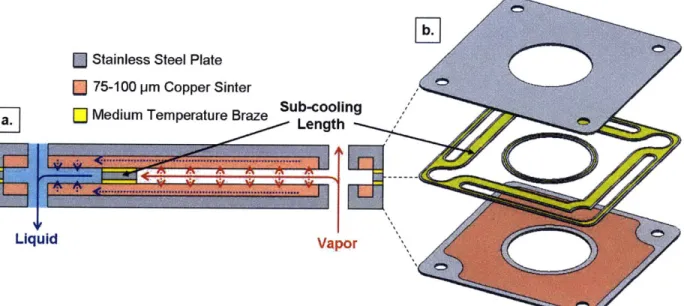
Stainless Steel Plate
75-100 pm Copper Sinter
Medium Temperature Braze Sub-cooling Length
EFiII
'C0
mm)Liquid Vapor
Fig. 2-5 (a.) Schematic showing a cross-section of the current condenser design and the flow path of the working fluid. (b.) 3D exploded view of the condenser to relate the cross-section to the physical design.
The parallel orientation of the condensers and the performance demands of the heat exchanger resulted in a condenser design of its current form. The condensers are fabricated from stainless steel plates to ensure structural rigidity and flatness of the thin parallel layers. Copper sinter is lined along the entire interior surface to facilitate
uniform condensation upstream of the sub-cooling section. This even condensation results in an isothermal surface over a majority of the condenser maximizing the heat transfer to the air. Although both stainless steel and the copper wick have low thermal conductivity on the order of 15 W/mK, the thin layers result in a low temperature
between the vapor space and the condenser surface. Copper sinter in the range of 75-100 pm was used in the condensers for maintaining high permeability and a maximum
capillary pressure of 5.6 kPa when operated with a receding meniscus. The receding meniscus set by the compensation chamber is key for preventing flooding of the lower condenser layers with wicks of this pore size due to the 1 kPa gravity head of a 10 cm column of liquid. To prevent re-vaporization of the liquid as it exits the wick into the liquid line, a 7 mm long sub-cooling section was added to the condenser. The section was sized such that the balance of temperature drop due to sensible heat and pressure drop from forcing flow through the wick result in a sub-cooled liquid state at the end of the condenser. Additionally, the pressure drop through the sub-cooling section
effectively acts as a flow restrictor to ensure even mass flow distribution into each condenser layer. Essentially, as long as the pressure drops within the condenser exceed the pressure drops due to gravity and the viscous losses in the vapor and liquid pipes, the mass flow will be equal in each condenser. Even mass flow is desired so that the
potential for heat transfer to the air is maximized in each layer.
Current LHP Design Calculations
For the LHP to function properly, the primary wick must provide enough driving capillary pressure to overcome the sum of the pressure losses within the system. These
pressure drops are caused by viscous losses, body forces, and capillary interfaces in the evaporator, condenser, vapor line and liquid line.
AP >_AP + AP + AP (AP.1)
capmax evaporator vapor condenser liquid gravity(2. )
The capillary pressure of the primary wick is determined by the Young-Laplace equation (2.2) as a function of wick effective pore radius (reff), the wetting contact angle of fluid on the wick (0), and the working fluid surface tension (u).
Aa,max 2 cos receding (2.2)
ref
The contact angle of the working fluid on a certain wick material can vary within a range of values from a minimum receding angle (Oreceding) to a maximum advancing angle. The wick will operate at maximum capillary pressure with a receding contact angle.
For flows through open channels, such as the liquid and vapor pipes, the viscous pressure drop can be calculated with the Darcy-Weisbach equation:
AP =
f
2(2.3)The equation is a function of Darcy friction factor (f), flow length (L), hydraulic diameter (Dh), density (p) and flow velocity (v). The hydraulic diameter can be calculated, for a circular pipe, as the diameter (Dh=D) or, for a rectangular pipe with side lengths a and b, as 4 times the area over the perimeter also written as
2ab
Dh = (2.4)
a +b
The mass flow rate ( i) circulating inside the heat pipe is generated by phase-change of the working fluid due to heat input into the evaporator. For the 1000 W known heat input
(Q) and working fluid heat of vaporization (hfg), the total mass flow is defined as ,= Q /
hfg. If there are multiple (N) channels, the mass flow rate per channel is defined as
h =
Q
/ Nhfg. The flow velocity (v) is determined from the mass flow rate as a function of the density (p) and the channel cross sectional area (A) as v = rh / pA. The Reynoldsnumber as a function of hydraulic diameter for the open channel flow is calculated as the following where the working fluid viscosity is pi:
ReD
pvDh
QDh (2.5)p1 Nhfg A p
For turbulent flow (Re > 2300), the friction factor can be calculated using [25]:
f
=(0.79
1n(Re 'h)-1.64)-2
(2.6) For laminar flow (Re < 2300) through a circular pipe, the friction factor can be calculated as f= 64 / Re. Using this correlation and the velocity definition, Eqn. 2.3 can bemodified into the Hagen-Poiseuille equation:
APD= = P28DuNhf (2.7)
p icD4 p irD 4 Nhfg
For laminar, fully developed flow in rectangular ducts with an aspect ratio a = b / a, the friction factor can be approximated as [17] :
f
=(1
-1.3553a+1.9467a2 -1.7012a3 + 0.9564a4 - 0.2537a)= 240 (2.8)Re Dh
Re Dh For laminar flow in rectangular ducts, Eqn. 2.3 can be rewritten using the definition of velocity and the friction factor as:
AP= 124LQ (2.9)
For flow through porous media such as sintered wicks, the pressure drop is calculated by Darcy's Law as a function of fluid viscosity (pi), fluid density (p), flow length (L), wick cross sectional area (A) and wick permeability (K):
p/Lv puLrh pLQ
AP= = = L(2.10)
K pAK pAKNh
For sintered wicks formed from unconsolidated, packed, spherical particles, the permeability can be estimated using [6]:
K= D2( 3
(2.11)
150 (1 - p)2
The equation is a function of average particle diameter (D) and wick porosity (<p). The porosity is the ratio of pore volume to total wick volume.
The pressure drops for the entire LHP can be estimated analytically using the aforementioned equations, working fluid properties, and the current geometry. Starting with the wick interfaces, the driving pressure from the primary wick in the evaporator (APeap) and the capillary pressure maintaining phase separation in the condenser (APeap,c) can both be calculated using Eqn. 2.2. For sintered wicks formed from unconsolidated, packed, spherical particles, the effective pore radius can be approximated as a function of
the average particle diameter (D) by reff= 0.21D [6]. For the evaporator wick, the sinter particle size ranges from 5-15 pm with an average D = 10 pm resulting in reff= 2.1 pm.
For the condenser wick, the sinter particle size ranges from 75-100 pm with an average D = 88 pm and rff= 18.5 pm. For 80 'C saturated water on copper sinter, the surface tension (a) is given in Table 2-2 and the receding contact angle (Oreceding) is 350 [6]. Therefore, the APeap= 48.9 kPa and APcap,c = 5.6 kPa.
Table 2-2 Properties of saturated water at 80 'C [24].
Liquid Vapor Liquid Vapor Surface Liquid Tsat Psat Density Density Heat of Vapor. Viscosity Viscosity Tension (C) (kPa) (kg/m3) (kg/M3) (kJ/kg) (pPa-s) (pPa-s) (mN/m)
Water 80 47.414 971.77 0.29367 2308 354.33 11.592 62.673
When heat is input at the base of the evaporator, the working fluid evaporates at the surface of the primary wick and that vapor flows through channels in the copper base plate to the vapor pipes. As shown in Fig. 2-6, the current base plate design has 14 channels total; 7 channels (M) connected to each of the 2 vapor pipes (V). The vapor channels are approximated as ducts with a square cross section, 2 mm width (a) by 2 mm depth (b), and average length (L) of 70 mm. The hydraulic diameter (Dh) is 2 mm using Eqn. 2.4 and the aspect ratio (a) is 1. Using Eqn. 2.5, N = M*V, and the vapor viscosity (Rv) and heat of vaporization (hfg) from Table 2-2, the Reynolds number (Re) is
calculated as 1335 which corresponds to laminar flow. Using Eqn. 2.8, the friction factor (f) is calculated as 0.0107 with <D = 0.6. Finally using Eqn. 2.9 and vapor properties from Table 2-2, the pressure drop (APv,e) in the vapor channels is calculated to be 38 Pa.
width 2 mm depth 2 mmN length 70 mm
Fig. 2-6 Schematic of the evaporator copper base plate showing the 14 dimensioned vapor channels that lead to recesses for two vertical vapor pipes.
Once the vapor exits the base plate channels, it travels vertically through the 2 vapor pipes (N = V) and branches into each condenser layer. The vapor pipe is round
... ... ... . .... ... ... . ... .... ... . ... ... .. ....
with a diameter D = 6 mm and a length L = 100 mm to the topmost condenser. The Reynolds number is calculated using Eqn. 2.5 as 3966 indicating that the flow is
turbulent. The friction factor is calculated as 0.042 using Eqn. 2.6. Using Eqn. 2.3 and vapor properties from Table 2-2, the pressure drop (APv,v) in the vapor pipes is calculated to be 69 Pa.
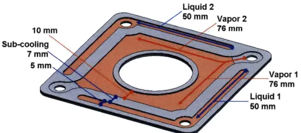
To maximize heat transfer from the condensers, the mass flow is assumed to divide evenly into each of the 15 condenser layers (C). As shown in Fig. 2-7, vapor enters the condenser from each of the 2 vapor pipes (V) and branches into 2 flow path (P) toward the outlet liquid pipes. The vapor channel has a 10 mm width (a), a 0.5 mm depth
(b), a 76 mm flow length (L), an aspect ratio (a) of 0.05 and a 0.952 mm hydraulic diameter (Dh) using Eqn. 2.4. Using Eqn. 2.5, N = V*C*P, and vapor properties from Table 2-2, the Reynolds number (Re) is calculated as 119 which corresponds to laminar flow. Using Eqn. 2.8, the friction factor (f) is calculated as 0.1895 with <D = 0.94. Finally using Eqn. 2.9 and vapor properties from Table 2-2, the pressure drop (APv,c) in the vapor channel of the condenser is calculated to be 54 Pa.
Liquid 2 50 MM Vapor 2 10 MM 76 mm Sub-cooling 7 mN 5 MM Vapor1I 76 mm Liquid 1 50 MM
Fig. 2-7 Schematic of the condenser plate interior showing vapor flow paths (red) and liquid flow paths (blue) along with channel dimensions.
A sub-cooling length is formed by brazing a stainless steel frame to the sinter surface between the vapor and liquid channels in the condenser. Due to the air-cooling on the exterior of the condenser, the vapor condenses onto the sinter wick under the vapor channel. To reach the liquid channel, the liquid flows through 10 mm under the vapor channel and a 7 mm sub-cooling length for a 17 mm flow length (L) of sinter wick with a
cross section (A) of 50 mm width (a) and 0.5 mm depth (b). The copper sinter has a particle size range from 75-100 pm with an average particle diameter (D) of 88 pm and
an assumed porosity (<p) of 0.4. Using Eqn. 2.11, the sinter permeability is estimated as K = 9.2 x 10~" m2. Appling Eqn. 2.10, N = V*C*P from earlier, and liquid properties from Table 2-2, the pressure drop (AP1,sub) sub-cooling pressure drop is calculated to be 195 Pa.
Past the sub-cooling section, the liquid channel consists of a stacked sinter layer and an open channel. Because the sinter layer will have high resistance, the liquid will preferentially flow through the open channel to exit out the liquid pipes. The open channel has a 5 mm width (a), 0.5 mm depth (b) and 50 mm flow length (L). The low flow rates combined with the open geometry result in a negligible pressure drop (AP1,c) of
less than 1 Pa.
The liquid flow recombines in the two liquid pipes (N=V) that connect the multiple condensers to the reservoir in the evaporator. The liquid pipes have a diameter (D) of 4 mm and a length (L) of 100 mm. The Reynolds number is calculated using Eqn. 2.5 as 195 indicating that the flow is laminar. Using Eqn. 2.7 and liquid properties from Table 2-2, the pressure drop (AP,I) in the liquid pipes is calculated to be ~1 Pa.
The reservoir in the evaporator keeps the backside of the primary wick
continually supplied with liquid as evaporation occurs on the opposite side. The reservoir can be approximated as an open flow channel with a 100 mm width (a), 3 mm depth (b), and 100 mm flow length (L). The low flow rates combined with the open geometry result in a negligible pressure drop (APi,r) of less than 1 Pa.
The primary wick in the evaporator is made from layers of stainless steel and copper sinter with a particle size ranging from 5-15 jim. Assuming an average particle diameter (D) of 10 [tm and a porosity ((p) of 0.4, the permeability can be calculated using Eqn. 2.11 as K = 1.19 x 10⁻¹³ M2. The liquid flows through the wick thickness such that
the area (A) is 100 mm by 100 mm and the flow length (L) is 4 mm. Applying Eqn. 2.10, N=1, and liquid properties from Table 2-2, the pressure drop (APi,,) for flow through the primary wick is 533 Pa.
The final pressure drop taken into consideration is gravity. Gravity head on columns of vapor is negligible due to the low density. However, if the 10 cm tall (L) device is oriented such that a gravity head acts in the flow direction on a column of liquid, the pressure drop can be calculated as APg = pigL = 953 Pa.
The total pressure drop (APtotai) is calculated by summing all of the pressure drops within the loop heat pipe. Referencing back to Eqn. 2.1, APevaporator= APv,e + API,r + API,w = 571 Pa, APvapor = APv,v = 69 Pa, APcondenser= APcap,c - APv,c - AP,sub + AP1,c = 5.8 kPa,
APliquid = API,1 ~ 1 Pa, and APgravity = APg = 953 Pa. Therefore, APtotal = 7.2 kPa which
uses only 15% of the available APcap = 48.9 kPa driving pressure with water as the working fluid. The large amount of pressure drop overhead allows for use of thinner
Working Fluid Comparison
To determine whether water was the best working fluid choice, five pure fluids (water, ammonia, methanol, acetone and ethanol) were considered that would allow the heat pipe to operate at 80 'C. Water has the highest surface tension (Y) at 0.062 N/m and heat of vaporization (hfg) at 2308 kJ/kg. However, water typically boils at 100 'C under
atmospheric pressure, therefore the heat pipe would have to operate at vacuum
conditions. The other working fluids boil at atmospheric pressure closer to the heat pipe operating temperature, but their lower heat of vaporization results in higher mass flow rates within the system. To analyze these tradeoffs, the pressure drops throughout the entire heat pipe were recalculated and compared for the different working fluids.
The detailed calculations from the previous section on the current LHP design with water were repeated, aided by a Matlab script, for the additional working fluids. The assumed properties for each fluid are given in Table 2-3 and the computed values for each pressure drop are displayed in Table 2-4. As shown in Fig. 2-8, the LHP design is not capillary pressure limited for any working fluid under consideration because APcap >
APtotal. Any of these working fluids could be functionally incorporated into the current design. However, while water only uses 15% of the available capillary pressure, the other working fluids require 25-35%. Therefore working fluids besides water would have less margin for redesign into geometries with higher pressure drops.
Fig. 2-9 shows the breakdown of the total pressure drop into each portion of the LHP. As shown in the previous section for water, liquid flow through the open channel in the condenser, liquid pipe, and reservoir contribute negligible pressure drop. The largest pressure drops occur due to the sintered wick in the evaporator and condenser. In
the evaporator, the pressure drop (API,,) is due to liquid flow through the homogeneous wick with a pore size dimensioned to achieve high capillary driving pressure. In the condenser, the pressure drop is due to both capillary pressure difference at the wick surface (APcap,c) and flow through the sinter under the sub-cooling length (APi,sub). Water has the largest capillary pressure drop in the condenser due to its high surface tension; ethanol has the highest pressure drops for flow through sinter due to its high liquid viscosity and low heat of vaporization that results in high mass flow rates.
Table 2-3 Properties of saturated fluids at 80 'C [24]. Receding contact angles are
approximate and referenced from [6].
Liquid Vapor Liquid Vapor Surface Theta Liquid Tsat Psat Density Density Heat of Vapor. Viscosity Viscosity Tension Receding
(*C) (Pa) (kg/m3) (kg/M3) (kJ/kg) (pPa-s) (pPa-s) (mN/m) (0)
Water 80 0.047414 971.77 0.29367 2308 354.33 11.592 62.673 35
Ammonia 80 4.142 505.67 33.888 873.97 77.98 11.954 9.614 35
Methanol 80 0.18111 732.58 2.1229 1069.2 274.24 11.265 17.573 25
Acetone 80 0.21548 719.79 4.6423 473.88 201.40 8.938 15.676 7
Ethanol 80 0.10857 734.64 1.7591 846.97 429.47 10.431 15.030 7
Table 2-4 Matrix comparison of pressure drops throughout the working fluids. The pressure drops are given in Pa.
LHP for 5different
APcap APtotal APcap,c APv,e APv,v APv,c API,sub API,c API,I API,r API,w APg Water 48894.0 7205.4 5556.1 38.0 69.1 53.6 195.1 0.7 1.3 0.0 533.2 953.3 Ammonia 7500.5 1951.4 852.3 0.9 3.2 1.3 217.9 0.8 1.4 0.0 595.5 496.1 Methanol 15168.1 3690.2 1723.7 11.0 35.0 15.6 432.4 1.5 2.8 0.0 1181.9 718.7 Acetone 14818.2 4473.6 1683.9 9.0 61.8 12.8 729.1 2.5 4.7 0.1 1992.8 706.1 Ethanol 14207.6 4772.6 1614.5 15.6 61.8 22.0 852.3 2.9 5.5 0.1 2329.5 720.7
50 40 m Water o Ammonia 2 3 Methanol o30 m Acetone U) U) Ethanol c. 20 10 0
Capillary Driving Total Viscous
Pressure Losses
Fig. 2-8 Bar graph showing comparison of capillary driving pressure to the total viscous (and gravity) losses within the LHP for 5 different working fluids. Although APeap exceeds APtotal in all cases, water has the largest margin.
6000 5000 4000 W L 0 Water a- 0 Ammonia 3000 0 Methanol N Acetone 0 Ethanol L 2000 1000 0
APcap,c APv,e APv,v APv,c API,sub API,c API,1 APIr API,w
Fig. 2-9 Bar graphing showing individual pressure drops comprising APtotal for 5 different working fluids. In all cases, flow through sinter in the sub-cooling length
(API,sub) and the primary wick (APi,w) and the capillary interface in the condenser (APeap,c)
contribute the largest pressure drops.
£
C
C
... ... ... . ... .... ... ...
Sintered Wick vs. Open Channel in Condenser
The calculations thus far have proven that the capillary driving pressure exceeds the pressure drops due to the addition of sinter in the condensers. This section will investigate whether that sinter is needed for flow stability of the parallel condensers. As stated in the design section, sinter was incorporated into the condensers to create a stable separation of phases. When gravity acts in the same direction as flow through the liquid pipe, a pressure rise is created between the top and bottom condensers. If the gravity head sets a pressure exceeding the pressure drop within the layer, the bottom condenser will experience high pressure at the outlet and low pressure at the inlet causing flow reversal and flooding of the layer.
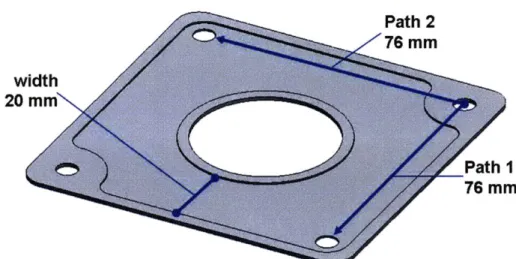
To better understand the role of sinter, the current LHP design was compared to a design with an open channel condenser, shown in Fig. 2-10. In each of the 15 layers (C), vapor enters from the 2 vapor pipes (V), branches into 2 flow paths (P) and condenses as
during flow to the liquid pipes. For these calculations, the two-phase flow is
approximated as separate vapor and liquid flows, each for half the flow length, and a capillary interface between the phases. The open channel has a 20 mm width (a), 1.5 mm depth (b), 76 mm total flow length (L), 2.8 mm hydraulic diameter (Dh), and aspect ratio of 0.075. The flow is assumed to be laminar for both phases due to the slow flow rates and open geometry in each layer. Applying Eqn. 2.9 and vapor properties from Table 2.2, the pressure drop due to vapor flow (APv,c) is ~ 0.5 Pa. Applying Eqn. 2.9 and liquid properties from Table 2.2, the pressure drop due to liquid flow (AP1,c) is << 1 Pa. Finally,
assuming a receding contact angle (ereceding) of 350 and an effective radius (reff) equal to the 1.5 mm channel depth.
Path 2 Z76 mm width 20 mm Path 1 76 mm
Fig. 2-10 Schematic of open channel condenser showing flow paths and dimensions. The absolute pressure can be mapped for each design given a known starting pressure and the pressure drops within each segment of the loop. The starting pressure at
the evaporation interface of the primary wick is assumed to be the 47.4 kPa saturation condition (Psat) for water at 80 *C. To form the graph in Fig. 2-11, pressures are
calculated at each point P1 thru P4 by subtracting pressure drops over that portion of the
LHP from the absolute pressure and these points are connected with a smooth fit curve. To graph the blue vapor curve from left to right, the following equations are used along with the pressure drops for water in Table 2-4:
P 1,vapor = Psat P2,vapor P1 ,vapor - APv,e P3,vapor - P2,vapor - APv,v
P4,vapor P3,vapor - Apy,c
To graph the pink liquid curves from right to left, the following equations are used along with the pressure drops for water in Table 2-4 and the open channel calculations from above:
.. ... ... .. ... ...
P4,liquid P4,vapor - APcap,c
P3,liquid - P4,liquid - AP1,sub - APl,c (sinter) P3,liquid = P4,liquid -AP1,c (open) P2,Iiquid P3,liquid - API,1 + APg (gravity) P2,liquid P3,fiquid - AP1,1 (no gravity)
P1,liquid P2,liquid - AP,r - API,w
The graph in Fig. 2-11 shows that the largest pressure drops due to gravity (APg) and the capillary interface in the condenser (APcap,c) heavily influence the pressure profile inside the LHP. The blue vapor curve is fairly flat because the pressure drops due to vapor flow never exceed 160 Pa. The solid pink curve for the current LHP design with sinter but neglecting the influence of gravity shows a substantial pressure jump across the condenser wick interface and then a gently decreasing pressure from right to left due primarily to viscous drops from flow through the two sinter wicks. In contrast when gravity head is applied to the liquid pipe, the design with sinter and the open channel (no
sinter) both experience a pressure rise between P3 and P2. In the open channel, that
pressure rise causes the liquid pressures (pink dotted line) to cross above the vapor pressures. The flow in the lower condensers will go from the high pressure liquid to the lower pressure vapor causing flooding of the condenser layer. However, in the case of the design with sinter, the capillary pressure drop substantially reduces the liquid pressures such that the gravity rise will increase pressure but maintain the correct circulation inside the LHP.
These results indicate that a pressure drop exceeding the gravitational pressure rise is required within the condenser and liquid pipe to prevent flooding of the lower parallel layers. Within the current LHP design, the sinter interface in the condenser creates a large enough pressure drop to ensure stable circulation of the working fluid through all layers.
; - - - - - - - - - - Vapor IL 046-APcap,c
E
44 - Sinter sinter MGravityite =42 - Liquid 0 40- Sinter No Gravity 38P1 Evaporator P2 Adiabatic Pipes P3 Condenser P4
Fig. 2-11 Graph showing absolute pressure versus location in the heat pipe. The open channel (no sinter) case will experience flooding because the liquid pressure is higher than the vapor pressure. In contrast, the capillary interface at the sinter surface creates a large enough pressure drop to prevent cross-over of the liquid and vapor pressures.
Mass Flow Balance
The previous section determined that a pressure drop exceeding the gravitational head is needed to prevent flooding of the lower condensers. That pressure drop can occur interchangeably within the condenser or the liquid pipe to satisfy the stable flow criteria. This section will investigate whether the location of that pressure drop affects mass flow balance between each of the parallel condensers. As stated in the design section, the open geometry of the vapor channel and liquid pipe and the high pressure drop geometry of the capillary interface and sub-cooling section are all intended to ensure equal mass flow in each condenser layer.
A Matlab model was developed to explore the sensitivity of mass flow
distribution to magnitudes and locations of pressure drops within the vertical pipes and condenser layers. The code for this Matlab model is provided in Appendix A. As shown
in Fig. 2-12, the model represents the heat pipe as a network of resistors and capacitors. Given an input total amount of mass flow along with known flow resistances and
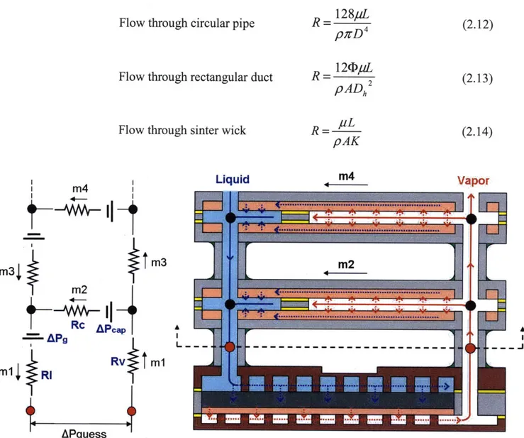
constant pressure effects, the model solves for mass flow through each parallel condenser and pressure drop for this portion of the heat pipe. The resistances represent viscous losses in the system due to vapor or liquid flow. The capacitors represent pressure drops due to capillary interfaces and pressure rises due to gravity head. Assuming laminar flow throughout the system, the resistances are defined in the following manner:
128pL (.2
Flow through circular pipe R = 4 (2.12)
Flow through rectangular duct R = 2 (2.13)
pADh
Flow through sinter wick R - pL (2.14)
pAK Liquid m4 Vapor m4
m3
m2
m 3j m2m2J
AAcT
APguessFig. 2-12 Schematic of resistor and capacitor network used to model the parallel condenser plates and vertical fluid lines.
---The total flow resistance through the vapor pipe (Rvtotal) is calculated using Eqn. 2.12 and the water vapor properties given in Table 2-2. Both open and sinter filled liquid pipes are explored with this model, therefore either Eqn. 2.12 or Eqn. 2.14 is used along with the liquid properties in Table 2-2 to calculate total flow resistance through the liquid pipe (Rltotal). Both Rvtotai and Rltotai are calculated for the full 100 mm pipe length. The resistance for flow through each segment connecting the "n" number of parallel
condensers is therefore Rv = Rvtotal / n and R1= Rltotai / n. In essence, the model assumes that the LHP will take up the full 100 mm allocated height regardless of the number of condensers. The total flow resistance of the condenser (Rc) is calculated by summing the resistance from flow through the vapor space using Eqn. 2.13 and liquid flow through the sinter wick using Eqn. 2.14. The total pressure drop due to gravity is always 968 Pa assuming a 100 mm gravity head, therefore the gravity head applied to each segment connecting the "n" number of parallel condensers is APg = 968 / n. Finally, the capillary pressure at the condenser wick interface (APcap) is assumed to be constant and equal in every condenser layer and is calculated using Eqn. 2.2 for the sinter composition.
Given a known input mass flow (ml) and an initial estimate of total pressure drop (APguess), the model solves for the mass flow in every segment of the loop and pressure at every branching node. Mass flow must be conserved at every node within the system e.g. ml = m2 + m3. In the top most layer of the condenser stack, the mass flow through the condenser equals the mass flow in the liquid and vapor pipes. For example, if the maximum number of condensers is 2 as shown in Fig 2-13(a), m3 = m4. Within the parallel condenser structure, every flow path must result in the same ultimate pressure
drop (APguess) across the network. As shown in Fig. 2-13(a), the following equations must be equal:
Path 1 APges, = m1(Rv + Rl)+ m2(Rc)+ APap - APg (2.15)
Path 2 APgues, = (ml + m3)(Rv + R1) + m4(Rc) + APcap - 2(APg) (2.16)
Of course, the number of equations will increase directly with the number of condensers. The actual solving scheme is modeled after the loops shown in Fig. 2-13(b). Loop 1 is represented by Eqn. 2.15. Loop 2 is represented by:
m3(Rv + R1) + (m4 - m2)(Rc) = AP (2.17)
For any Loop n within the network, Eqn. 2.17 can be written more generally as:
m2n-1 (Rv + R1) + (m2n - m2n-2)(Rc) = AP (2.18) The model iterates the value of APguess until the system of equations for conserved mass flow and loop pressure drop are satisfied. The model solves for mass flow within each
segment of the network for n = 2 to 18 condensers and pressure drop for the entire flow loop.
a.
m4
m4
0 V I 4-AY
m~l
m33
Path 2 mm3j
l OLoop 2 2tm mm2 m2
Rc APcap
APRc APa
ml R IPath i IRV M1 M1 ILoop I Rv M m1
m
RI
m15
R1
APguess
APguess
Fig. 2-13 Schematic of resistor network illustrating methods of solving within the
Matlab code. (a) Flow paths beginning and ending at the same points must have the same pressure drop. Additionally, mass flow is conserved at every node. (b) Given an initial
guess of pressure drop and input mass flow, the code solves each loop and iterates APguess
until constraints in (a) are satisfied.
The following calculations were performed for an earlier iteration of the loop heat pipe design. That iteration had sinter in the condenser and liquid pipe, no sub-cooling length, and assumed 100 mm length of liquid flow through the wick between
condensation and the outlet port. Although the geometries are different, the conclusions from this model helped guide the current design and therefore the modeling results are shown here. The model under initial evaluation had the following conditions, with high resistance in both the condenser layer and the liquid pipe:
Rv 1.2594 x 10'
Rc 2.0632 x 10⁸ RI 1.3102 x 10⁸ APcap 2177
As shown in the graph in Fig. 2-14, this geometry experiences high mass flow through the lowest condenser layers and low mass flow through the higher layers. This indicates that a large viscous pressure drop is required through the bottom condenser to balance pressure drops through the vertical pipes. The capillary pressure (APcap) was varied from 0 to 50,000 with all other parameters held constant. Although the total pressure drop increased, the mass flow subdivided in the same manner as shown in Fig. 2-14. Therefore, while the capillary pressure was shown to prevent flooding in the previous analysis, this study suggests that only viscous flow resistances affect flow distribution.
0.14 0.12 total # condensers 0.1 - 2 .4 008 . 6 x8 0.06 X10 X ,.12 0.04 +14 -16 0.02 -18 0 0 2 4 6 8 10 12 14 16 18 20 Condenser Number
Fig. 2-14 Graph of mass flow rate within each condenser layer. Data shows trends of high mass flow through bottom condensers and low mass flow through high level ones.
To study the effect of the viscous resistance location, another version of the model was solved with a reduction in condenser resistance by one order of magnitude such that Rc = 2.0632 x 10⁷ and all other parameters held the same. As shown in Fig. 2-15, the data again shows unbalanced flow rates within the condensers. Compared to Fig. 2-14,
...
this data shows an even steeper drop off in mass flow suggesting that high liquid pipe resistance with low condenser resistance will always result in unbalanced flow.
0.18 0.16 total # 0.14 condensers 1 4 0.12 -4 6 a 0.1 + o 0.08 X10 L .12 0.06 cc +14 0.04 -16 ~0.02 0.02 -18 0-0 2 4 6 8 10 12 14 16 18 20 Condenser Number
Fig. 2-15 Graph of mass flow rate within each condenser for reduced condenser resistance.
To test the reverse scenario, this time the liquid pipe resistance was reduced by one order of magnitude to RI = 1.3102 x 10⁷ with all other parameters held constant from the initial model. As shown in Fig. 2-16, the mass flow per condenser forms
approximately a horizontal line indicating that flow is balanced. These results suggest that high condenser flow resistance with low liquid pipe resistance creates even mass flow. To further investigate this conclusion, the liquid pipe resistance was further reduced by 4 orders of magnitude to RI = 1.3102 x 10³. As shown in Fig. 2-17, the data still shows a slightly increasing, but still horizontal trend supporting a design with very low liquid pipe resistance, which can be achieved using open pipe geometry.
In conclusion, the Matlab model showed that high flow resistance in the condenser combined with low resistance in the liquid pipe resulted in balance flow
between the condenser layers. These results support the use of sinter and a sub-cooling length in the condensers to create a high pressure drop flow restriction.
0.12 0.1 0.08 0.06 0.04 0.02 0 2 4 6 8 10 12 14 16 18 2 total # condensers +2 "4 6 x 8 x10 * 12 + 14 -16 - 18 0 Condenser Number
Fig. 2-16 Graph of mass flow rate within each condenser for reduced liquid pipe
resistance. Data for each number of condensers is almost horizontal suggesting that flow is balanced between the layers.
0.12 0.1 0.08 0.06 0.04 0.02 0 x X X X x X x x 0 2 4 6 8 10 12 14 16 18 21 total # condensers + 2 . 4 6 x 8 * 10 * 12 + 14 -16 - 18 Condenser Number
Fig. 2-17 Graph of mass flow rate within each condenser for very low liquid pipe resistance. Data suggests that even open geometry liquid pipe could be used in design.
+ +
* U * U
x x x x x x x x
Chapter 3: Working Fluid Deaeration
Overview
Within the heat pipe evaporator, gases dissolved in the working fluid are released during phase change to vapor. These gases travel with the vapor to the condensers where they accumulate, effectively blocking off area from vapor condensation. Three different methods of deaeration were investigated as a means of removing dissolved
non-condensables from the water prior to use as the working fluid in a condensing flow test setup or the heat pipe design. Vacuum degassing, helium sparging, and freeze-pump-thaw cycles were performed on containers of DI water and their results were qualitatively validated via condensing flow experimental testing. The freeze-pump-thaw method turned out to be the most effective at removing non-condensable gases owing to the small container volume, ability to pull down to low vacuum, and direct use as the vapor
generation tank in the experimental setup.
Vacuum Degassing
Concept
Vacuum degassing is a technique where vacuum pumping is used on a tank of liquid to remove dissolved non-condensable gases. Fig. 3-1 shows the solubility of 02 and N2, the main components of air, in room temperature water as a function of pressure. The vacuum pump removes gases in the vapor space above the water that is being
degassed. The saturation pressure of water at 25 'C is 0.031 atm [24], so initially the gas that is removed is mostly air. At atmospheric pressure, 0.009 g of 02 and 0.011 g of N2 are soluble in one liter of water. As the pressure above the water is decreased by the
vacuum pump, the amount of 02 and N2 soluble in the water decreases, so 02 and N2 must come out of solution. The 02 and N2 diffuse to the water surface where the
dissolved gas concentration is the lowest and the gases are then removed by the vacuum pump. As the pressure approaches 0.031 atm (saturation pressure of water at 25 'C), the solubility of both N2 and O2 decrease below 0.001 g/L and water vaporization increases.
0.016 0.014 ID 0.012 -0 0.010 -- 02 o~ 0008--N2 a 0.006-0.004 5& 0.004-0.002 0.000 0 0.1 0.2 0.3 0.4 0.5 0.6 0.7 0.8 0.9 1 Pressure (atm)
Fig. 3-1 Graph of solubility of oxygen and nitrogen in room temperature water as a function of pressure. Based on Henry's Law, solubility decreases with decreasing
pressure. The Henry's law constants used for this plot were 769.23 L.atm/mol for 02 and 1639.34 L.atm/mol for N2 [17].
Equipment
The water used in the deaeration is ACS Reagent Grade, ASTM Type I deionized, double distilled water (RC91501, Ricca Chemical). Approximately 2.5 gallons of water are poured directly into a 3 gallon capacity, stainless steel pressure vessel (41705K42, McMaster) that acts as the vapor generation tank in the experimental setup. A schematic of the setup for vacuum degassing is shown in Fig. 3-2. The tank is connected to a port with a ball valve via 12" of %" diameter stainless steel tubing. The vacuum pump and a liquid nitrogen trap are then attached to the port with 1/2" diameter flexible plastic tubing.
The vacuum pump used for degassing is a two-stage, belt-driven high vacuum pump
(1402, Welch) capable of an ultimate pressure of 0.1 mTorr as shown on the performance
curve in Fig. 3-3. The liquid nitrogen trap (CG-4515, Chemglass) is located upstream of the pump with its body immersed in a dewar of liquid nitrogen to prevent vapor from reaching the vacuum pump. A thermocouple vacuum sensor (DV-6M, Teledyne
Hastings) with a 1 - 1000 gHg range analog vacuum gauge (VT-6A, Teledyne Hastings) is located between the trap and the vacuum pump. This placement of the vacuum
pressure sensor prevents water damage to the sensor, but it should be noted that the sensor measures the pressure with the condensable vapors removed by the nitrogen trap, which is a lower pressure than the actual pressure in the water tank.
Glass
Valve Nitrogen Trap Vacuum Gauge
Dl Water in Liquid Nitrogen Welch 1402
Steel Tank Dewar Vacuum Pump


![Fig. 3-3 Pump performance curve for Welch 1402 vacuum pump with an ultimate pressure of 0.1 mTorr and a maximum pumping speed of 5.6 cfim (mTorr = pHg) [19].](https://thumb-eu.123doks.com/thumbv2/123doknet/14687964.560601/45.918.229.693.127.442/pump-performance-welch-vacuum-ultimate-pressure-maximum-pumping.webp)
