Design of a mechanical clutch-based needle-insertion device
The MIT Faculty has made this article openly available.
Please share
how this access benefits you. Your story matters.
Citation
Bassett, Erik K et al. “Design of a mechanical clutch-based
needle-insertion device.” Proceedings of the National Academy of Sciences
106.14 (2009): 5540-5545.
As Published
http://dx.doi.org/10.1073/pnas.0808274106
Publisher
National Academy of Sciences
Version
Final published version
Citable link
http://hdl.handle.net/1721.1/50261
Terms of Use
Article is made available in accordance with the publisher's
policy and may be subject to US copyright law. Please refer to the
publisher's site for terms of use.
Design of a mechanical clutch-based
needle-insertion device
Erik K. Bassetta,1, Alexander H. Slocuma, Peter T. Masiakosb,c, Howard I. Pryor IIb,d, Omid C. Farokhzadb,e,
and Jeffery M. Karpb,f,g,2
aDepartment of Mechanical Engineering,fHarvard–MIT Division of Health Science and Technology, andgMassachusetts Institute of Technology, Center for Biomedical Engineering, Brigham and Women’s Hospital, Cambridge, MA 02139;bHarvard Medical School, Boston, MA 02115;eDepartment of Anesthesia, Brigham and Women’s Hospital, Boston, MA 02115; andcDepartment of Pediatric Surgery anddCenter for Regenerative Medicine, Massachusetts General Hospital, Boston, MA 02114
Edited by Robert Langer, Massachusetts Institute of Technology, Cambridge, MA, and approved February 11, 2009 (received for review August 25, 2008)
Insertion of trocars, needles, and catheters into unintended tissues or tissue compartments results in hundreds of thousands of com-plications annually. Current methods for blood vessel cannulation or epidural, chest tube, and initial trocar placement often involve the blind pass of a needle through several layers of tissue and generally rely on distinguishable anatomic landmarks and a high degree of clinical skill. To address this simply and without the use of electronics, a purely mechanical clutch system was developed for use in medical devices that access tissue and tissue compart-ments. This clutch utilizes the surface contact of a buckled filament inside an S-shaped tube to transmit force from the filament (catheter/guide wire) to the tube (needle). Upon encountering sufficient resistance at the tip, such as dense tissue, the catheter buckles and locks within the tube, causing the filament and needle to advance as one. When the needle reaches the target tissue or fluid-filled cavity, the filament unlocks and slides freely into the target region while the needle remains stationary. A similar locking phenomenon has long been observed in drill strings inside drill shafts used by the oil-drilling industry, and oil industry models were adapted to describe the motion of this clutch system. A predictive analytical model was generated and validated with empirical data and used to develop prototypes of a complete device then tested in vitro on muscle tissue and in vivo on a porcine laparoscopic model with promising results.
catheter兩 helical-buckling 兩 trocar
I
mproperly inserted and positioned needles and catheters often require repeated attempts to achieve correct placement, caus-ing mechanical injury to adjacent tissues or misdirected drug infusion. The associated complications include discomfort from repeated insertion attempts, bleeding, postdural puncture head-ache, nerve injury, hemodynamic shock, and respiratory arrest (1). Approximately 75,000 inadvertent punctures of the sub-arachnoid space occur annually in the U.S. alone (2). With the growing problem of obesity, the skto-target distance is in-creasingly variable, and important anatomical landmarks are more difficult to recognize (3). This can result in slower proce-dure times and the need for greater operative skill.Current techniques for accessing specific regions of the body with needles, catheters, and trocars typically involve blind guid-ance where the physician or nurse relies entirely on tactile feedback, experience, superficial anatomical landmarks, and fluid return through the instrument. The operator must sense when the needle (or trocar) enters the target space and discon-tinue advancement. However, existing needle systems often do not provide sufficient feedback to the physician to indicate correct positioning.
Current devices like Veress needles and certain trocars at-tempt to address these problems with spring-loaded blade sheathes or retractable blades. In both cases, these intended safety features do not always prevent damage to underlying organs (4). Accordingly, the FDA published a report in 2003
regarding laparoscopic procedures stating that most complica-tions occur at initial trocar insertion and stressed the need for medical device companies to improve their products (5).
In addition to spring-loaded devices, a variety of guidance and sensing-based systems have been developed to improve targeted placement of needles and trocars. Examples include ultrasound and active sensing systems on the tips of needles. Although ultrasound guidance can be useful, there are situations where it is inconvenient, does not provide the required resolution, or simply cannot be used.
Over the past 4 decades, only minor improvements to cathe-terization procedures, such as epidural placement, have been achieved (6). Accordingly, the goal of this work was to develop a reliable, inexpensive, simple, nonelectric automatic clutch system that automatically disengages upon a specific change in tissue resistance for potential use in a variety of common medical procedures including catheterization, laparoscopy, tracheotomy, and placement of chest tubes.
This work initially focused on generating an analytical model for engagement of an automatic mechanical clutch for a needle device using empirical data from a tension/compression testing machine. Next we studied the engagement and disengagement of the clutch upon entering and exiting tissue. Empirical and analytical tools were used with an iterative optimization process to finally develop a functional working prototype that was successfully tested within an animal model.
Description of the Mechanical Clutch
To create a device that mechanically detects when a needle passes from a high-resistance tissue region into a low-resistance region, we have taken advantage of 2 mechanical effects: buck-ling and a capstan-like effect. Specifically, a simple mechanical clutch was developed based on the sliding resistance of a flexible filament (such as a catheter or guide wire) within a constant-diameter S-shaped tube. A sufficient compressive force along the filament axis causes it to buckle and lock inside the tube (Fig. 1). The S-shape causes the filament to buckle at a lower compressive force and, by acting like a capstan, wedges and locks the filament in place. A sufficiently high coefficient of friction can cause the filament to rapidly lock (or jam) inside the tube when com-pressed. Once locked, an increase in compressive force applied
Author contributions: E.K.B., A.H.S., P.T.M., O.C.F., and J.M.K. designed research; E.K.B. and H.I.P. performed research; E.K.B. contributed new reagents/analytic tools; E.K.B., A.H.S., and J.M.K. analyzed data; and E.K.B., A.H.S., P.T.M., H.IP., O.C.F., and J.M.K. wrote the paper.
The authors declare no conflict of interest. This article is a PNAS Direct Submission.
1To whom correspondence may be addressed at: Massachusetts General Hospital, 55 Fruit
Street, Boston, MA 02114. E-mail: [email protected].
2To whom correspondence may be addressed at: Harvard Medical School Room 313, PRB,
65 Landsdowne Street, Cambridge, MA, 02139. E-mail: [email protected].
This article contains supporting information online atwww.pnas.org/cgi/content/full/
to the filament is transferred to the tube, causing the tube (needle) and filament to advance together as one. The moment that the needle breaks through into a lower-resistance tissue or open cavity, such as the lumen of the vessel or epidural space, the opposing force of the tissue on the tip of the filament rapidly drops, the filament unbuckles, and the needle no longer ad-vances. In other words, when the filament unbuckles, it can no longer transmit force to the needle so the needle stops advanc-ing. These series of events are possible because there is no direct force being applied to the needle; direct force is applied only by the operator to the filament (wire or catheter). In addition to automatically stopping within the target tissue or cavity, this system may be useful for a one-step rapid insertion of a guide wire or catheter, which may significantly reduce the time of these procedures. Because the tissue resistance is application-specific, the behavior of the device can be tuned for specific applications. The locking action of the clutch in S-shaped tubes was modeled with nylon or PTFE filaments inside steel tubes using a tension/compression-testing machine [supporting information (SI) Fig. S1]. Using this machine, we applied a force to the input side of the filament while measuring the force at the output (Fig. S2). Ten and 23 S-tube shapes with differing design parameters were tested with nylon and PTFE filaments, respectively (Tables S1andS2). The design parameters included number of bends, average bend radius, and arc length of bends (Fig. S4). An analytical model including these parameters was generated to predict the behavior of the clutch system during development and to iterate toward a functional prototype.
Analytical Model for Predicting Engagement/Disengagement of the Clutch
Insight for an analytical model was drawn from oil-well drill strings used in the petroleum industry. Drill strings are often in
compression and have the tendency to buckle and ‘‘lock’’ (jam) inside the well if the compressive load exceeds a critical threshold (7). This critical locking point depends on the buckling point of the drill string and length and shape (curvature and number of curves) of the drill hole. Extensive work has been performed to model and predict buckling and frictional drag of the drill string in the drill hole (8). Previously described analytical models for drill strings created the basis for our model to predict the compressive forces in the filament and its locking point. Specif-ically, Eqs. 1 and 2 were derived by He and Kyllingstad to predict the normal contact forces between the drill string and the well wall (9).
F1hbc⫽
Fa2r
4EI [1]
F1nbc⫽ 关共fbmgsin ⫹ Faai兲2⫹ 共Faasin兲2兴5. [2]
Eq. 1 applies to a helically buckled drill string in a straight well. It was assumed (see Model Assumption Validations for validation) that the filaments in our systems always formed a helix when buckled. Eq. 2 applies to both straight and curved wells before buckling; however, in an unbuckled state, the contact force in the straight section would be negligible (Fig. 1 A and C). Removing all other negligible terms and approximating the inclination build rate (ai) as 1/R (for descriptions of approximation seeSI Text), Eq. 2 reduced to:
F1nbc⫽
Fin
R . [3]
With these simplifications, it becomes apparent that F1nbcand F1hbcrepresent the contact forces for the curved and straight
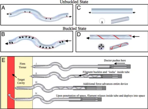
Fig. 1. Unbuckled and buckled flexible filaments within an S-shaped and straight tube. (A and B) The segments of filament contacting the tube (contact length) that experience sliding resistance for an uncompressed (A) and compressed (B) filament are shown in red. (C) Negligible sliding resistance is experienced within a straight tube in an uncompressed state. (D) Under compression, the filament rapidly buckles into a helix within the straight tube (or straight extension of the S-tube). In the compressed buckled state, the contact length and sliding resistance increase. With sufficient friction, the filament locks or jams inside the tube when compressed. (E) Incorporation of these principles into a clutch-based medical device for accessing a tissue compartment. (Ei) The physician positions the needle tip at the desired point of entry/trajectory and applies force to a hand piece. (Eii) The blunt-ended filament, unable to penetrate the firm tissue, buckles and locks inside the needle (as shown in C and D). (Eiii) Additional force is transferred from the filament to the needle wall resulting in advancement of the needle (including the locked filament). (Eiv) Upon entering the target compartment, the filament automatically unbuckles and advances, and simultaneously the needle stop advancing.
Bassett et al. PNAS 兩 April 7, 2009 兩 vol. 106 兩 no. 14 兩 5541
ENGINEERING
APPLIED
BIOLOGICAL
segments of tubing respectively. To determine the frictional resistive force along the tube axis (sliding resistance), the contact forces of the filament on the tube, F1nbcand F1hbcwere multiplied
by the friction coefficient () and respective tubing segment lengths (L):
Fcontact㛭straight⫽LstraightF1hbc [4]
Fcontact㛭curved⫽Lcur vedF1nbc. [5]
In the curved regions of the tube, the filament transitions back and forth from one tube wall to the other as shown in Fig. 1 A and B. The transition segments (i.e., regions that are not in contact with the tube wall) were summed into a length term (Ltransition) that was
subtracted from Lcurved to get the true contact length of the
filament. The transition length depends not only on the filament diameter and the inner tube diameter but also on the applied compressive force, moment of inertia, and modulus of elasticity of the filament. To simplify this, Ltransitionwas approximated as the
transition length if the filament were unbuckled (Fig. 1 A) and, thus, would depend only on the filament diameter, radial clearance between the filament and tube i.d., and curvature of the tube as shown in Eq. 6 (this approximation is justified below in Model
Assumption Validations).
Fcontact㛭curved⫽共Lcur ved⫺ Ltransition兲F1nbc. [6]
Substituting Eqs. 2 and 3, respectively, into Eqs. 4 and 6 yields:
Fcontact㛭straight⫽L
straightFin2r
4EI [7]
Fcontact㛭curved⫽共L
cur ved⫺ Ltransition兲Fin
R . [8]
Finally, to obtain the resulting output force (Fout㛭predicted), the
contact forces (Fcontact㛭curvedand Fcontact㛭straight) were subtracted
from the applied input force (Fin):
Fout㛭predicted⫽ Fin⫺ 共Fcontact㛭curved⫹ Fcontact㛭straight兲. [9]
Substituting Eqs. 7 and 8 into Eq. 9 yields:
Fout㛭predicted⫽ Fin
⫺
冋
共Lcur ved⫺ Ltransition兲FinR ⫹
LstraightFin 2
r
4EI
册
. [10] As is common with idealized analytical models of mechanical systems, the predicted value amplitudes did not exactly match the measured compression test data. Instead, the predicted forces followed similar trends but were much larger than the measured forces. After further analysis of the contributions of each com-ponent of the equation and comparing with measured data,Fcontact㛭straightwas found to be the cause of the overprediction. As
with traditional buckled beam equations, a correction factor was required to align the trends with the empirical data. Without a correction factor, the analytical model could predict empirical trends but not the absolute values required for practical engi-neering applications. It was hypothesized that this correction factor might include a dimensionless constant (D/L) and a scaling factor (C). Before additional experimentation with the tension/compression-testing machine, the data were reanalyzed with the inclusion of the dimensionless constant to determine a suitable scaling factor. From this analysis of the empirical and model data, we determined that the scaling factor should be between 35 and 50. Inclusion of this factor significantly enhanced the accuracy of the model predictions. To study this further, and to determine how robust the addition of a dimensionless con-stant was to predict the empirical data, we chose to vary the length of the straight region of the S-tubes (tube shapes Cii–iv and Gii–iv inTables S1 and S2). Changing the straight segment length alters the number of helices that the filaments form and has a significant effect on the compressive force required to reach the lock point. With the newly generated empirical data, the scaling factor was further iterated to a final value of 40 to maximize the predictive accuracy of the model. Representative data from these tests are shown in Fig. 2. Using 40Dfilament/ Lstraightyielded:
Fout㛭predicted⫽ Fin
⫺
冋
共Lcur ved⫺ Ltransition兲FinR ⫹
10DfilamentFin2r
EI
册
. [11]To validate the analytical model for differences in the properties of the filament, PTFE and nylon filaments were used that
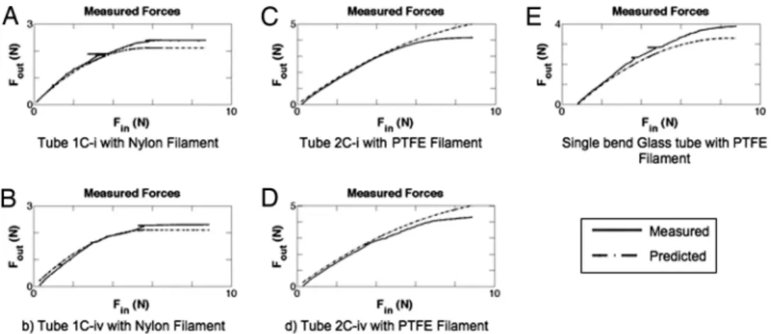
Fig. 2. Empirical compression test results (solid lines) with prediction (dashed lines). Finis the applied compressive force to the filament, whereas Foutis the measured force after passing through the tube. (A and B) Compressive forces in nylon filament for a single-bend S-tube with a long straight segment (A) and shortened straight segment (B). (C and D) Compressive forces in PTFE filament for a two-bend S-tube with a long straight segment (C) and shortened straight segment (D). (E) Compressive forces in a PTFE filament for a single-bend glass tube. The PTFE, being stiffer and having a lower friction coefficient, transmitted more force through the tube than the nylon. The locked regime (flat section of curves where Foutremains constant) for the nylon is visible in both the prediction and measured values in A and B.
differed in their modulus of elasticity, friction coefficients, diameters, and moments of inertia (Table S3). Although these differences produced significantly different responses, the model remained equally accurate for both filaments. Given that, in practice, the clutch is fully engaged when Fout㛭predictedreaches a maximum (and any additional force results in advancement of the needle/filament as a single unit), Fout㛭predicted was pro-grammed to remain constant after reaching the maximum value. Fig. 2 A–E show examples of the test results compared with the model predictions, including the predicted locked (flat) regime in 2 A and B. The analytical model (including 40Dfilament/Lstraight) produced robust predictive accuracy (as shown in Fig. 2) for all filament materials, tube lengths, and shapes tested in this study.
Model Assumption Validations
To ensure that the assumptions used to generate the analytical model were valid, namely, immediate transition from an un-buckled state to a helically un-buckled state and equal transition lengths in the unbuckled and buckled states, further testing was conducted.
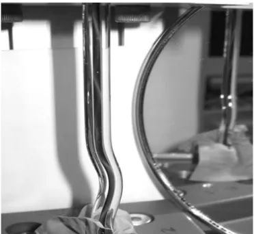
Others have shown that in straight horizontal wells, drill strings have 2 unique buckling modes, a 2D sine wave and a helix (9–11). The compressive force required for the string to transi-tion from a sine wave to helix is 41% more than the force necessary for it to initially buckle into a sine wave (9). The force required to reach the locking point in a straight well is always higher than the force required for helical buckling. This depends on the shape of the tube and specific properties of the filament as described above. In our hands, the lock point always occurred at a force much higher than the force required to achieve helical buckling (Fig. 2). Therefore, for simplification of the model, we assumed immediate transition to a helical buckling state, which was validated by comparing model and empirical data (Fig. 2). To validate this further, a white PTFE filament was inserted in a glass tube filled with blue dye. This filament was then com-pressed, and the filament was clearly observed to form a helix (Fig. 3) at less than half of the cutoff load (load cell capacity). However, even with the helix formed, the filament did not completely lock because of the low friction coefficient.
To validate the assumption that the transition lengths of the filament within the curved segments of the tube (i.e., the segments that did not contact the tube wall) were equal in the unbuckled and buckled states, SolidWorks CAD models were generated to compare the projected transition lengths. Pictures of the actual side-to-side path of a black filament (Dfilament⫽ 0.99 mm) through the glass tube (Dtube⫽ 1.5 mm) were used to recreate the geometry in equivalent CAD models (Fig. S3). In this case (where Dtube/Dfilament ⫽ 1.51), it was determined that the buckled transition length was⬇75% of the unbuckled transition length. In the limiting case when Dtube/ Dfilamentapproaches 1.0 (i.e., no space between the filament and the inner wall of the tube), these transition lengths become equal. For the case of the nylon (Dfilament⫽ 0.90 mm) and PTFE (Dfilament⫽ 0.97 mm) filaments tested in the steel tubes (Dtube⫽ 1.22 mm) by using the tension/compression system, the diameter ratios were 1.26 and 1.35, respectively. Given that these filaments occupied more space within the tube, the transition lengths between the unbuckled and buckled states were much closer than that for the black filament in the glass tube. Specifically, the buckled transition lengths were within⬇15% of the unbuckled transition lengths for nearly all systems tested, which translates to an error of⬍7% difference in contact lengths. In other words, the majority of the filament length is in contact within the tube wall for the curved segment (Lcurved⫺ Ltransition), and thus it was assumed that this would not significantly alter the predictive accuracy of the model.
Prototype Test with Muscle Tissue in Vitro
To study how the prototypes would lock and advance through muscle tissue, the tube/filament system was modified, and a sharp tip was added to the end of the steel tubes. Specifically, because all tests with the tension/compression system were performed against a noncompliant surface (i.e., a flat metal surface), the lock point would always be reached without any advancement of the filament. However, with a compliant sub-strate (e.g., tissue), it is essential that the tissue supplies sufficient opposing force to the filament to produce locking, otherwise the filament would advance alone through the tissue, thus preventing engagement of the clutch.
To ensure that locking would occur well before advancement of the filament alone through the tissue, the tissue yield stress of candidate tissues was analyzed. If the contact lengths for the filaments are known, with the tissue yield stress, one can calculate the minimum compressive force required to advance the filament alone through the tissue. To ensure engagement of the clutch, the compressive force required for locking must be less than the compressive force required for advancement of the filament through the tissue. To create a safety factor, we chose to design the lock point based on the yield stress for a less-dense tissue [liver tissue, which has a yield stress of 2.5⫻ 105Pa (12)]. The analytical model was used to refine the prototype tube properties (tube diameter, bend radius, number of curves, and lengths). For experiments with muscle tissue, we used a clinically available Arrow PTFE coated spring-wire guide (Dfilament⫽ 0.76 mm) with the central Nitinol wire removed (for increased flexibility). To increase the contact area between the filament and tissue, and to decrease the contact pressure required to achieve locking, a metal ball (D⫽ 0.79 mm) was affixed to the tip of the filament. The properties of the prototypes that were tested on muscle tissue are described inTable S4(rows 1 and 2). Use of the prototype required one hand to guide the tube (needle) while the other hand applied a force to the filament through a makeshift hand piece (Fig. 1E). Success of early prototype devices was defined by locking of the clutch and advancement of the complete unit. Based on this criterion, the initial success rate was 49% (28 of 57 tests). It was assumed that the significant failure rate was due to the compressive force being
Fig. 3. A helically buckled filament (white) is visible inside a glass tube filled with blue dye. Regions where the filament touches the wall can be distin-guished by its white appearance given a minimal amount of blue dye that exists between the filament and wall at points of contact.
Bassett et al. PNAS 兩 April 7, 2009 兩 vol. 106 兩 no. 14 兩 5543
ENGINEERING
APPLIED
BIOLOGICAL
applied to too small an area at the tip of the filament. Thus, the system was further refined by increasing the diameter of the tube (needle) to fit an increased metal ball diameter (D⫽ 1.59 mm) attached to the end of the filament. These changes increased the success rate to 75% (65 of 87 tests).
The other critical property of the prototype was disengage-ment of the clutch upon exit from the tissue. In theory, the clutch should disengage when the opposing tissue force against the filament decreases below the compressive locking force. Upon disengagement, the filament should advance alone while the needle automatically stops. Later tests were considered a success only when the needle stopped⬍3–4 mm after exiting the tissue and the filament disengaged and deployed (Fig. 4). Results were determined through visual observation and tactile response in the hand piece. Common failures included filament deployment before complete exit of the needle through the muscle tissue and delayed deployment of the filament after exit from the tissue. Of the prototypes that achieved sufficient locking, 31% (17 of 55) led to successful disengagement of the clutch. Twenty-three percent (7 of 31) of the failed attempts occurred because the filament deployed before complete exit of the tissue, whereas 77% (24 of 31) resulted from delayed deployment of the filament after exiting the tissue. We considered premature filament deployment to be a more favorable result than overadvancement of needle, which, in practice, could damage underlying organs. When filament deployment was delayed, it was generally due to a small piece of tissue that had become wedged between the needle tip and the filament, preventing disengagement of the clutch. It is noteworthy that the metal ball typically remained ⬇0.5–1.0 mm behind the point of the needle tip (inside the needle) until the needle exited from the muscle tissue. These failures were addressed by decreasing the inner diameter of the needle to reduce the gap between the metal ball and needle from 0.24 mm to 0.11 mm.
Altogether, the in vitro tests demonstrated a proof of concept for the engagement and disengagement of the clutch, whereas the analytical model was useful to iterate the prototype design to improve the locking mechanism for needle advancement through muscle tissue. Therefore, the prototypes with the best performances were selected for in vivo testing in a porcine model.
Prototype Testing with in Vivo Porcine Model
The performance of a proof-of-concept clutch-based needle device was evaluated in a deceased porcine model. Each needle was inserted transabdominally in unique locations and was recorded with a laparoscopic video camera. Three prototype devices based on the in vitro prototypes that had the lowest locking points (Table S4, rows 5–7) were tested: 2 3-bend S-tubes (the second having enhanced curvature to promote earlier locking) and a 4-bend S-tube. These prototypes used smaller diameter tubing (i.d.⫽ 1.70 mm), larger diameter ball (D ⫽ 1.59 mm), and a spring-wire guide filament (Table S5; see also
Fig. S4).
Laparoscopic videos showed that the prototype clutches en-gaged equally well for all 3 devices. This was due to the sufficiently low locking points and the handmade nature of the needle tips used, which were not as sharp as clinically available needles. This caused more force to be applied to the tip of the filament, promoting rapid engagement of the clutch. This also pushed the peritoneum away from the abdominal wall. Upon penetration of the peritoneum, a section of the needle tip appeared to have advanced into the cavity (average⬇2.2 cm, standard deviation⬇1.1 cm). However, close inspection of the videos showed that all filaments disengaged immediately upon penetration and that⬎60% of the overshoot can be attributed to the peritoneum being pushed into the abdominal cavity and not to the needle advancing through the peritoneum (Fig. 5 and
Movie S1 and Movie S2). The in vivo tests included a result where the needle was accidentally passed through the same hole in the peritoneum and another result where excessive force was applied to the needle, causing advancement after the filament disengaged, which was easily rectified by using less force.
The potential of the prototype clutch-based device to prevent injury was shown when a needle pressed the peritoneum in close proximity of the underlying viscera (⬇3–5 mm) but did not harm the viscera even after penetrating the peritoneum. This was achieved by the immediate disengagement and deployment of the filament, which prevented the needle from further advance-ment. We believe that these results demonstrate the potential to design an automatic mechanical clutch medical device to stop the advancement of a needle upon entry into a lower-resistance tissue compartment (e.g., abdominal cavity).
Conclusions
This work showed that an automatic mechanical clutch could be designed and manufactured from a rigid tube and flexible filament for medical use in accessing tissue or tissue compart-ments. The analytical model of the clutch mechanism was developed from theory previously described for oil well drill strings with empirical data from tension/compression tests. The developed model accurately predicted the performance of the clutch for all variables tested. Specifically, ⬎160 tests were
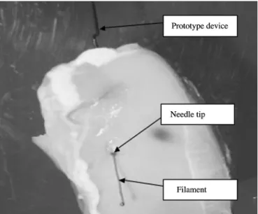
Fig. 4. Successful deployment of the filament in a muscle tissue model. The needle tip is observed at the interface of the muscle tissue, having stopped while the filament deployed as expected. The input portion of the prototype device is observed in the background.
Fig. 5. Image showing the automatic deployment of the clutch from inside an insufflated porcine abdomen. The needle stops and the filament deploys simultaneously. In this particular image, the clutch has prevented the needle from puncturing the underlying viscera.
performed on 17 different tubes and 2 filament types, and the results consistently fell within acceptable ranges of the model predictions. Using this refined analytical model, a functional prototype was developed and iterated, eventually achieving a 75% success rate for engagement of the clutch against muscle tissue in vitro. After demonstrating the potential disengagement of the clutch within the muscle tissue, proof-of-concept in vivo
experiments were performed. For 6 attempts in a laparoscopic pig abdomen model, the clutch engagement was 100%. Although we observed overshoot in each case as the peritoneum tented (because of our hand-sharpened needles), the needle came to a complete stop, and the compressive force transitioned to the filament, which disengaged in all experiments. It is important to consider that not all clinical applications involve a drastic change of resistance, as we observed with the laparoscopic model, and that this may vary substantially when advancing a needle. Although further refinement of the clutch is necessary to ensure that no false positive or overshoot events occur, the proof-of-concept devices showed great promise and may solve many of the challenges associated with accessing tissue compartments.
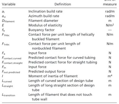
The mechanical clutch-based medical device does not require electronics or additional accessories and may provide a simple method for the safe placement of needles and deployment of catheters in a wide range of medical procedures. Using the analytical model, it may be tuned for specific tissue applications and tissue variation. It is expected to provide increased tactile feedback with an automatic stopping function with potential to reduce the risk of overshoot injuries. Further improvements to this system will focus on enhancing the cutting edges and geometry of the needle tip to prevent overshoot of the needle, in addition to testing within multiple tissues and animal models. For an explanation of nomenclature, see Table 1.
ACKNOWLEDGMENTS. We thank Terrance Norchi for providing advice
re-garding translational considerations, Demos Pafitis at Schlumberger for di-recting us to appropriate oil industry references, Dr. Denise Gee for technical laparoscopic assistance, and Dr. Douglas Shook for providing operating room access to observe catheterization procedures. This work was supported by the Deshpande Center for Technological Innovation at the Massachusetts Insti-tute of Technology and the Center for Integration of Medicine and Innovative Technology.
1. Aders A, Aders H (2005) Anaesthetic Adverse Incident Reports: An Australian Study of 1,231 Outcomes. Anaesth Intensive Care 33:336 –344.
2. Eltzschig HK, Lieberman ES, Camann WR (2003) Regional anesthesia and analgesia for labor and delivery. New Engl J Med 348:319 –332.
3. Harrison GR (1989) The epidural space. Anaesthesia 44:361–362 (lett).
4. Scha¨fer M, Lauper M, Kra¨henbu¨hl L (2001) Trocar and Veress needle injuries during laparoscopy. Surg Endosc 15:275–280.
5. www.fda.gov/cdrh/medicaldevicesafety/stamp/trocar.html, accessed February 28, 2009. 6. Frolich MA, Caton D (2001) Pioneers in epidural needle design. Anesthes Analges 93:215–220. 7. McCann RC, Suryanarayana PVR, Mobil E&P Technical Center (1994) Experimental
Study of Curvature and Frictional Effects on Buckling. OTC 7568:511–521.
8. Lubinski A, Althouse WS, Logan JL (1962) Helical buckling of tubing sealed in packers.
J Petrol Technol 14:655– 667.
9. He XJ, Kyllingstad A (1995) Helical buckling and lock-up conditions for coiled tubing in curved wells. Soc Petrol Eng Drill Complet 10:10 –15.
10. Dawson R, Pasley PR (1984) Drillpipe buckling in inclined holes. J Petrol Technol 36:1734 –1738.
11. Chen YC, Lin YH, Cheatham JB (1990) Tubing and casing buckling in horizontal wells.
J Petrol Technol 42:140 –191.
12. Figueredo SL, Brugge WR, Slocum AH (2007) Design of an endoscopic biopsy needle with flexural members. Am Soc Mech Eng J Med Devices 1:62– 69.
Table 1. Nomenclature used in this study
Variable Definition
Unit of measure
ai Inclination build rate rad/m
a Azimuth build rate rad/m
Dfilament Filament diameter m
E Modulus of elasticity N/m2
fb Buoyancy factor —
F1hbc Contact force per unit length of helically
buckled filament
N/m
F1nbc Contact force per unit length of
nonbuckled filament
N/m
Fa Input force N
Fcontact㛭curved Predicted contact force for curved tubing N Fcontact㛭straight Predicted contact force for straight tubing N
Fin Input force N
Fout㛭predicted Predicted output force N
I Moment of inertia of filament m4
Lcurved Length of curved section of design tube m
Lstraight Length of long straight section of design tube
m Ltransition Length of filament that does not touch
tube wall
m
Bassett et al. PNAS 兩 April 7, 2009 兩 vol. 106 兩 no. 14 兩 5545
ENGINEERING
APPLIED
BIOLOGICAL