Development of Conducting Polymer Based Biomimetic Muscles and
Fabrication Techniques for an Artificial Pectoral Fish Fin
by
S. Naomi Davidson
B.S. Mechanical Engineering (2002) University of California at Berkeley
Submitted to the Department of Mechanical Engineering in Partial Fulfillment of the Requirements for the Degree of
Master of Science in Mechanical Engineering at the
Massachusetts Institute of Technology May 2005
0 2005 Massachusetts Institute of Technology All rights reserved
MASSACHUSEMTS INS-TiTUE OF TECHNOLOGY
JLUN
6
2005
LIlBRARIES
Signature of Author mA-m 1 0 abngmerng TMufv 10 ')IVC Certified by_ Inn Hiintpr Profess<Development of Conducting Polymer Based Biomimetic Muscles and Fabrication Techniques for an Artificial Pectoral Fish Fin
by
S. Naomi Davidson
Submitted to the Department of Mechanical Engineering on May 19 2005 in Partial Fulfillment of the Requirements for the Degree of Master of Science in
Mechanical Engineering
Abstract
Fish possess a greater degree of agility, maneuverability, and energy efficiency over current underwater vehicles constructed by engineers. Kinematics studies show that a high degree of three-dimensional control of multiple active surfaces distributed around an undersea vehicle's center of mass is critical to achieve fish-like superior performance. However, current technology has yet to exploit the use of actively controlled surfaces for underwater locomotion. Major obstacles limiting effectively achieving designs capable of active deformations in multiple degrees of freedom lie in the complexity associated with traditional actuators and their associated manufacturing techniques. Conducting polymers possess numerous desirable physical and active properties which make it possible to grow rather than build artificial muscles for an articulated device. Their potential for co-fabrication make it possible to implement simpler more integrated designs as they have been shown to provide all the basic elements required for a Biomimetic robot including: force sensors (analogous to the Golgi organs in tendons), strain sensors (like muscle spindles), structural elements (such as bones, joints, and webbing), and actuators (akin to muscle). Rapid prototyping and molding techniques were used to begin the development of a co-fabrication process for a pectoral fin which will be made from and actuated by conducting polymers. Conducting polymer actuators provide the necessary structural flexibility while exceeding the 800 kN/m2 force
requirements typical of fish muscle by 40 fold. Maximum speed requirements of 2.1 Hz for swimming speeds up to 1.1 TLs' (total body length/s) are attainable at the strains required for metrics of the current artificial fin design.
Acknowledgments
There are so many people who have generously contributed their knowledge, expertise, inspiration, thoughts, encouragement, interest, and time during my endeavors as a master's student. In completing this thesis, I'm honored to take a moment to recognize and thank them for making this experience on the one hand possible and on the other as rich as it has been.
All the members of the polymer group and the BioInstrumentation lab share their time
teaching each other to use the numerous tools and machines in our lab. This culture of knowledge exchange has been as inspirational as it has been enabling. I am particularly grateful to Bryan Schmid, Angela Chen, Mike Del Zio, Rachel Pytel, Nate Vandesteeg, and Bryan Ruddy in this capacity. Patrick Anquetil not only offered his expertise, but was also extremely helpful and encouraging in offering advice on the direction of my research. He always made sure that I had every resource I could possibly use to make my work better or easier. Laura Proctor also played a vital role in this thesis. Not only did she help me edit it, but we also worked closely together forming the basis of the design for the mechanical model and taught each other the intricacies of casting and molding. Peter Madden and George Lauder, though not members of the lab, provided enormous inspiration. Peter's invaluable knowledge base of both the conducting polymers and the kinematics and physiology of the Bluegill Sunfish were a major driving force on this project. Of course, I'm especially thankful to Professor Ian Hunter for giving me the opportunity to work in a lab that is unparalleled in the opportunities it provides. Not only is the BioInstrumentation Lab a fun and educational place to be, it's also an unbelievable collection of resources that he has brought together and shares so generously with his students.
Alain, Christian, Dee, Whitney, Mike, and Lynne have been the best friends one could ask for. They kept me balanced, making sure I remembered to stop and smell the roses of Cambridge and Boston.
Though my family didn't teach me how to do engineering, they did teach me how to be the best engineer I can be. I can't begin to measure the contribution of my father, Howard; my mother, Susan; and my brother, Josh. Josh is one of the people I admire most in the world, his strength and courage are beyond imagining. I am immensely fortunate to have all of their support, wisdom, and love.
Contents
1.0 Introduction... 8
1.1 Conducting Polym er M aterials in a Biorobotic Fish ... 9
1.2 References... 12
2.0 Background Theory ... 15
2.1 Pectoral Fish Fin ... 15
2.2 M odeling and D escription of A ctuator Characteristics ... 18
2.3 D esign of an Artificial Fish Fin ... 23
2.4 Chapter References ... 24
3.0 A ctuator D evelopm ent ... 26
3.1 Effects of Deposition Electrode Materials on Polypyrrole Films... 32
3.1.1 Fabrication M ethods ... 32 3.1.2 Testing... 37 3.1.3 Results... 38 3.1.3.1 A ctive Properties... 38 3.1.3.2 Passive Properties... 50 3.1.3.3 D iscussion... 62
3.2 Em bedded W ire Inserts... 64
3.2.1 Fabrication M ethods ... 66
3.2.2 Testing... 69
3.2.3 Results... 70
3.3 Em bedded Electrodes in Flat Film s ... 77
3.3.1 Fabrication M ethods ... 77 3.3.2 Testing... 78 3.3.3 Results... 79 3.5 Chapter References ... 81 4.0 Co-fabrication ... 83 4.1 M olding Techniques ... 85
4.2 Integration of Conducting Polym er ... 90
4.2.1 Chem ical D eposition... 90
4.3 Chapter References ... 101
5.0 M echanical M odel of Artificial Pectoral Fish Fin ... 103
5.1 D esign Param eters ... 104
5.1.1 Pectoral Fin Anatom y ... 104
5.1.2 K inem atics of Pectoral Fin Sw im m ing ... 108
5.2 Compliant Mechanism Based Model of Pectoral Fin... 113
5.2.1 First G eneration M echanical M odel ... 114
5.2.2 Second G eneration M echanical M odel... 120
6.0 Conclusion ... 130
6.1 A ctuator Perform ance ... 130
6.2 Cofabrication... 131
6.3 M echanical M odel ... 132
1.0 Introduction
When we compare the current state of AUV (Autonomous Underwater Vehicle) technology with the stealth, efficiency, maneuverability and agility of fish we find the performance of man-made vehicles summarily lacking (Fish, 2003). In cases where an animal's functional performance far exceeds our own, careful observance and modeling of the driving forces for their superior capabilities can lead to significant gains. Analysis of the high performance maneuvers employed by fish versus those common to AUVs reveals fundamental limitations to the performance that can be expected from propeller designs (Fish, 2003; Kemp 2003). Paired pectoral fins are the primary thrust generators for low speed maneuvers in unsteady flow environments for many fish (Lauder, 2000). In kinematic analyses performed on pectoral fin swimming, data suggests that the source of the high performance of fish fins is due to active control of the fin's conformation. Engineers previously used rigid body dynamics to inform design parameters for underwater locomotion (Gibb, 1994). This assumption now appears to be insufficient as we discover more about controlled flexible foil swimming.
Investigation of the hydrodynamics and kinematics of fish fins during specialized maneuvering revealed four basic lessons indicating sources of their performance abilities. The first of these lessons involves the incorporation of multiple control surfaces (fins), which are widely distributed about the center of mass. A fish's fins vary in size and shape, and because of their positioning relative to the center of mass, allow refined control of large moments with relatively little force output. Second, these control surfaces must have a high degree of three-dimensional motion with flexible articulation relative to the body. The ability to rapidly reorient the fin surface allows the fish to generate and control a widely dynamic range of force vectors. This is the key to accomplishing the wide range of locomotor requirements for a single fin; for example, braking, turning, and hovering. Third, active conformational control of the fin surface enables fine tuning of body positioning for low-speed maneuvers. Again, small force outputs yield high performance results for precise movement control. Finally, fish simultaneously employ
these numerous control surfaces for maximum hydrodynamic efficiency. Analysis of wake interactions have shown that the dorsal fins are used in a variety of swimming routines to generate vorticity patterns which the caudal fin then capitalizes on for increased force generation, greater swimming efficiency, and improved maneuverability (Lauder 2003).
Achieving active control of in multiple degrees of freedom of flexible surfaces with motors and gears is extremely cumbersome. Traditional actuator technology is limited by rigidity, functionality, and physical footprint. Using motors, for example, to build an articulated fin accomplishing two of the four design goals outlined above becomes a significant challenge possibly even prohibitive. Artificial muscles, in particular conducting polymers as active smart materials, possess the characteristics necessary to create flexible yet active surfaces in almost any geometric construction (Bowers, 2004; Madden, et al., 2003). Integration of active materials into the structure of an underwater robotic device greatly simplifies the task of achieving active surface control. The potential for significant simplification exist not only in the manufacture and assembly of fins, but also in operational control of the mechanical device, and the effective achievement of the appropriate kinematics required for refined hydrodynamic control.
1.1 Conducting Polymer Materials in a Biorobotic Fish
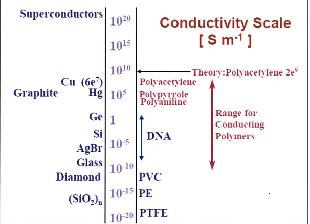
Conducting polymers are a unique class of organic materials that, depending on the conditions of their synthesis, exhibit electrical conductivities ranging on the order of a semiconductive material to a highly conductive material as shown in Figure 1-1 (Madden, 2000). One of the many compelling functional uses of these polymers is their ability to convert electrical energy into mechanical energy through an electrochemical doping process. Volumetric changes in a synthesized film lead to active strains as ions
to 2 % (Kaneto, 2004; Madden, Madden, and Hunter, 2002; Madden, 2003). This force capacity exceeds that of skeletal muscle by as much as 100 fold or greater.
Cu (6e
7)
Hg
Ge
Si
AgBr
Glass
Diamond
(SiO1)n
1020
101s
101010"
I
10-510-10
10-20Conductivity Scale
[ S
m
]
Theory:Polyacetylene 2e9 Polyacetylene Polvpyrrole Pofyamline Range for Conducting DNA PolymersPVC
PE
PTFE
Figure 1-1. A comparison of conductivities of common materials with conducting
polymers (PE is polyethylene, PVC is polyvinylchloride and PTFE is
polytetrafluoroethylene or Teflon©). (Source: Madden, 2000)
The active properties of these materials along with the inexpensive nature of their synthesis and manufacture places these materials in the operational range of many commercially used actuation technologies (Hunter, 1992, Bar-Cohen, 2001). In Table 1 a comparison of polypyrrole, a commonly used and well characterized conducting polymer, is made against many currently available and commercially successful actuators.
Superconductors
Table 1-1. Comparison between conducting polymers, natural muscle and other commercially available actuation technologies (Source: adapted from Kornbluh 2002).
Actuator Technology Maximum Strain Maximum Relative Speed
(%) Pressure (MPa)
Natural Muscle (Human 100 0.8 Slow
Skeletal)
Electromagnetic (Voice Coil) 50 0.1 Fast
Conducting Polymer 26 34 Slow
(Polypyrrole)
Shape Memory Alloy (TiNi) >5 >200 Slow
Piezoelectric (Ceramic -PZT) 0.2 110 Fast
Muscle is a distinctively advantageous actuation material because it has multiple integrated functions. Due to its material properties, it can be used effectively to provide breaking force, restoring energy as a spring, and structural integrity much like a strut. Work-loop experiments have shown, as expected, that muscles produce positive power as motors (Full, 2002). However, careful examination of the kinematics and kinetics of a variety of animals during locomotion also revealed muscular activity providing braking force for enhanced stability, tunable spring stiffness for energy efficiency and passive stability control, and structural integrity as struts. The multifunctional characteristic of muscle allows for greater integration, which in turn drives greater simplification in the architecture of specialized locomotory behavior. It has been shown in animals ranging from cockroaches to fish that capitalizing on the unique properties of muscle allows them to achieve highly specialized maneuverability in unpredictable terrains with relatively simple nervous systems, high energy efficiency, and robust operation even with broken or damaged appendages (Dickinson, 2000; Full, 2001).
Conducting polymers, such as polypyrrole, belong to a class of actuators known as artificial muscle because they also possess this multifunctional nature. This unique class of materials not only possess active properties like muscle they also exhibit a variety of
as well. It is therefore conceivable that an entire electromechanical device could be constructed from conducting polymers alone (Madden, 2003).
There are many potential benefits for utilizing materials possessing such versatile functionality. A potential benefit explored in the scope of this work is the construction of an active co-fabricated device. The co-fabrication of a biorobotic mechanism, or "growth" of an electromechanical machine as it is intended here, is attractive because it greatly enables the simplification of manufacturing processes while enhancing control over geometric and structural design constraints. In this thesis rapid prototyping and mold making techniques were used to build a working model of the pectoral fin for an artificial fish basing the design on parameters governed by the Bluegill Sunfish. The goal within the scope of this work was not to mimic the biological fin exactly as it is far too complex to effectively recreate (Dickinson, 2000; Full, 1999; Full, 2001). However, basic design parameters were extracted in a simplified functional model using kinematic and kinetic analysis from biological study. Means of integrating the conducting polymer actuators into the design were explored on the level of actuator development and co-fabrication techniques.
1.2 References
1. Ahn A. H., Full R. J. A Motor and a Brake: Two Leg Extensor Muscles Acting at
Same Joint Manage Energy Differently in a Running Insect. The Journal of Experimental Biology. 2002; 205:379-389.
2. Bandyopadhyay, P. R. Maneuvering Hydrodynamics of Fish and Small Underwater Vehicles. Integrative and Comparative Biology. 2002; 42:102-117.
3. Baughman, R. H. Conducting Polymer Artificial Muscles. Synthetic Metals. 1996; 78: 339-353.
4. Bar-Cohen, Y. Electroactive Polymer (EAP) Actuators as Artificial Muscles: Reality, Potential, and Challenges. SPIE-Intemational Society for Optical Engineering. 2001.
5. Bowers T. A. Modeling, Simulation, and Control of a Polypyrrole-Based Conducting Polymer Actuator, Masters Thesis. Cambridge, MA: Massachusetts Institute of Technology; 2004.
6. Dickinson, M., Farley, C., Full, R., Koehl M., Kram, R., Lehman, S. How Animals
Move: An Integrative View. Science. 2000; 288: 100-106.
7. Gibb, A. C., Jayne, B. C., Lauder, G. V. Kinematics of Pectoral Fin Locomotion in the
Bluegill Sunfish Lepomis Macrochirus. Journal of Experimental Biology. 1994;
189: 133-161.
8. Hunter, I., Lafontaine, S. A Comparison of Muscle with Artificial Actuators.
Technical Digest IEEE Solid State Sensors and Actuators Workshop IEEE. 1992; 178-175.
9. Kornbluh R., Pelrine R., Pei
Q.,
Stanford R., Oh S., and Eckerle J. Industrial and Commercial Applications Structures Technologies. 2002: Smart Structures and Materials Proc. SPIE, Vol. 4698.10. Fish, F. E., Lauder, G. V., Mittal, R., Techet, A. H., Triantafyllou, M. S. Conceptual
Design for the Construction of a Biorobotic AUV Based on Biological Hydrodynamics. Proceedings 13th International Symposium on Unmanned Untethered Submersible Technology. August 24-27 2003.
11. Full, R.J. and Koditschek, D. Templates and Anchors: Neuromechanical Hypotheses
of Legged Locomotion on Land. Journal of Experimental Biology, 1999, 202,
3325-3332.
12. Full, R.J. and Meijer, K. Metrics of Natural Muscle Function. In Y. Bar-Cohen (ed.) Electro Active Polymers (EAP) as Artificial Muscles, Reality Potential and
Challenges. SPIE and William Andrew/Noyes Publications. 2001: pp. 67-83.
13. Kemp, M., Hobson, B., Pell, C. Energetics of the Oscillating Fin Thruster.
Proceedings 1 3th International Symposium on Unmanned Untethered Submersible
Technology. 2003 August: 24-27.
14. Lauder G. V., Drucker, E. G. Morphology and Experimental Hydrodynamics of Fish Fin Control Surfaces. Proceedings 13th International Symposium on Unmanned
Untethered Submersible Technology. 2003 August: 24-27.
15. Lauder, G.V. Function of the Caudal Fin During Locomotion in Fishes: Kinematics,
Flow Visualization, and Evolutionary Patterns. American Zoologist. 2000; 40: 101-122.
Polymer Actuators and Devices (EAPAD), Yoseph Bar-Cohen, Ed., Proceedings of
SPIE. 2002; 4695: 176-190.
18. Madden J., Schmid B., Botha R., Hechinger M., Lafontaine S., Madden P., Hover F., McLetchie K., Hunter I. Polymer Actuated Variable Camber Foils. Proceedings 13th International Symposium on Unmanned Untethered Submersible Technology.
2003 August: 24-27.
19. Madden P., Madden J., Anquetil P., Yu H., Swager T., Hunter I Conducting
Polymers as Building Blocks for Biomimetic Systems. 2001 Bio-Robotics Symposium, The University of New Hampshire. 2001 August 27 -29.
20. Madden, P. G. Development and Modeling of Conducting Polymer Actuators and the Fabrication of a Conducting Polymer Based Feedback Loop, Ph. D. Thesis.
2.0 Background Theory
2.1 Pectoral Fish Fin
The relative performance of fish far exceed current underwater vehicle technology and is particularly impressive in the unsteady flow environments of wake zones. Fish are able to easily and stealthily negotiate high performance maneuvers such as turning on a dime, rapid reorientation and acceleration, and hovering regardless of rapid changes in the flow around them. Biologists and engineers are keenly interested in the source of this difference in performance (Bandyopadhyay, 2002; Lauder and Drucker 2004)
In a survey of the underwater kingdom there are many varieties of control surfaces that have evolved between different fishes (as well as on a given fish) in the form of multiple fins located about their center of mass. Using these control surfaces animals capitalize on three types of force generation: pressure drag, acceleration reaction, and lift. These forces are either actively or passively controlled through refined manipulation of flow over the surface of the fin (Fish, 2003). The complex interaction between multiple control surfaces on a fish's body has yet to be fully quantified. Until recently there was very little data illuminating the thrust partitioning between fins during swimming maneuvers as each fin was studied individually. Although in its infancy, the study of thrust partitioning for a Bluegill Sunfish has been performed at a speed of 1.1 TL s-1 (total body lengths per second). Figure 2-4 below summarizes the results of this study with a breakdown of the relative thrust contribution from each fin group during two basic swimming maneuvers; steady swimming and the initiation of a turn. At this speed the pectoral fins account for 50 % - 65 % of thrust generation (Lauder and Drucker, 2004).
A Soft dorsal: 9.1 ± 1,5mN (12.1%) Pectoral Caudal: 37 6(t 13.6 mN 28.5±t 1 9 mN (50 0%) (37.9%) B 501t dorsat: C -I11.2 * 2.0 mN Pectoral: 20.9 ± 6.5 mN (65 1%)
Figure 2-4. The components of wake force contributed by different fins of bluegill sunfish during a swimming were averaged over a stroke. The percent contribution of the force from each fin is reported in parentheses. The thrust generated from the soft dorsal, caudal, and pectoral fins during steady swimming maneuver at 1.1 TL-s-1 (A). A single pectoral fin produces a large amount of force in a turning maneuver. (Copied from: Lauder and Drucker 2004)
As we endeavor to match the agility and performance of nature's swimmers it is clear that there is much to be learned from using multiple control surfaces to achieve maneuverability and propulsion. Research shows that fish capitalize on these flexible foils for a variety of purposes (Kemp, 2003). By distributing multiple fins about their center of mass they are able to rapidly change the direction of the applied force on the flow over the body.
Studies have demonstrated that fish are able to actively control the conformation of the fin's surface and at lower speeds pectoral fins in particular are the primary source of thrust generation. This is enabled by a complex bone structure and multiple muscle and tendon attachments on each fin ray. Figure 2-5 shows a dissected image of the muscular and tendon attachments on the fin rays. Several layers of muscle are revealed (Figure 2-5 (B)). Each fin ray is controlled by a minimum of four muscles with its own tendon attachment at the base of the fin ray (Figure 2-5 (C)). This allows the fish to exert refined control over the direction and movement of each fin ray. The result of which is the cupping and curling the fin surface in the water for the active adjustment of stiffness,
surface area, and force generation. The control fish exert on the conformation of their fin translates to an ability to rapidly and efficiently exploit the hydrodynamics of their environment. Because classic approaches to underwater vehicle design have focused on rigid body dynamics, the focus of this project was to explore the effects of employing an actively controlled flexible foil.
Figure 2-5. A dissected image of the pectoral fin of a Bluegill Sunfish reveals the
complex muscular arrangement (A) at the base of the fin rays and the large connective tissue pad (CT) that attaches via tendons to the adductor superficialis (AS) muscles. As the upper layer of muscle tissue is cut (B) another set of muscles are revealed. The adductor superficialis has two distinct layers - superficial (AS1) and deep (AS2) is also composed of discrete bundles of fibers. Each fin ray is controlled by a minimum of four muscles each with a specific tendon attachment allowing the fish to exert refined control over the direction of movement of each fin ray (Copied from: Lauder and Drucker, 2004). The Bluegill Sunfish was chosen as a base model for informing the kinematics of swimming with active conformational control over the fin surface. It is a classic pectoral fin swimmer at swimming speeds below approximately 1.1 TL-s-1 (Gibb, 1994). Pectoral fin swimming is characterized by highly agile and finely controlled positioning in an unsteady flow environment. Fish are able to hover looking for food and rapidly react to
because it possesses a representative fin morphology, is locally prolific, and exhibits the desired swimming abilities.
2.2 Modeling and Description of Actuator Characteristics
While conducting polymers are a compelling technology there is still room for discovery and characterization in their development as an engineering material. This is the aim of the work covered in Chapter 3 of this thesis. Polypyrrole can generate active stresses as high as 40 MPa (two orders of magnitude greater than natural muscle) (Madden, 2002; Madden, 2001); exhibit maximum strains on the order of 10 to 26 % (Anquetil, 2004; Bay, 2003; Madden, 2002; Madden, 2002; Kaneto, 2004) although typical values for actuators are generally 1-2 % strain; and possess an elastic deformation range of up to 16 MPa (although at these stresses creep is an issue if forces are applied for more than a few minutes). Notable limitations in the use of these actuators is their relatively slow speed response, low electrical to mechanical efficiencies (~I %), and the requirement of an ion bath. In order to better understand these limitations and possible sources for enhanced performance, this section includes a discussion of the current understanding of the process by which electrical energy is converted to mechanical in these actuators and the model currently used to predict this behavior.
Polypyrrole is the conducting polymer actuator used for the focus of this thesis. It was chosen because it is one of the more robust of the electrochemically synthesized polymers, it is well studied, and models predicting its mechanical response have been developed. The source of conductivity in the polymer is a conjugated backbone of double bonds as shown in Figure 2-1. The conjugated molecular structure allows the delocalization of electrons along the backbone when a voltage is applied (Madden, 2000; Madden, et al., 2-001; Roth, 1995). This localized charge initiates the flow of ions into and out of the material as the charge is balanced. Conductivity is therefore sensitive to the structure of the polymer and the orientation of polymer chains within the material matrix. Synthesis conditions therefore greatly affect conductivity by impacting this mechanism for charge flow.
H
N
Polypyr-ole (PPy)
Figure 2-1. An illustration of the molecular structure shows the conjugated backbone of polypyrrole. (Source: Madden, 2002)
Electrochemical synthesis leads to the highest conductivity and the best mechanical properties recorded, for polypyrrole a typical conductivity is approximately 104 S-m
(Madden, 2000). The mechanism for expansion or contraction of the polymer is driven
by the migration of ions into or out of the material matrix. The result of this flow of ions
is a change in volume (V) and subsequent strain (c). Equation 2-1 describes the following linear relationship between strain and injected to injected charge (Q):
Q
C = a , 2-1
where charge density ratio (a) for polypyrrole is typically on the order of 10-10 C--m 3
The charge density ratio is governed by synthesis conditions as it is determined by the polymer structure discussed earlier (Madden, 2002; Madden, 2000; Madden, et al., 2003). Figure 2-2 shows a currently accepted circuit model of the impedance characteristics driving flow of charge for these electrochemical actuators. The impedance relationship between voltage source V, the double layer capacitance at the interface between the polymer and the electrolyte C, the electrical impedance due to the electrolyte and contact resistance R, and the diffusion impedance for mass transport into the polymer ZD are
C __
ZD
R
V
Figure 2-2. Circuit diagram describes actuator impedance for electrochemical actuators. (Source: Madden, et. al., 2002)
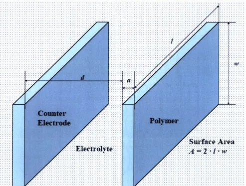
Geometry is a critical factor in modeling the behavior of electrochemical actuators. For the sake of simplicity, the parallel plate geometry shown in Figure 2-3 is assumed for all instances discussed here.
Figure 2-3. Parallel plate geometry used for modeling actuator behavior. Copied from: Madden, et al. 2002)
To begin, the diffusion impedance is given in the Laplace domain between the polymer and counter electrode at frequencies in the range of 100 pHz - 100 kHz:
ZD =1 2-2
a-C-s C,-Vol
where the a is the polymer thickness, 6 is the double layer thickness, C is the double layer capacitance, Cv is the double layer capacitance per unit volume, and Vol is the volume of the polymer. There are three time constants governing the speed of reaction/contraction: double layer charging time, volumetric charging through the polymer and mass transport of ions balancing charge in the film.
Since the charge in the double layer initiates flow of ions into the polymer, no charge transfer can take place until it has reached a sufficient level. The time constant for the double layer is:
d d
aC
RC =R -C - - , 2-3
ae' A Ce A
where A is the surface are of the polymer film, d is the separation between the film and the counter electrode, and Ue is the conductivity of the liquid electrolyte. Typical values
for conductivities of the electrolyte are 1 to 10 S m-1 while the double layer capacitance is commonly 0.1 to 0.4 F-m-2 (Madden, 2000; Madden, et. al., 2002). Given these typical values, for a response time of 1 ms, the separation between the polymer and the counter electrode should be from 10 to 100 mm or less.
Volumetric charging has a greater effect on reaction time as charge density must be transmitted through an internal resistance. Polypyrrole exhibits capacitor-like behavior for which the volumetric charging has two important situations governing the speed of actuation. In the first case, the electrolyte resistance is large relative to the polymer
where the reaction time is governed by the film thickness and the distance between the actuator and the counter electrode proportionally to the double layer charging time. In the second case, the polymer resistance is significant relative to the electrolyte resistance. Here the volumetric charging time constant is:
12
rRCVP = RP -Cv = -C, 2-5
where the volumetric charging time is increased by the square of the distance between electrode attachment points and is only mitigated by the factor of four when the actuator is connected at both ends.
Finally, the strongest factor dominating response time is the mass transport phenomenon.
2
rD a 2-6
4.D
The diffusion coefficient, D, in hexafluorophosphate-doped polypyrrole ranges between
0.7 to 7x 10⁻¹ m2-s-1 (Madden, 2000; Madden, et al., 2002) and the reduction in time by a
factor of four is only relevant if the film is exposed to ionic flow from both the front and back face.
One other factor governing reaction speed should be discussed. It would seem that since the capacitance is linear with voltage, doubling the maximum potential applied to the polymer would double the concentration and hence the charging rate. This is true to an extent but unfortunately, a limit exists on the maximum potential that can be applied to a film. Exceeding this limit causes film degradation and ultimately will result in destruction of the actuator. Because films have a limit on their actuation potential there is a corresponding limit to the current which can be driven through the film by raising the applied voltage. One method employed to mitigate this effect is to use a strategy of actuation known as resistance compensation. Essentially, an applied voltage, V, is determined assuming a maximum voltage, V7', at the double layer of the polymer which is to be reached but not exceeded including a compensation factor for the resistance drop, I-R, through the electrolyte.
Using this resistance compensation method increases the speed of actuation by maintaining the maximum potential gradient in the double layer (Madden, 2000; Madden, et al., 2002)
Given the above conditions, there are several considerations which may be addressed either in actuator development or implementation in a design:
" The distance between electrodes, d, and electrical attachment points, 1, should be
minimized,
" Film thickness should also be minimized within appropriate force constraints, " The degradation potential should be maximized.
Methods of increasing the performance of actuators based on the constraints discussed here are explored in further detail in Chapter three.
2.3 Design of an Artificial Fish Fin
While the inspiration to mimic the performance of fish in terms of their ability to maneuver efficiently, stealthily, and with tremendous agility is obviously enticing the process for doing so can be tricky. Replicating the complex physiology of the biological system is prohibitive, particularly with classic engineering technology. It is imperative in this sense to endeavor to identify systemic level simplifications in the design rather than trying to copy nature. This obviously entails achieving a detailed understanding of the physiology and kinematics of biological locomotor systems (Full, 2002). Through this understanding it is possible to overcome limitations in achieving equally performing mechanisms. Primary issues stem from the limitations on classic mechatronic technology, which is generally far too cumbersome and inefficient. Parts in the system are only able to perform singular functions forcing the incorporation of multiple devices
operated, and can provide a multitude of other functional abilities such as sensing (Lauder and Drucker, 2004; Madden, et. al., 2003; Madden, 2002; Madden, et al., 2001).
The speed and force capabilities of these actuators are within the measured outputs of the Bluegill Sunfish with maximum required frequencies of 1.2 to 2.1 Hz and forces of 100 to 200 mN. The peak power requirement measured for the Sunfish pectoral fin muscle was 27 W/kg. Polypyrrole outstrips this peak power requirement by as much as 44 %; typically delivering as much as 39 W/kg (Gibb, 1994). The possibility of matching the performance of fish-like swimming becomes a reality as conducting polymers can potentially reduce the complexity of the mechanical design while delivering the necessary actuation requirements for high maneuverability swimming.
2.4 Chapter References
1. Anquetil P. Large Contraction Conducting Polymer Actuators, Ph D. Thesis.
Cambridge, Ma: Massachusetts Institute of Technology: 2005.
2. Bay L., West K., Sommer-Larsen P., Skaarup S., Benslimane M. A Conducting Polymer Artificial Muscle with 12 % Linear Strain. Advanced Materials. 2003 Feb
17; v 15, n 4: p 310-313.
3. Bandyopadhyay, P. R. Maneuvering Hydrodynamics of Fish and Small Underwater
Vehicles. Integrative and Comparative Biology. 2002; 42:102-117.
4. Gibb, A. C., Jayne, B. C., Lauder, G. V. Kinematics of Pectoral Fin Locomotion in the Bluegill Sunfish Lepomis Macrochirus. Journal of Experimental Biology. 1994;
189: 133-161.
5. Full, R.J. and Meijer, K. Metrics of Natural Muscle Function. In Y. Bar-Cohen (ed.) Electro Active Polymers (EAP) as Artificial Muscles, Reality Potential and Challenges. SPIE and William Andrew/Noyes Publications. 2001: pp. 67-83.
6. Kemp, M., Hobson, B., Pell, C. Energetics of the Oscillating Fin Thruster.
Proceedings 13th International Symposium on Unmanned Untethered Submersible
Technology. 2003 August: 24-27.
7. Lauder G. V., Drucker E. G., Morphology and Exerimental Hydrodynamics of Fish
Fin Control Surfaces, IEEE Journal of Oceanic Engineering, v 29, n3, Jul 2004, pp.
8. Madden, J. D. Conducting Polymer Actuators, Ph. D. Thesis. Cambridge, MA:
Massachusetts Institute of Technology: 2000.
9. Madden, J. D., Madden, P. G., Hunter, I. Conducting Polymer Actuators as
Engineering Materials. Smart Structures and Materials 2002: Electroactive
Polymer Actuators and Devices (EAPAD), Yoseph Bar-Cohen, Ed., Proceedings of
SPIE. 2002; 4695: 176-190.
10. Madden J., Schmid B., Botha R., Hechinger M., Lafontaine S., Madden P., Hover F.,
McLetchie K., Hunter I. Polymer Actuated Variable Camber Foils. Proceedings 13th International Symposium on Unmanned Untethered Submersible Technology.
2003 August: 24-27.
11. Madden, P. G. Development and Modeling of Conducting Polymer Actuators and the
Fabrication of a Conducting Polymer Based Feedback Loop, Ph. D. Thesis. Cambridge, MA: Massachusetts Institute of Technology: 2003.
12. Madden P., Madden J., Anquetil P., Yu H., Swager T., Hunter I Conducting Polymers as Building Blocks for Biomimetic Systems. 2001 Bio-Robotics
Symposium, The University of New Hampshire. 2001 August 27 - 29.
13. Wilga C., Lauder G. Locomotion in Sturgeon: Function of the Pectoral Fins.
Journal of Experimental Biology. 1999; 202: 2413-2432.
14. Wilga C., Lauder G. Three-dimensional Kinematics and Wake Structure of the Pectoral Fins During Locomotion in Leopard Sharks Triakis semisfasciata. Journal of Experimental Biology. 2000; 203:2261-2278.
15. Wilga C., Lauder G. Functional Morphology of the Pectoral Fins in Bamboo Sharks, Chiloscyllium plagiosum: Benthic vs. Pelagic Staion Holding, Journal of
3.0 Actuator Development
Conducting polymers are attractive as a disruptive actuator technology over classical actuation systems because they are:
* lightweight ,
* have high power-to-mass density, * inexpensive to produce,
* silently operated,
* operated at low voltages,
* multifunctional such that single elements of a typical mechatronic device can be built without the incorporation of multiple parts,
* flexible (like muscle) which allows them to be wrapped around corners or incorporated into many different environments.
Current actuator technologies are limited in their ability to deliver all of these characteristics simultaneously. Table 3-1 summarizes many features of the conducting polymers as artificial muscles as they compare with mammalian skeletal muscle. As is evident in this list of properties, one of the major drawbacks to the polymers is the slow speed of actuation. Response times of skeletal muscle are over an order of magnitude faster than polypyrrole. Polymer contraction rates are their most rapid close to 3 %/s in contrast to the 100 %/s associated with muscle. Conducting polymers are also limited in strain output, where the average reliable strain is close to 2 % while muscle is typically capable of 20 to 40 % total relative contraction (Hunter, 1992; Madden, et al., 2002; Spinks, 2003). However, polypyrrole is over 100x stronger than muscle supporting maximum stresses as high as 40 MPa and at a significantly higher power-to-mass ratio. Coupled with the features listed above these actuators show commercial and industrial promise despite the limitations just mentioned. In order make these artificial muscles a truly versatile actuator technology; improvements in speed and/or strain are definitely required.
Table 3-1. The properties of polypyrrole as they compare to mammalian skeletal muscle show some of the strengths and limitations as an actuator technology (Source: Hunter,
1992; Anquetil, 2004).
Mammalian Skeletal Polypyrrole in 0.1 M Property
Muscle TEAP in PC
Displacement (Strain) 20 to 40 % 2 % (at 10 MPa)
Max Active Stress (Load) 0.35 MPa 40 MPa
Max Velocity (Strain Rate) 100 %/s 3 %/s (at 5 MPa)
Power to mass 50 to 100 W/kg 150 W/kg (at 5 MPa)
Efficiency 30 to 35 % 0.6 % (at 4 MPa)
3 % (at 30 MPa)
Stiffness (wet) 0.3 to 80 MPa (contracted) 0.8 GPa
Tensile Strength (wet) 0.3 MPa 20 to 85 MPa
Conductivity - 4.5x10⁴ S/M
Lifetime 101 105 (at 0.3 %)
In this chapter several fabrication methods were investigated with the hope of increasing the performance of polypyrrole. The driving force in conversion of electrical to mechanical energy in these actuators is the diffusion of ions into the material; this is also the major limiting factor in the speed of operation. Improving the strain rates involves manipulation of any one of the following factors (Madden, 2002):
" increasing the charging rate of the polymer such that ion flow into the material,
occurs at a faster rate without sacrificing the strain-to-charge ratio,
" increasing the strain-to-charge ratio without losing efficiency of the charging rate, " charging the double layer as quickly as possible.
film such that ions flow more freely through the membrane. However, this can lead to negative consequences. In the most efficient scenario only one ion, the relatively small anion, is the only mobile species balancing charge. Changes in the polymer that might enable or increase motion of the cation into the polymer during actuation would decrease the speed of reaction (Spinks, 2003; Madden, 2003). In the same vein, smaller dopant molecules with their increased mobility diffuse into the polymer more rapidly also increasing charging rate. However, this can decrease the strain-to-charge ratio as the film's volumetric expansion is dependent on the incorporation of ions into its matrix. The following discussion explores several different methods of increasing the performance of conducting polymer actuators.
Maximum Voltage Application
Another means of increasing the rate of reaction is to apply higher voltages. This increases the gradient at the double layer interface with the film which leads to an improved rate of charge flow (Otero, 1999, Madden, 2000; Madden, 2003; Spinks, 2003). For diffusion based reactions, the strain rates will depend on the difference between the polymer ion concentration and the double layer concentration as the ions move to balance charge between material and electrolyte. The greater the concentration gradient at this interface the faster the flow of ions will occur thereby increasing the strain rate (Madden,
2003). Increasing the applied voltage raises the concentration gradient. Unfortunately,
there is a limit on the maximum potential (degradation potential) which can be applied to the polymer. Exceeding this limit leads to degradation and even destruction of the actuator. Methods for pushing this ceiling involve changes in chemical structure of either the polymer or the electrolyte (Madden, 2003).
Electrolyte Resistance
Because of the resistance between the polymer and the electrolyte there can be a potential drop at the interface. A method of charging the double layer as quickly as possible by compensating for the interfacial resistance was developed by Madden et. al. and involves applying rapid pulses of voltages exceeding the degradation potential. This brief application of a high voltage across the film brings it to the desired voltage as rapidly as
possible without degradation affects (Madden, 2000). This strategy, known as resistance compensation, involves applying a shaped potential which initiates a large potential pulse that diminishes as the ohmic drop decreases. The resistance between the polymer and the electrolyte is estimated from measurements of the current draw upon application of the initial voltage pulse. The potential is adjusted as the difference between the applied potential and the estimated solution potential drop is less than or equal to the desired potential across the polymer (Madden, et al., 2000). In active tests performed in this chapter this resistance compensation technique was used.
Actuator Resistance
Another method of increasing the performance of these actuators is to decrease the resistance generated in the course of achieving electrical connection with the polymer. As the resistance compensation method seeks to mitigate this effect by applying an adjusted voltage, decreasing the effect at the design level is also important. Achieving minimum cell resistance can be accomplished by reducing the resistance of the polymer itself or by incorporating conductive materials into the matrix of the polymer. Several different strategies involving embedding gold which is highly conductive (a = 4.5 x 10⁷
S-m-) with polypyrrole (o = 104 S-m%). The aim of incorporating the conductive material
was to diminish either the cell resistance at the working electrode or along the length of the polymer. While the incorporation of materials into the polymer can decrease the contact resistance, or the overall resistance of the polymer, they can also lead to earlier mechanical failure and increased mechanical impedance within the actuator. As fabrication methods following this model were explored, these potentially negative effects were also examined.
Actuator Length
film creates greater resistance to current flow. The relationship between voltage drop, V, along the length, x, of a polymer film is given by:
V = dx, 3-1
( A -x.-)
where I is the current density, a is the conductivity, and A is the cross-sectional area of the film (Madden, 2003). The voltage drop has a negative effect on the speed of actuation because it lowers the potential at the double layer thereby decreasing the rate of flow of ions into the polymer. For many actuator applications then, these two parameters seem to be at odds. Long actuators are needed for increased strain, and thin actuators increase speed but also reduce the efficiency of the flow of ions. In a study conducted by Peter Madden two films were synthesized; both of which were 120 mm in length but had different cross-sectional areas. The thin film had a relatively low conductivity of 496 S-m-1 and a cross-sectional surface area of 6.4x10⁻⁸ m2 while the thick film was 6920 S-m~
1 with a cross-sectional surface area of 3.Ox 10-7 M2
. In measurements of the potential
along the length of these two films, under the application of an equivalent signal, Madden measured a total drop of approximately 70 % in the case of the high resistance strip versus a 30 % drop in voltage over the length of the low resistance strip. There are two ways to mitigate the negative effects of increasing the resistance of the polymer actuator when long or thin films are required. The first is to decrease the distance between the electrical connections and the second is to reduce the resistance of the polymer.
Strain to Charge Ratio
Increasing the strain-to-charge ratio is another means of enhancing the strain rates of these actuators. In one study it was reported that increasing the size of the mobile ion into the polymer had such an effect (Kaneto, 2004). Another effect that can occur within the electrolyte bath during actuation is the incorporation of solvent molecules as ions flow through the polymer. In this way, the added volume of the solvent leads to a greater strain-to-charge ratio (Madden, 2002; Otero, 1998). Although much work can be done with the choice of solvent in terms of developing the speed and strain rates of conducting polymer actuators, this was not explored within this thesis.
Another material property which should be mentioned is the elastic modulus of the synthesized films. Decreasing the stiffness of the film will allow larger displacements for a given load. Increasing the modulus, E, has the effect of increasing the stress,u, that that can be applied to the actuator:
o- = Ec + aEp. 3-2
where E is the strain, a is the strain/charge ratio, and p is the charge density. A greater Young's modulus is therefore a desirable effect as it increases the stress that can be generated per unit charge (Madden, 2003).
Actuator Testing
Several methods for increasing the performance of polypyrrole actuators were explored in this chapter. Some techniques involved the incorporation of materials into the matrix of the actuator either for the purpose of increasing the overall conductivity, decreasing the distance between electrodes, or reducing the resistance at the electrical connection sights. Changes in the material properties of the films were also explored at the synthesis level. The fabrication methods are detailed and the results of these growth techniques were quantified through measurements of their active properties. Active testing was performed on the actuators in a dynamic mechanical analysis (DMA) device that was designed and built to measure conducting polymer films under isotonic actuation conditions (Madden, and Rinderknecht, 2002; Rinderknecht, 2002). The specifications for the DMA are:
* 1 mN minimum resolvable force (25 kPa minimum stress for typical films), * 1 mm minimum displacement (0.017 % minimum strain for typical films), * 100 Hz closed-loop bandwidth in isotonic mode,
* 1 N maximum force (25 MPa maximum stress for typical films), * 3 mm maximum displacement (50% maximum strain for typical films).
3.1 Effects of Deposition Electrode Materials on Polypyrrole Films
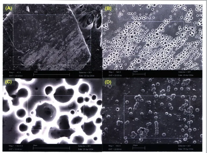
In this section the effects generated by changing the material at the deposition electrode during synthesis were studied. The material properties of the films fabricated underwent notable changes in conductivity, porosity and texture, mechanical strength, and maximum degradation potential. As discussed previously these all have significant influence on the strain rates and stresses achievable by the actuator. In some cases, the increase in strain amplitude was as high as 93%. Polypyrrole films were synthesized on the following electrode materials: glassy carbon, gold, nickel, platinum, and stainless steel. The resulting actuators were then characterized for mechanical and electrical properties.
3.1.1 Fabrication Methods
Films were grown in a solution of 0.05 M distilled pyrrole monomer and 0.05 M tetraethylammonium hexafluorophosphate in propylene carbonate with 1% distilled water. The film was synthesized galvanostatically at -20 'C at current densities of 1.25
A-m-2
Deposition chambers were constructed for performing film synthesis of several materials simultaneously. Depositions of flat films were made on gold, nickel, and platinum thin metal foils except for the glassy carbon films which were grown on a small section of a plate. Table 3-2 summarizes the material specifications of the metals used for flat films.
Table 3-2. The list of specifications for the metals used for flat films; selection was
based on purity.
Sample Gold Nickel Platinum
Thickness (mm) 0.0254 0.0254 0.0254
Purity (%) 99.95 99.99 99.9
A square chamber was constructed in Delrin @ to hold four sample materials at a time
and act as a vessel for the deposition solution. Figure 3-1 shows the configuration of the plates that provided evenly spaced windows between the deposition materials and electrodes. These window plates were used to position the foils as well as to provide a compressive electrical contact with the working electrode. A sheet of stainless steel was used as the counter electrode and mounted using Kapton © tape on the surface 28 mm from the working electrode materials. The samples were all cut and taped into the windows such that a 25 mm2 surface area was exposed. There is a separate window covering for the glassy carbon plate because of its greater thickness.
28mm
Working electrode materials were polished with 1500 grit (60 particles/mm) sandpaper in between depositions in order to remove any small particles of polypyrrole. They were then cleaned with acetone. Table 3-3 provides a list of dimensions of the samples that were used for the active property testing performed in this chapter. Films were taken
from two separate deposition batches. Each batch is denoted by the sample name.
Table 3-3. The following is a summary of the flat film dimensions for the samples that were used for testing. Films were taken from two separate each of which is denoted by name.
Material Sample Film Film Width Film
MtranaeLength name (m)Thickness
(mm) ( (mm) (pm) Gold AuN3 10 5 50 Glassy GCM10 10 7 40 Carbon GCN3 10.25 5 52 Platinum PtN3 8.75 5 65 Nickel NiN3 10 7 40
The deposition electrode materials used differed slightly for the tubular films. Glassy carbon, nickel, and platinum were still used but the gold material was substituted for stainless steel. Films deposited on gold have a tendency to be difficult to remove from the deposition electrode as the polymer seems to almost bond with the metal, while the opposite is true for stainless steel. Because stainless steel does not bond as well to the polymer during synthesis it was a better choice for this process. Removal of films without damaging them was an issue when synthesizing tubular films unlike during the fabrication of the flat films. This is because peeling the polymer from a flat foil.introduces far less friction than inching a tube off of a 200 mm long, 1 mm diameter rod. Table 3-4 lists the purity and dimensions of the materials that were used for tubular
Table 3-4. A list of materials and properties used for tubular film synthesis; selection
was based on purity.
Sample Nickel Platinum Stainless Steel
Diameter (mm) 1 1 1
Purity (%) 99.98 99.95 Fe:Cr:Ni;70:19:11
The deposition chamber for tubular films was simply a 500 mL graduated cylinder with a columnal insert which held samples upright in the container in the configuration shown in Figure 3-2. Samples were generally grown three at a time (Figure 3-2 (a and b)) with a stainless steel counter electrode which hugged the walls of the cylinder. Depositions were formed on the metal rod core and then slid or inched off once synthesis was completed (Figure 3-2 (c)). Because of the length of the column, and the different material properties of the metals, the deposition electrode rods would sometimes have a tendency to bow creating an uneven electric field between the working electrode and counter electrode in the rim of the cylinder. There were no visible differences generated from this error, but it should be mentioned that the spatial control in this set up was not as effective as it was for the flat films.
+- 25 A rnm
(a) (b) (C)
Figure 3-2. The deposition chamber used for tubular film synthesis; three samples were loaded at a time (a) with a steel counter electrode that fit snugly against the perimeter of the column, the rods were packed at evenly spaced intervals in the center of the cylinder
(b), once deposition was complete the core material was removed (c).
Table 3-5 provides a list of the materials that were used for testing. Samples were taken from three different depositions. As with the flat films, the working electrode materials were polished with 1500 grit sandpaper in between syntheses. They were then wiped clean with acetone.
Table 3-5. The materials used for testing of tubular films were taken from deposition batches. Each batch is denoted by the sample name.
three separate
Sample Film Film Cross- Film
Material name Length sectional area Thickness
(mm) (10-6 m2 ) (m) Glassy GCM18 8.1 0.157 55 carbon PtM31 11.55 0.126 40 Platinum Ptl 14.1 0.142 45 NiM31 11 0.113 36 Nickel Nil 9.5 0.026 8.3 Stainless SSM31 8.5 0.141 45 steel SS1 9.95 0.173 55 3.1.2 Testing
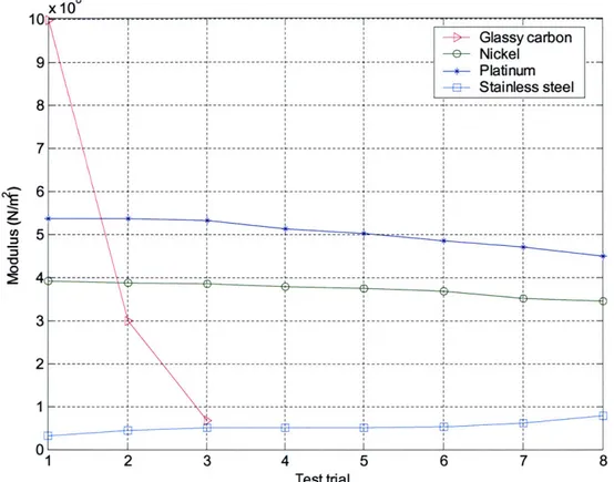
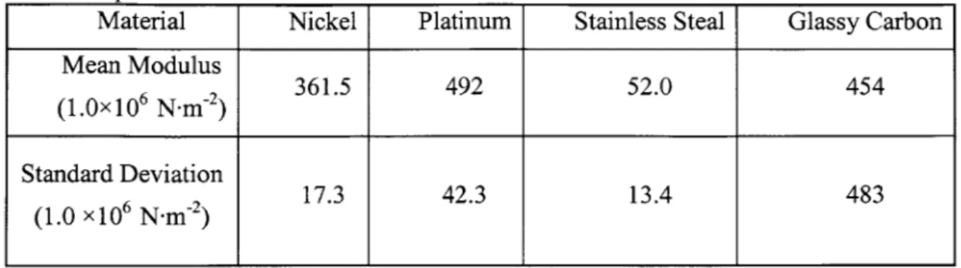
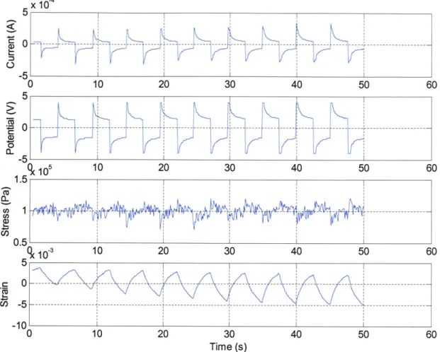
Films were tested for differences in their active and passive properties. The dynamic tests were performed on the DMA using the resistance compensation waveform developed by Madden et al., where a 4 V amplitude signal was pulsed through the film for 1 ms. Active strains, charge injection, and maximum voltages were measured for the samples at various frequencies and stresses. Figure 3-3 shows the results of a typical test. Strain and charge amplitudes reported were averaged over the 10 cycles of each isotonic test. The following passive properties were measured directly: 1) Conductivity, 2) Density, and 3) Young's modulus. A scanning electron microscope was used to view surface characteristics under magnification. Features of interest generally included porosity and surface roughness or texture.
X10 5 2 0 -- -- - -- - - -- ---- --- -- -- -- -- -- --- --- --- --- --- --- ------- --- -5 0 10 20 30 40 50 60 5 0 - - -- - - - -- - --- --- --- --- - - T--- --- --- -- --- --- --- -- -- ---- --5 0 106 10 20 30 40 50 60 1.1 CL CO) 0.9 0 10 20 30 40 50 60 0.015i I I C (I, 0.0 1 ---- - -- --- -- - - --- -- - - -- --- ---0 10 20 30 Time (s) 40 50 60 Figure 3-3.
Typical test results shown for a sample synthesized on
nickel driven with a
Figure 3-3. Typical test results shown for a sample synthesized on nickel driven with a
+0.8 V versus Ag/AgClO 4 at 0.25 Hz signal isotonically at 1 MPa for 10 cycles.
3.1.3 Results
3.1.3.1 Active Properties
The results of active testing of the flat films grown on gold, glassy carbon, nickel, and platinum were difficult to assess at the lower excitation voltages. In Figure 3-4 the four actuators' average strain results are shown under an applied potential of ±0.8 V versus
Ag/AgClO4 and a frequency of 0.25 Hz. The only consistent correlation between deposition material and performance is the lower strains exhibited by the actuator grown on a nickel working electrode. This trend continues in Figure 3-5 while another seems to become apparent; the actuators begin to differentiate in their performance characteristics
at the increased voltage applied of ±1.2 V versus Ag/AgClO 4. The actuators synthesized on platinum foil generated consistently higher strains at each isotonic test. The
performance of platinum films is followed by gold and nickel in that order. The film grown on the platinum foil showed an average increase in performance of 0.17 % strain or a 15 % increase overall over the next best actuator. The results for glassy carbon are not shown in Figure 3-5 as the sample failed in the first trial of the +1.2 V testing cycle. The four samples used for the tests shown in Figure 3-4 and Figure 3-5 were: 1) AuN3, 2)
GCN3, 3) NiN3, and 4) PtN3 OR 1.6 1.5 1.4 1.3 1.2 1.1 U.1 0.2 0.3 0.4 0.5 0.6 0.7 0.8 0.9 1 1.1 Stress (10 Pa)
Figure 3-4. Strain versus stress characteristics for flat films tested isotonically at an excitation voltage of ±0.8 V versus Ag/AgClO 4 and a frequency of 0.25 Hz show erratic responses between samples at different stresses.
- -- - - --- -- -- -- --- - --- --- --- - --- --- -- --- --- --- - --- --- --- --- -- -- - -ElGold --- Glassy carbon * Nickel --- --- e Platinum - ---- --- - - - -- - --- ---T
--1.5 1.4 1.3 - 1.2 C/ 1.1 1 0.9 fl8 0 0.2 0.4 0.6 0.8 1 1.2 1.4 Stress (10 Pa)
Figure 3-5. Strain versus stress characteristics for flat films tested isotonically at an excitation voltage of ±1.2 V versus Ag/AgClO4 and a frequency of 0.25 Hz consistently
show the platinum film as producing the highest strains.
Although a consistent trend is more evident in the films grown with a tubular geometry, it is not exactly the same trend seen with the flat films. The following four samples used for the tests shown in the next three figures (Figure 3-6, Figure 3-7, and Figure 3-8): 1)
GCM18, 2) NiM31, 3) PtM3 1, and 4) SSM3 1. Almost immediately evident in Figure 3-6
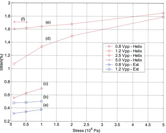
for films being tested with ± 0.8 V versus Ag/AgClO 4 and a frequency of 0.25 is the equal, if not greater, strains demonstrated by the films grown on the nickel deposition electrode over all the others in the group. While the increased performance is not striking amongst the top three films (nickel, platinum, and stainless steel) it is a far more uniform result than that seen in Figure 3-4 with flat films at the same excitation potential.
-- - - - --- - --- -- --- -- --- -- - - --- --- -- ------- --- --- - ----- --- -- - -- - -- ---- -- - - - - ---- --- --- -- - - --- Gold *- Nickel -e- Platinum --- --- ----- -- -- --- --- ---- -- ---- ---
1 0.9 - - -- ---- ---0 .8 -- -- ---- -I - --- --- --- --- --- - --- ------- ---E- Glassy carbon 0.7 -*- Nickel 0 .7 ---- --- --- - -- --- --- -- - -*N-k--- Platinum -+- Stainless steel ----.--- --- --- --- - --- -- --- --- --- --0.6 ---- -- - - ---0.2 --- --- - --- --- - --- --- --- --0 0 0.2 0.4 0.6 0.8 1 1.2 1.4 Stress (10 Pa)
Figure 3-6. Strain versus stress characteristics for tubular films tested isotonically at an excitation voltage of ±0.8 V versus Ag/AgClO 4 and a frequency of 0.25 Hz exhibit large strains for the nickel, platinum, and stainless steel actuators.
In the results shown for an excitation voltage of ±1.2 V versus Ag/AgClO 4 and a frequency of 0.25 Hz, the increase in differentiation between the nickel deposited film continues. The actuator shown an increase in strain amplitudes produced by as much as 53% over the next best films. The stainless steel and platinum films continue to produce similar results in this set of tests. One more increase in actuation properties is exhibited in Figure 3-8. While the nickel film continued to show a 67% increase in strain output over the next best group of actuators it also demonstrated higher load capacity. This increase in load bearing capacity was also seen in the actuator synthesized on platinum.