~tp/
JUL 30 1924 R AR COMPARATIVE COSTS OF HTDRO-ELECTRIG PLANTS NO. 3 & 4
of the
NTEW ENGLAND POWER C0MPANY OF THE DEERFIEID RIVER AT SHELBURNE FALLS, MASSACHUSETTS
Massachusetts Institute of Technology Cambridge, Massachusetts
Harry Goodman Nathan Ginsburg
Professor A. L. Merrill,
Secretary of the Faculty,
Massachusetts Institute of Technology, Cambridge, Mass.
Dear
Sir-This thesis was undertaken with the purpose of fulfilling, in part, the requirements of the Massachusetts
Institute of Technology for the degree of Bachelor of Science in Civil Engineering.
The authors wish to exoress their
indebt-edness for the assistance and guidance given by Professor H. Ke Bar-rows.
The authors wish, also, to thank the employees of the New England Power Company at Shelburne Falls for the aid given them on their visit to the plants.
Respectfully yours,
Course I3
G/L EJCourse
TABLE OF 0 ON TEB7NTS Page INTRODUCTION OB T T . * METHOD . REPORT .
DESCRIPTION OF PLANT NO. 3 Location
Dam .
Powerhouse
Penstocks - - -
-Electrical Equipment DESCRIPTION OF PLANT NO. 4
Location - -Tunnel - * * Powerhouse - . -Penstocks - - -7Electrical Equipment SUMMARY . . . Plant No. 3 * a * a * a * a * a * a * a * a Plant No.4 -
-Detailed Cost of Plant No. 3 Detailed Cost of Plant No. 4
APPEIWIOES a a a a a a a a a a a a. a . a .~ . - 0 . . - -* * - 0 - -9 . . . . a . . . . . . .. . . . a . . a . 9 - - - * 10 - . . - - - 11 * - -a - - - - * 12 . . - - - . 13 14002
Quantities in Dam - - 0 - - - - . * * *
Concrete . - - - . e 13
Spillway . . * - - - 13
Submerged & Surface Sluice & Conduit Intake . . 17
Rock Excavation . . . 19
Spillway . . . . .. . . . . -. 19
Submerged & Surface Sluice & Condtdt Intake . . 23
Before Intake to Conduit . . . 23
Quantities in Conduit . . . 26 Concrete Rock Excavation out Fill Quantities in Canal Fill . . Right Bank Left-hand Side Excavation Rip Rap Quantities in Penstock Concrete .* 0 . 0 0 . . 0 0 . 26 . 0 0 00.0 0 0 26 . . 0 . . 0 . .0 0.0 0 - 27 - - - - 0. 0 0 - 28 . . . 0 - - - 0 0 0 28 . 0 0 0 0 0 0 0 28 0 - 0 0 - - 0 0 - - 30 * - - * * - * 0 - - 0 32 - 0 - - - 0 0 * 0 0 33 . . . 0 0 0 34 .0 0 0 0 0 0 34 Steel Excavation . . 0 0 .0 . . . .0 0 . . . . ~ 35 . . . . 0 36
Fill Above Original Ground Level
* 13
- - 0 0 37
TABLE OF 0NTENTS (Continued) Quantities in Powerhouse Concrete . . . . . . . . . .0 Substructure . . . .
Below Springing Line of
Above Springing Line of Superstructure
Rip Rap
APPENDIX B- Plant No. 4
Quantities in Dam Spillwqy . . Concrete Rock Excavation Earth Excavation Earth Embankmant Retaining Wall Concrete -0 . . - 0 Pa.e . S S 5 38 . . . 38 . . . 0 38 Arch. . - .. 38 Arch . . . 40 . . . 42 - . . . . - . 42 - 0 0- 0 0 -* - - 43 . . . 0 0 43 . . . 43 . 0 0 * . 0 0 . . 43 . . 0 0 0 0 0 0 0 44 . . . - - - 45 - 0 - - 0 0 - - - 46 0 0 0 0 . 5 0 0 0 0 0 0 0 0 0 0 Rock Excavation Earth Excavation Sluice 0 0 . .0 . . .0 . . . .6 Concrete e Earth Rock
-Excavatign Around Dam
Rock Excavation Earth Excavatioi * 0 . . . . . . . . . . 0 . . . e . - 0 0 - - - -0 - 0 0 0 0 0 0 0 0 0 0 0 0 0 . . 0 . . . 0 0 . 0 . . , . . 0 . . . . 50 . 50 . 51 56 58 0 0 . . .
Tunnel Intake Concrete Tunnel Outlet Earth Excal Concrete Tunnel Rock Excav, Concrete Earth Exca Brick Timber Totals Reinforced 0. . . vation . . - -. . 0 . . 0 . 0 0 - 0 0 0 59 . 0 0 0 . . . . 0 . .0 0 . 59 . 0 . . . . . . . . . . . - 60 . . . 61 ation . . . 0 . . - - - e 61 . . . , . 0 0 0 0 0 0 . . 0 61 vation . . . 61 . . . 61 . . . 0 . . . 0 . 0 . . . . 0 . 61 . . . 0 . . . 62 Steel . . . .. . . . . 63 Penstocks Forebay .. Substructure . Concrete . Rip Rap . .0 000 0
APPENDIX 0 - Hydrology - Plant No. 4 Method used in Obtaining Killows
. .0 . 0 0 . 0 0 0 0 0 0 0 0 0 0 o . . . 0 . 0 . . . 66 . 0 . . . 67 0 . . . 0 0 0 0 0 68 att-Hour . Output- 0 . . , . 68 Flow, 1915z1920 0 . . . .
Flow Duration Table . . 0 . . . .
. . . . .
. . . . 0
mean . 0 0 0 0 0 . . . . 0 0 0 74
Wet Year . . . . . . . . - - 0 74
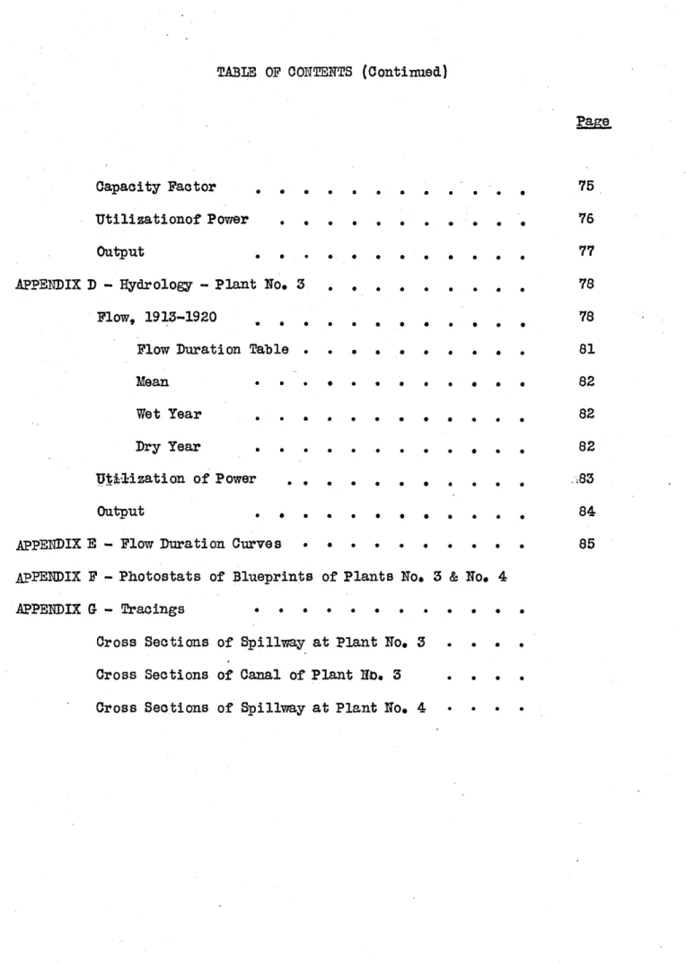
TABLE OF ONTENTS (Continued)
Page
Capacity Factor
Utilizationof Power . .
Output . . .
APPENDIX D -Hydrology - Plant No. 3 .
Flow, 1913-1920 . . .
Flow Duration Table .
Mean . . .
Wet Year .
Dry Year . . .
Utid1ization of Power . .
Output . . . .
APPENDIX E - Flow Duration Curves .
S 0 0 * 0 0 0 * 0 0 0 * 0 0 0 . . 0 .0 . 0 0 .0 . . . .0 . . 0 .0 . . 0 .0 . . . .0 . . . .0 . 0 0 .0 * 0 0 0 * 0 0 0 . , 0 0 77 . . . . 78 78 . 0 0 . 81 . 0 0 0 82 . 0 . 0 82 . . . 0 82 . . 0 0 83 . . 0 . . 0 . 0
APPE1DIX F - Photostats of Blueprints of Plants No. 3 & No. 4
APPENDIX G - Tracings 0 . . . .
Cross Sections of Spillway at Plant No. 3 . . . . Cross Sections of Canal of Plant No. 3 . . . *
INTRODUCTION
OBJECT:- The object of this thesis is to compare costs of the hydroelectric plants No. 3 and No. 4 of the New England Power Company, located on the Deerfield
River near Shelburne Falls, in order to ascertain the annual cost per kilowatt hour output at the switchboard.
METHOD:- The method of procedure was to determine the quantities of mater-ials used in constructing the plant from blueprints (photostat copies of which are included in Appendix & . The cost figures applied to these quantities were secured from Professor Barrows. The cost of the hydraulic and electrical
equip-ment was obtained by applying a cost of five dollars per horse power for the hy-draulic equipment and eighteen dollars fifty cents per kilowatt forrthe electrical equipment while the cost of the superstructure was found by applying a cost of fifteen cents per cubic foot (inside dimensions).
The annual charges were figured at the switchboard for each plant by applying definite percentages of the total cost.
The output in kilowatt hours for each plant was figured as ex-plained in Appendix
6).
DESCRIPTION OF PIMTT NO. 3
This station is located in the village of Shelburne Falls,
LOCATION on the Deerfield River, about three miles above Station No. 2.
The dam is concrete, of ogee spillway section, built on
rock throughout, fifteen feet in maximum height and four hundred seven-ty-five feet long. One submerged and one surface sluice are provided on the west end of the dam. These are controlled by double-stem timber
gates, operated by a single motor-driven hoist of fifty thousand poundst DAM
capacity. The dam diverts water into a reinforced concrete conduit twelve feet six inches high, seventeen feet wide, and six hundred seventy-seven feet long, running underneath buildings of the Lamson & Goodnow Manufacturing Company. The conduit intake is controlled by
four double-stem timber gates operated by four motor-driven hoists of fifty thousand pounds' capacity and the conduit discharges into a canal
thirty-six feet wide at the bottom, twenty-three feet maximum depth and six hundred sixty-five feet long. The head at this plant varies from sixty to seventy feet and is normally sixty-four feet,
The powerhoutse is located on the -west bank of the river below the end of the canal, with one-half the building two stories and the other half one story in height. The building is
dimensions are 31' x 971 and 531 high in the two-story sec-tion.
On the lower end of the canal, three steel
ptm-stocks ten feet in diameter and one hundred fifty-nine feet long connect the waterwheel casings which are thirteen feet in diameter and are located outside the powerhouse. Each
pdnstock is controlled by two double stem timber headgates, PE9STOCKS one operated by a hoist of fifty thousand pounds' capacity,
and the other by one of ten thousand pounds' capacity. Three 3,200 H. P., W. S. Morgan, horizontal, forty-four-inch, double
runners, two hundred fifty-seven revolutions per minute, cen-tral-discharge turbines are installed at the station. Each unit is controlled by a Lombard Special, horizontal,
direct-connected governor of seventeen thousand foot pounds' capacity The complete electrical equipment was supplied
by the General Electric Company and consists of: ELECTRICAL EQZUIPMNIT 3 2000 K. V. A., 2300 V., 3.phase, 60 cycles, 257 r. p. m.
horizontal, waterwheel-driven generators.
2 3000 K. V. A., 66000 to 2300 V., 3 phase, 60 cycles, star delta, connected transformers
2 100 K. V. A., 125 V., induction motor-driven exciters 1 switchboard and equipment.
The switchboard is located on the generator-room floor and consists of eleven vertical slate panels with auxiliary
slate panels in the rear for the testing switches and record-ing meters. All oil switches are electrically operated from the switchboard by means of a fifty-five cell, fifteen ampere, U. S. lighting and heating storage battery.
The 2300-Volt oil switches are located in one end of the building on the generator-room floor, in a brick cell structure with duplicate copper busses and selector disconnect-ing switches mounted overhead and protected by asbestos barriers. All the 2300-Volt wiring for the machines and the control cable
from the switchboard is run in conduit embedded in the concrete floor. The high tension oil switches, busses, and transformers are located on the seeond floor. There are 2K-10, 66,000-Volt
oil switches installed to provide control- for the two high ten-sion transmisten-sion lines leaving the station. Two aluminum cell, 66,000 Volt#, three tank lightning arrestors with horn gaps are installed on the roof and provide protection for the lines and transformers. A 2300-Volt, 3-phase, 600 K. W. local feeder is provided in this station to provide two factories in the town of
Shelburne Falls.
The auxiliary equipment in this station includes a complete oil treating and storage system, a thirty-ton cyclone high speed hoist with a forty-seven-foot lift, for lowering the
transformers from the second floor, and a fifteen-ton Northern En-gine hand-operated crane.
This station is located about a mile and a
quarter north of Shelburne Falls, at a point where the river makes LOCATION
a complete horseshoe bend around a hill.
The dam consists of a concrete ogee spillway sec-tion built on rock, two hundred forty feet long between the abut-ments and forty-four feet in maximum section. A 6' x 8' submerged
sluice controlled by a Chapman cast iron sluice gate is built in
the left end of the dam. The right-hand abutment of the dam has three surface sluice openings ten feet wide, controlled by double stem timber headgates and motor-operated gate hoists of fifty thous-and pounds' capacity. The combined capacity of submerged thous-and sluice is about forty-two hundred cubic feet per second. The head at this plant varies from sixty to seventy feet and is normally about sixty-four feet.
The dam diverts water through a concrete and
brick-lined horseshoe shaped tunnel equivalent to approximately thirteen TUNEL feet in diameter, fourteen hundred forty-five feet long in rock and
one hundred fifty-five feet in earth and has a sectional area of
one hundred thirty-four square feet with a normal capacity of fifteen hundred cubic feet per second. The tunnel intake is controlled by means of a steel gate fourteen feet two inches by fourteen feet eight
inches, operated by a motor-driven hoist with bevel gears, on two
6.
twelve thousand feet in area and thirty-three feet deep, having
an earth embankment.
The powerhouse is located on the west bank of
the river below the forebay and is two stories high, built of POWERHOUSE brick around a steel frame on a concrete substructure. The floors
are of reinforced concrete and the inside dimensions of the
build-ing are 31' x 97' x 53' high.
The water from the forebay flows through three steel penstocks ten feet in diameter and one hundred fifty-nine
PENSTOCKS feet long, to the waterwheel casings just outside the powerhouse.
Each penstock is controlled by two double stem timber headgates, one operated by a hoist of fifty thousand pounds' capacity, the other by one of ten thousand pounds' capacity.
Three 3200 H. P., Wellman-Seaver-Morgan horizontal forty-four-inch, double runner, 257 r. p. m., central discharge
tur-ELECTRICAL bines are installed at this station. Each unit is controlled by a EQUIPMENT
Lombard Special, horizontal, direct-connected generator of 17,000
poundso" capacity.
The complete electrical equipment was supplied by the General Electric Company and consists of:
3 2000 K. V. A., 3-phase, 2300 V., 60 cycles, 257 r. p. m. hor-izontal, water wheel-driven generators
2 3000 H. V. A., 3-phase, 66000 to 2300 V., 60 cycles, star delta, connected transformers.
2 100 K. W., 125 V., induction motor-driven exciters 1 Switchboard and equipment.
cording meters. All oil switches are electrically operated from the switchboard by means of a fifty-five-cell, fifteen ampere Exide battery.
The 2300-Volt oil switches are located in one end of the generator floor in a brick cell structure with dupli-cate dopper busses and selector disconnecting switches mounted
overhead and protected by asbestos barriers. All the 2300-Volt wiring from the nachine and the control cable from the switch-board is run in conduit embedded in the concrete floor. The bus
sectionalizing oil switches, the high tension transformer oil switches, busses and transformers are located on the second floor. There were originally six additional high tension oil switches on
this floor all remote control type; but these liave since been located outdoors, in individual steel asbestos houses, four of which are on the east side of the river, across from the station.
on.the Vernon Shelburne lines and the two lines connecting the
Shelburne Falls plants. A steel cable, suspension foot bridge carrying the oil switch control wire crosses the river from the station to the point. The remaining two high tension oil switches on the Shelburne Falls Station No. 5 are located on the bank next to the forebay on the station side. There are, in all, 9K-10, 66000-Volt oil switches installed, which provide control and in-terconnection for the six high tension transmission lines leaving the station. Necessary disconnecting switches are located on the
8
roof so that the station can be disconnected from the system and the lines out through independently.
Two sets of 66,000-V., aluminum cell, 3 tank lightning arrestors with horn gaps are installed on the roof, one set of arrestors being provided for each section of bus. The auxiliary equipment in
this station includes a complete oil treating and storage equipment, a fifty-ton cyclone high speed hoist with forty-seven-foot lift for
lowering the transformers from the second floor and a fifteen-ton North-ern Engineering hand operated crane.
Three one-to-one, 50 K. W., 2300 V., transformers are installed on the bank of the river on the station side for supplying 4000-V. service to the Charlemont Electric Compang.
SUMMARY PLANT NO. 3
Dam and Headworks Conduit Canal, Penstocks Power House Electrical Equipment Hydraulic Equipment Total
Engineering and Contingencies 151
$51,684.70 34,507.30 40,198.50 26,015.10 56,845.80 111,000.00 48,000.,00 $368,251.40 55,300.00 GRAND TOTAL $423,551. 40 A1NUAL CHARGES Interest on Plant Depreciation Sinking Fund
Operation and Maintenance
6% 21 2% $25,400.00 9,630.00 7,410.00 98630.00
TOTAL ANNTUAL COST $52,070.00
5207000
SUmamRY PLANT NO. 4
Dam and Headworks Tunnel-Forebay Penstock Power House $133,600 140,380 20,186 22,204 218,157 $534,527 Engineering and Contingencies 15%
GRAND TOTAL
ANNUAL CHARGES
Interest on Plant 6% Depreciation 24-Sinking Fund 1 Operation & Maintenance
$36,880 13,800 10,750
13,800
TOTAL ANNUAL COST
Cost per K. W. hour 0 = 0.376 cents 20000000
Total
$614,700
11. DETAILED COST OF PLANT NO. 3
Dam and Headworks Preliminary Handling Water Ice Fender Gates at Dam Racks Concrete Rock Fill Total 3,718.7 cu. 1,287.9 " 378.0 " yds. " @Q8.00 4.00 0.75 $;,000.00 6,000.00 2,000.00 2,000.00 1,500.00 29,749.60 5,151.60 283.50 $51,684.70 Conduit Concrete Rock Cut-3,382.6 cu. 296.0 " 8,350.0 yds. Total 48.00 $27,060.80 4.00 1,184.00 0.75 6,262.50 34,507.30 Canal Fill Rip Rap 48,118.0 cu. yds. $0.75 1,370.0 3.00 Total $36,088.50 49110000 40,198.50 penstock Head Gates Racks
Concrete 1,040.2 on. yds. @48.00 Steel Pipe 154,200 lbs. i*0.05
Fill 7,978 cu. yds. @$0.75 Total Powerhouse Substructure Concrete Cut Rip Rap 3,030 11,308 45 Cu. yds. @$10.00 " " 0.75 "t i 3.00 Total Superstructure 119,527 Electrical Equipment Hydratlic Equipment cu. ft. 0.015 6,000 K. W. @$18.50 9,600 H. P. 5.00 Total
Engineering & Contingencies 15%
$30,300.00 8,481.00 135,00 38,916.00 17,929.80 111,000.00 48,000,00 $368,251.40 55,300.00 $423,551.40 $2,500.00 1,500.00 8,321.60 7,710.00 5,983.50 26,015.10 GRA17D TOTAL
Rook Handling Wat Clearing and Earth 1 Gates Racks Rip Rap 6,039 " " er Preliminary ,205 cu. yds. 4.00 @40.75
470 cu. yds. @43.oo
24,156.00 15,000.00 8,000.00 7,654.00 2,500.00 2,000.00 1,410.00 Total Tunnel Concrete 6,252 Rook 10,779 Earth 2,812 Timber 113,160 Steel (Rezi10,670 CU. yds. 012.00 t" 5.00 I " 2.00 Board feet 40,00 pounds 0.04 $75,024.00 53,895.00 5,624.00 M . 884.00 427.00 140,380.00 Forebay Earth Rip Rap Head Gates Total 17,750 cu. yds. 0$175 622 "t " 3.00 $13,320.00 1,866.00 50000,00 Penstock Earth Steel Concrete Total Powerhouse Substructure Concrete Rip Rap Total 13,000 cu. yds. #40.75 154,200 pounds 4$0.05 593 cu. yds. $8.00 $9,750.00 7,710.00 2,744.00 22,204.00. 3,450 cu. yds. @10.00 $34,500.00 219 to 3.00 657,00 Superstructure 159,000 feet 6$,0.15 H1ydraulic Equipment 9600 H. P. 45.00 Electrical Equipment 6000 K. W. @$18.50 Total
Engineering & Contingencies 15%
35,157.00 24,000.00 48,000.00 111,000.00 $534,527.00 80,173.00 $614,700.00 Total 20,186.00 GRA19 TOTAL
13.
QUANTITIES IN DAM
CONORETE
Spillway
Explanation of method of procedure
A +A 2
2 27 where
A area of first section in square feet A2 = area of second section in square feet L distance between right section
The sections were taken at the critical points of the spill-way section as shown.
FROF/LE OF SPILLWAV Computations Station 0 +'00.5 O +-14.4
o
+ 14.4 04-20.6 0 * 20.6 0 + 48.8 Volume 79.5+ 116.6 14.3 2 27 116.6 +142,7 x 6.2 2 27 142.7 + 143.8 x 28.2 2 27 51.9 cu. yds. - 48.0 149.8QUANTITIES IN DAm (Con.) Volume 143,8+ 174 x 8.276 2 27 174.6 + 122,2 .54.7 2 27 122.2+66,3 - 10.6 2 27 1+ 12.2 wedge 66.3 x 8.5 27 2 1+- 19.0 wedge 73,_1 x 7*7 27 2 47.8 cu. yds. - 288.5 37.0 10.4 10.4 73.1+ 99.6 x 793 2 27 99.6 +-101.8 2 101,8 +-137.0 2 22.4 38.4 x 10³ 27 49.1 1_1,_1 27 137.0 + 141,3 2 44.4 x 9t-27 141.3 + 97,1 x 2_4. 2 27 107.2 Station 0-- 48.8 0+ 56.9 0 -56.9 1+, 01.6 1+ 01.6 1-- 12.2 1 +- 19.0 1+-26.3 1-- 26.3 1- 36.6 1 +-36.6 1- 47.7 1+ 47.7 1+ 56.8 1+ 56.8 1+ 81.1
QUANTITIES IN DAM (Con.) Volume 97.1 70.8 78 2 27 70,8 102.0 8.8 2 27 102. 0 + 147. 3 i_9 0 2 27 147.3 4- 460 x 126 2 27 46,0 103,0 x 9.6 2 27 103.0 + 89.4 x .1Q 2 27 89.41 x 4.2 27 2 89.4-1- 62.9 x 55.5 2 27 24.2 cu. yds. 21.8 41.5 42.8 26.4 36.0 6.9 = 156.5 15. Station 1-4- 81.1 1+ 88.9 1 +88.9 1 -- 95.7 1 +95.7 2-+04.7 2+ 04.7 2 + 17.3 2 + 17.3 2 +-26.9 21+26.9 2 437.0 2+37.0 2-40.4 2 40.4 2+-95.9
66.9+ 145.8 x 17.5 2 27 45.8 + 132.6 x 13.4 2 27 132.6 +140.7 x 8.4 2 27 1407 4-168.8 x .3.5 2 27 168.8 +162,0 x 21.6 2 27 162,04-206.5 x 23_9 2 27 206, 5 146.3 x 19.3 2 27 146.3-149,0 x_4Q_5 2 27 .M. 27 x 2 67.7 cu. yds. 68.2 42.5 20.0 - 132.3 = 163.1 = 126.2 = 248.5 16.6
TOTAL CONCRETE IN SPILLWAY 2+95.9 3+ 13.4 3 +13.4 3.+ 26.8 3+35.2 3 + 35.2 3-138.7 3+38.7 3+ 60.3 3 + 60.3 3+ 84.2 4+03.5 4+03.5 4+49.0 wedge 2146.5 on. yds
1!7.
SUBMERG.D AND SURFACE SLUICE AND CONDUIT INTAKE
Explanation of method of procedure
The volume had to be figured in pieces, these pieces when put together making the total volume.
Illustration The summation of areas of the various sectors equals the area of the surface.
Computation Volume 4.10 x 64 x 3 2.36 x 64 x 4 2.88 x 64 x 16 0.37 x 400 x 10 0.55 x 64 x 36 0.30 x 64 x 20 0.10 x 64 x 20 0.48 x 64 x 2 0.48 x 64 x 11 0.32 x 64 x 2 0.32 x 64 x 2 0.22 x 64 x 6 0.25 x 64 x 20 0.38 x 64 x 1.5 10.34 x 64 x 3 10.5 x 7 x 4.25 1.33 x 17 x 64 0.50 x 64 x 32 1.75 3 x 5 x 9.5 2 1.75 x-9.5 O5O x 6 4 x 5 2 12,5 x 2 x 8.5 14.75 2 6 x 1 x 17.0 3 Wall 3.90 x 64 x 25 1.34 x 64 x 25 787 cu. ft. 605 2930 1480 1270 192 128 61 338 41 226 85 320 37 1990 313 2110 1035 113 121 291 6240 2140
SUBMERD AND SURFACE SLUICE ARD C00DUIT INTAE (Continued) Computations Volume Footing 28.50 x 64 x 2 14.00 x 64 x 2
Retaining Wall--Left Bank (3 + 17 x 8 3 + x 19 x 5 (3 )x 21.5 x 12.5 8, 24x24 x 15.5-1444- 66.5 x 39 2 66,5 +14 x 31 2 7+a -/ 3650 cu. ft. 1790 30,46d7 - /- ' o 695 517 1530 4110 1250
19.
ROCK EXCAVATION - SPILLWAY
Station
77 7 r 2
Volume
The rock excavation for the spillway was figawed by the average end area method.
The allowance for excavation being as shown.
36#24 38.9 x 14.3 2 27 38.9- 40.4 x 6.2 2 27 40.4 + 41.2 2-41.2 + 40.4 2 40.4+ 36.8 2 36,8+32.0, 2 x 28.2 27 19.9 cu. yds. 9.1 = 42.6 x 8.1 27 x 54.7 27 x 10.6 27 0.+00.05 0+14.4
o
1- 4* 4 0+20.6 0+48.8 0+ 48.8 0+ 56.9 0 + 56.9 1+01.6 142. = 12.2 78.4 = 13.5 5.0 =* .. 0 - 8.9 - 13.4 32.0 x 8.5 27 2 32.2 % 7..7 27 2 32. 2 33.8 x 7.3 2 27 33.8 + 36.2 x 10.3 2 27 1+19.0 1-36.6 1 + 36.6 1+ 36.6ROOK EXCAVATION--SPILLWAY (Continued) Volume 36.2+ 37.7 x _111 2 27 37,74 39.5 x 9.1 2 27 Station 1+ 36.6 1+ 47.7 1+ 47.7 1+ 56.8 14- 56.8 1+ 81.1 1 81.1 1+ 88.9 1+ 88.9 1+ 95.7 1+-95.7 2 +- 04.7 2+ 94.7 2 + 17.3 2 +17*3 2+26.9 2 + 26.9 35.2 +39.8 x 9 2 27 39.8 +29.6 x 12.6 2 27 29.6 +-35.0 x 9.6 2 27 15.2 cu. yds. 13.0 = 33.1 9.5 8.4 12.5 = 16.2 = 11.5 35.0+Q 37.2 x 10.1 2 27 - 13.5 39.5+- 34.2 x 243 2 27 34.2+-31,8 x 7.8 2 27 3198+ 35.2 x _6,8 2 27 2 -4-37.0
ROOK EXCAVATI0N--SPILLWAY (Continued) 37.2 x 4.2 27 2 37.2+ 31.8 x 55.5 2 27 Station 24 37.0 2 440.4 2. 40.4 2+75.9 2 4-75.9 3+13.4 3+13.4 34 26.8 3-- 26.8 3 +35.2 3+ 35.2 3 + 38.7 3 438.7 3 + 60.3 3 + 60.3 3 +84.2 9+ 84.2 4-04.5 41.44-40.6 x 2 40.6-+ 47.2 x 2 47.2 4-39.2 2 21.6 27 23.9 27 19.3 27 Volume 31.84-42 x 17.5 2 27 42.0+40.4x 134 2 27 40.4+ 42.2 x 8.4 2 27 42.2 + 41.4 x 3.5 2 27 3.0 w 70.9 23.9 = 20.4 12.9 = 5.4 = 32.8 = 38.8 = 30.9 x
ROCK EXCAVATION---SPILLWAY (Continued) Volune 39.2 +39.6 x 45.5 2 27 39.8 x 6.0 27 2 36.2 x 0.1 x 05 27 66.5 cu. yds. 4.4 0.1
TOTAL ROCK EXCAVATION FOR -DAM Station
4+ 94.5
4449.0 Wedge
23.
SUBMERGED SURFACE SLUICE MTD CONDUIT INTAE--ROCK EXCAVATION Explanation
The rook excavation figured was taken as the area covered by the works multiplied by thickness of two feet.
Computation
Rock excavation for intake to conduit 3650 +1790 202 cubic yards
27
202 cu. yds.
Before intake to conduit
2.3 x4 9.2 6.3 14.8 15.2 45.5 Volume 5 4 42 3.8 6.5 10.3 x2 20.6 2.1 x3 6.3 2 0.8 13 1.5 3.8 7.4 x2 1 0.0 6.0 2.7 2.4 4.1 15.2 14.8 x 400
=
27 169 cubic yards 4.1 7.0 11.1 20.6. 31.7 169 cu. yds. 31.7 2.4 3.8 37.9 Volume.- 37.9 -mx 20 x 16.5 -116 cubic yards 4 27 116 cu. yds.INTAKE TO COKDUIT (Continued)
Before Intake to Conduit Explanation
The volume was figured by prism and triangular pyramid and by the end area method.
By rectangular prism using formula: V cu. yds. A (h1 + h2-h 3+hl
4 x 27
where A Area of right section in Sguere feet
h ,h2,h3,h , equal the corner heights of prism in feet By triangular pyramid
V cu. yds. A x L 27 3
where A: Area of base in squaye feet
and L = Perpendicular distanceto apex of pyramid in feet Average end area method has already been explained in Dams.
25.
SUBMERGED SURFACE SLUICE AND CODUIT INTAKE--ROCK EXCAVATION (Continued) Comoutation Volume 16 x 57 x 1 8 3 27 2Q+ 36 2 2 x 45 2 27 62 x7 20 x 6 x 19 x 1 4 27 16.5 x 13 x 5.5 x 1 27 20 x 8 12 x 18 :4:4 x 13.1 27 4 2 27 - 6 cu. yds. 25 7 21 44 46 1 435 cu. yds. Fill Further Bank 18 x 62 x 6 65 x 15 x 15 2 2 6700 cu. ft. 3500 10200 cu. ft. = TOTAL
QUANTITIES IN DODUIT
Concrete
Explanation
For the main section, by obtaining the area of the right section of the conduit and multiplying by the length of like section.
For the outlet into the canal by the end area method and triangular pyramids.
o
omoutation 147.3 x 600 27 2 x 24 x 2.5 x 2 27 24 x 7 x 2.5 x 2 27 24 x 7 x 2 x 2 27 30+ 26 x 1.5 x 24 2 27 Total Volume 3,280 cu. yds. 8.9 31.5 24.9 - 37.3 3,382.6 cu. yds. Rock Excavation ExplanationThe rock extends over a length of one hundred feet in the conduit, and its average area in this length equals 0.20 x 400.
0.20 x 400 x 100 296 cu. yds. 27
27.
QUANTITIES IN COTDUIT (Continued)
Cut
Explanation
The cut was obtained by finding the area of cut in a right section and multiplying by the length over which it is effecti!c.
Comoutations Volume 0.75 x 400 x 0.98 x 400 x 0.98 x 258 x 27 Total 100 27 242 27 400 1,080 cu. yds. 3,520 3,750 8,350 cu. yds. Explanation
The fill was obtained in a similar manner. Comoutations 0.24 x 400 x 100 27 0.29 x 400 x 575 27 356 cu. yds. = 2,210 2,566 cu. yds. Fill Volume Total
-Fill
Right Bank
Explanation
The Volumes were obtained by the average end area method, by prisms and by solids of revolution.
By solids of
revolution:-V cu. yds.: 2 x 3.14 x rM x A x__
27 360
where ro equals the radius in feet from
the center of revolution to the center of gravity of the
fig-ure.
A equals the area of the right section in sauare feet and
Q equals the angle in degrees swung through by the right section.
Comoutations .46 x 69 x 7.41 0.41 x 2 x 3.14 x 210 x 19.5 x 7.41 360 0.38 x 7.41 x 15 x 2 x 3.14 x 95 360 0.35 x 7.41 x 53 Volume, 235 cu. yds. = 217 - 70 = 138 0.45 x 7.41 x 100 334 Station 0+-31.0 74-00.0 8 -00.0 8 -47.0 9 4-00.0 Total
29. QUAITTITIES IN CANAL (Continued) Station 10 - 00.0 11 + 00.0 12+ 00.0 13 + 00.0 13 4-29.0 Comoutations 0.72 x 7.41 x 100 0.82 x 7.41 x 100 0.93 x 7.41 x 100 1.18 x 42 x 7.41 Total
By prisms and solids of revoluticm 256 x 8 27 3 x 256 x 10 27 256 x 11 27 256 x 14 27 256 x 17 27 256 x 19 27 256 x 20 27 16 x 165 x 21 27 0,80 x 1600 x 4.6 27 1.55 x 1600 x 6.5 27 Volume 534 cu. yds. 608 690 368 3,194 ou. yds. 228 - 284 105 -133 161 180 199 2,060 .214 600
QUAITTITIES IN CANAL (Continued) Comnutations Volume 2,50 x 1600 x 10.75 27 22 x 43 x 2 x 3.14 27 2 x 55 x 1/4 1,590 cu. yds. 1,510 1.50 x 1600 x 9 27 x 2 0.53 x 1600 x 26 27 x 4 0.82 x 1600 x 35 27 x 4 1.87 x 1600 x 42 27 x 4 1.75 x 1600 x 44 27 x 4 2.66 x 1600 x 23 27 x 2 252 x 2 x 3.14 x 63 27 x 4 Total Left-hand side
By average end area method
Station Comoutatica 6+31.0 7 00* .0 84-00.0 400 240 425 1,170 1,140 1,815 - 925 11,570 cu. yds. Volume (1.06+ 1.44) x 7.41 x 69 1,296 cu. yds. (1.444-1.71). x 2 x 3.14 x 350 xl9.55 x 7.41 2,200 360 (1.71-+1.71) x 2 x 3.14 x--340 x 10 x 7.41 1,500 360
31. QUANTITIES IN CANAL (Continued) Comoutations (1.71+ 1.80) x 7.41 x 64 (1.80 +2.02) x 7.41 x 100 (2.02 4-225) x 7.41 x 100 (2.15.2.45) x 7.41 x 100 Volume 1,670 cu. yds. 2,830 ,090 3,410 12 -00.0
By prisms and solids of revolution
Comoutatione Volume 8 x 256 x 20 27 5 x 256 x 19 27 6 x 256 x 21 27 3 x 256 x 22 27 5.83 x 1600 x 10 27 2.80 x 1600 x 11 27 400 x 105 27 x 4 13 x 20 x 19.5 27 x 4 5.70 160022O 27 x 2 1,520 cu. yds. 900 1,200 625 3,460 1,830 390 1,220 3,380 Station 8 +- 43.0 9 + 00.0 10 . 00.0 11+ 00.0
QUANTITIES IN CAEAL (Continued) Computations 306 x 2 x 3.14 x 55 27 4 980 cu. yds. 31,548 cu. yds.
Fill right-hand side Fill left;hand side
TOTAL
16,570 cu. yds. 31,548 "t "t
48,118 cu. yds.
Excavation
By average end area method and by prisms By average end area method
Comurntation (1.14+ 2.19) x 69 x 7. 41 (2.19 +1.69) x 95 x 7.41 (1.69 + 1.60) x 7.41 x 100 (1.60+ 1.89) x 7.41 x 100 (1.89+ 1.70) x 7.41 x 100 (1.70 + 1.63) x 7.41 x 100 (1.63+-1.43) x 7.41 x 100 (1.43+ 1.36) x 7.41 x 30 (1.36,0.64) x 7.41 x 70 Volume 2,130 cu. yds. 2,700 2,440 = 2,585 .. 2,660 2,540 2,265 622 1,037 Total Volume Station 6 + 31.0 74 00.0 8 + 00.0 9+00.0 10 4 00.0 11 -00.0 12-00.0 13 4-00.0 134 30.0 14 +00.0
33. . QUANTITIES IN CANAL (Continued) By prisms Comoutations, Volume -1.54 x 1600 x 7 27 1.76 x 1600 x 2 27 3.05 x 1600 X5 27 3.36 x 1600 x 6.75 27 x 2 21 x 36 x 13 27 Total 640 cu. yds. 208 905 670 364 21,766 cu. yds. Rip Rap Explanatiom
Total area multiplied by a thickness of one foot. 33,160
/u.
c ft.2
QUANTITIES IN PENSTOCK
CTRTRETE
Head Works to Penstock Explanation
The yolume was figured by pieces Comoutati at 5s 0.30 x 64 x 54 27 0.50 x 64 x 15.5 x 3 27 1.07 x 64 x 27 27 1.07 x 64 x 1 2 x 0.70 x 64 x 1 21 x 30 x 4.5 x 2 2 27 Volume 38.4 cu. yds. 55. 68.5 68.5 89.6 =105 2 18+ 4.5 4 x 10.5x 1.875 . 3 x .75 2 2 2 3 6 z27 24.5 x 61 x 2.5 27 - 138 593.1 cu. yds. Total
35.
QUANTITIES IN- PENSTOOK (Continued)
Penstock Setting Explaaiatia
Same as head works to penstock Comntations 1.25 x 61 x 64 27 .igQ5 x 3.0 x 2 x 3.14 x 11.25 2 27 2 x 3.14 x 11.25 x 1.5 x 65.5 2 27 2 x 3.14 x 7 x 2 x 6 27 Volume 181 Cu. = 41.2 128.8 19.5 6 x 115 x 3_ 27 Total 76.6 447.1 cu. yds.
GRANID TOTAL 1,040.2 cu. yds..
STEEL
Outside diameter equals 10 ft. plus 5 8 x 12 Inside diameter equals 10.0000 ft.
equals 10.0417 ft.
2 2
Cubic feet per linear foot equals 3.14 x (10.0417-10.00 ): 0.656 Cu. ft. 4
Weight of steel equals 0.656 x 490 x 160 : 154,200 pounds. yds.
(Continued)
Excavationt
Explanation
By average end area method, by triangular pyramids and prisms. Comoutations 625+ 1190 X 19 2 27 9 .. 3 IX 21 2 27
43±Ang
X20,
2 27 488 + 344 x 11 2 27 768a2 20 27 768+ 696 x 20 2 27 696 x 20 27 625- 696 z 24 2 27 17 (24 x 61+ 8.5 x 60) 27 Volume 638 cu. yds. = 791 = 495 248 = 550 = 541 515 597 1,245 5,620 cu. yds. Total37.
QUANTITIES IN PE NSTOCK (Continued)
Fill above original ground level Explanation
By average end area method, by triangular pyramids, and by prisms. Comoutations 1276 x 65 27 Volume 3,070 cu. yds. r -r 1 y 5+13.5 x 52 x 5+12.5 x 52 x 5 6 x 10 x 55 27 2 x 6 x 6,x 52 2 3 x 27 x ,2 2 27 2 x 3 x 4.5 x 12 2.x 3 (223.5+ 45 25, 2 27
Deduct volume of pipes
3.14 x 25 x 162x 3 27 = 403 = 122 23 47 54 171 3,890 cu. yds. - 1,416
also a section in which penstock lies wholly in cut
(70 x 3.5+2.6 x 3.5 x 2)9.5 2 2. x 3 27 (70 x .335+2.6 x 3.5 x 2)15.5
2 2 x 3 27 Net fill above ground Amount figured in cost
44
- 72 1,532
2,358 cu. yds. 2,358
QUANTITIES IN PWERHOUSE
CONCRETE
Substructure
Below springing line of arch Explanation
Volume figured by pieces
omoutations Volume 210.2 {37x 18.5-8) 13,120 cu. ft. 115.3 (3 x 18.5 + 8) 7,210 26 (107) 2,780 1098 X 8 8,780 12.8 x 18 x 2 460 21 x 4 x 6.5 545 15 x 6 x 15 x 4 4 x 2 x4 188 x 9.5 (204 + 188) 16 2 204 x 5 8 X 18 4 x 14.6 x 11 115.3 x 11 17.2 x 18 13 x 18 20.5 x 2 x 9 3 x 17 x 23 3.75 x 2.5 x 20.25 169 1,790 3,140 1,020 144 640 1,680 310 234 370 1,170 190
39. QUANTITIES IN P0YERHOUSE--COITCRETE (Continued) Oomnutations 17 x 17 x 3 2 X6 2.5 (.7 4.75)3.75 6
(4.35
)
9.0 12 (6.5+ 3,_5 15,5)9.00 12 12 -(a i+ 9.17) 17 x 23.0 2 8 x 2.5 x 35 ,.5 x 2 x 18.5 - 2 %5+ J7) 18.5 12 37.2 x 17.5 x 2.5 4 17 x 37.2 (6.5 x 3 - 6.38)17 11 x 2.5 x 17.5 92 x 5 (2,25 x 4.5+3.54' 7)18 Volume 70 cu. ft. if 37 -67 73 3,650 700 130 52 1,630 2,530 220 480 460 155 (3.5 7)5 4 3,5 x 7 x 10 4 54,100, cu. ft. 31 62 TotalAbove springing line Explanation
Same as below springing line Computations 2.60 x 64 x 13 1.19 x 64 x 8 6.75 x 9.5 x 8 2.0 x 14.0 x 18.5 (9 x 20.5 ~7 x 4.5) 2.25 (4'x 9.5
4
32 1.19 x 64 x 12 6.75 x 9.5 x 2 4.5 x 9.5 x 9 1.77 x 64 x 12, 1.56 x 64 x 24.3 1.19 x 64 x 12 1.77 x 64 x 12 1.56 x 64 x 24.3 2 x 4.0 x 9.5 x 48.3 1.19 x 64 x 20 6.5 x 9.5 x 48.3 3 x 9.5 x 29 6.5 x 9.5 x 17.3 4 x 9.5 x 70 Volwne 1,660 610 515 520 344 1,215 915 130 385 1,360 2,425 - 915 1,350 2,425 3,670 2,260 2,980 825 1,070 2,660 cu. ft.41. QUANTITIES IN POVEHOUSE--O0TORETE (Continued) Computations 2 x 2 x 99 2 x 2 x 33 2 x 2 x 20.5 2 x 2 x 19.3 2 x 2 x 74-5 2 x 2 x 48.3 Total Deduc tions 1 pit 3 gen. 3 draft Q 3.1 Volume 396 cu. ft. 132 82 77 298 19a 29,727 cu. ft. 10 x 5 x 2.5 pits @ (4.33 x 5.42)2.5 plus (5.42 x 6.33) 2.5 (2 x 5.42)3 tube openings 4x 35 x 4 125 531 .359 2,025 27,702 cu. Et. Net total
QUANTITIES IN POVERHOUSE--~ (Continued) Superstructure 31 x 97 x 53 '-31 x 47.5 x 26.5 Total Excavation Foundation Comoutati ons 159,370 -39,843 119,527 cu. ft. Volume (13.5 x 57+ 28 z 31 +5_ x, 39)10Q 2 27 2 x 62 x 30 x 33 2 x 3 x 27 2 x(39 x 30 17.3 x 23.0) x 28 2 2 2 x 27 2 (17.3 x 23 10 x 13.5)57 2 2 27 Gross 10,300 cu. yds. 760 813 563 12,435 cu. yds. Deducting that already figured for penstock
(1070+ 344)43 2 27 1,128 11,308 cu. yds. - 45 cu. yds. 20 x 60 27 Net Rip Rap
AP P E N.D I X B PLANT NO. 4
two bases and multiplying by the distance between them, ie., V cubic feet A'+ A2
2 L where
A, area of first section in square feet A2 = area of second section in square feet L =distance between right section
In all
computations:-o volume of concrete used in structure
Vr Volume of rock excavation Ve volume of earth excavation
Area 2.18 x 640 1396 1.812 x 640 - 1158 1.948 x 640 =.1247 1.112 x 640 712 1.093 x 640 700 0.686 x 640 440 0.625 x 640 = 400 0.268 x 640 = 171.5 Vo lum 1396 + 1158 29.6 .2 1158 + 1247 1 2 1247 + 712 52.5 2 700 + 440 i 43.6 2 440 + 400 x 19.0 400 +171.5 x2. 2 Total 37,800 cubic feet 21,590 51,400 24,850 7,980 ,97 5 COMMCIETE Statioii 0* 00.00 0+29.60 0+65.60 1+ 18.10 1 61.70 1+ 80.70 2+01.60.
QUANTITIES. IEE'-DAM-CGNGCR-.E (Continued) Area Volume 0.279- x 640 - 178.6 0.317 x 640 = 203 171.5 + 178.5 x 178.6 + 203 2 34.5 6,040 cubic feet 1,336
Total concrote - 156,971 cubic feet
ROCK EXCAVATICIT
A cut of two feet was made at the base of every section.
Station 0 + 00.00 0 + 29.60 0 + 65.60 1 + 18.10 SArea 47.3 x 2 - 94.67 44.8 x 2 89.67 45.9 x 2 = 91.83 39.6 x 2 = 79.16 94.67 + 89.67 x 29.6 2 89.67 + 91.83 x 18.0 2 91.83 + 79.16 52.5 2 Total = 2,730 cubid feet = 1,632 : 4,440 1 - 10.10 35.6 x 2
=
71.16 1 + 61.70 33 x2 " 66 1 + 80.70 26.3 x 2 a 52.67 71.16 + 66 2 x.43.6 66 + 52.67 -x 19.0 2 52.67 + 36.3 :* 20.9 2 2 + 01.60 18.16 x 2 = 36.33 Station 44. 2 + 36.10 2 + 36.10 Total 2,995 1,129 = 930QUANTITIES IN DAM-ROCK EXCAVATION (Continued) Area Volume 18.6 x 2 37.18 19.67 x 2 = 39.33 36.33 + 37.16 x 34.5 2 37.16 + 39.33, 2 x7 - 1,622 cubic feet 268
Total rock excavation 15,746 cubic feet
EARTH EXCAVATION Station 0.852 x 640 f- 545 0.422 x 640 270 0.624 x 640 = 400 0.074 x 640 = 47.4 0.1005 x 640 = 64.4 0.340 x 640 218 0.256 x 640 163.6 545 + 260 29.6 2 270 + 400 X 18 2 1400 + 47. X 52. 5 2. 64.4 + 218 x 43.6 2 218 + 163.8 X 19 . 2 163.8 2 0 + 00.00 0 + 29.60 0 + 65.60 1 + 18.10 1 + 18.10 1 + 61.70 1 + 80.70 2 + 01.60 2 + 36.10 2 + 36.10 94.1 2 x 20.9 x 34.5 94.1+ 122.8 7 2 12,075 cubic feet 5,960 = 11,710 6,160 = 3,625 = 2,100 a 1,268 = 760
Total earth excavation Station
2 + 36.10
2 + 36.10
Total
Area Volume Total
,0.147 x 640 94.1
0.192 x 640 w 122.8
DAM-EATH EIBAE T-IT
The volume of a truncated rectangular prism = A x h+ h- + hs + h4.
4 where A area of cross section
hi h2, h3, h4 are corner heights
The volume of a truncatel triangular prism w A x hl + h2 + h
3
3
Station Elevation Ground 1 2 3 4 5 6 7 8 9 10 11 12 13 14 15 16 17 18 19 20 21. 22 23 24 25 26 27 .28 29 30 31 32 33 34 35 36 37 38 326 328 329 328 331 330 333 333 333 332 334 336 335 338 338 338 340 342 341 340 350 352 350 350 352 365 362 363 360 375 375-350 330 326 327 328 332 339 Elevation of Embankment 348 362 375 375 345 337 348 362 375 375 357 347 338 348 362 375 375 366 353 340 350 362 375 375. 367 365 375 375 362 375 375 350 331 341 337. 333 332 339 Difference 22 34 46 47 14 7 15 29 42 43 23 11 3 10 24 37 35 24 12 0 0 10 25 25 15 0 13 12 2 0 0 0 1 15 10 5 0 0
DAM-EARTH EMAIr T (0 ont inued) 1 x 22 - 22 2 x 34 - 68 1 x 46 - 46 2 x 15 = 30 4 x 29 = 116 2 x 42 84 2 x 10 20 4 x 24 = 96 2 x 37. 74 4 x 10 40 2 x 25 50 2 x 13 =26 672 V = 672 x 400 = 67,200 cubic feet 4 - 47 = 28 14 = 86 92 44 = 6 V-= 642 x 400-=70 4 96 36 50 45 24 4 642 Rip Rap
Total volume of earth embankment'
64,200 4,740-2,040 300 1,120 1,600 1,600 600 400 12,000 12,700 11,000 2, 200 181,700 7,000 174,700 cubic feet
48.
DAM-RETAINING WALL
Volumaes figured by end area method and by pieces.
CONCRETE 28.2 12.5 1103 201 18.8 22.5 44.8 35.0 44.3 41 6.75, 8 12.5 10 15 10 0.596 x 0.107 x 0.155 x 0.240 x 0.368 x 0.986 x 8.2 x' 5.0 x 8.2 x 8 x 0.393 x 0.265 x 0.316 x 0.634 x 0.647 x 0.493 x 46 x 114 x 220 x 327 x 441 x 533 x Total = 10,750 cubic. feet 855 - 1,120 3,070 4,440 14,200 21200 = 440 2,750 1,970 =1,700 S,360 2,530 4 060 6,210. - 3,160 372 1,000 2 900 1,962 5,730 1,600 74,379 cubic feet ROCK EXCAVATION 0.596 x 640 x 0.870 640 x 0.986 x 640 x 0,960 x 400 x 1198 x 400 x 1,680 x 2 Total rock = 760 cubic feet =1,110
=1,260
- 770 -1,600=3,360
8.860 cubic-feet 640 640 640 640 640 640 6.0 2.5 7.5 6 640 640 640 640 640 640 8.1 8.7 132 6 13 3 concreteDAM-RETAINING WALL (Continued) EARTH EXCAVATION 0.409 x 640 x 0.014 x 640 x 0.05 x 640 x 0.113 x 640 x 0.208 x 640 x 19.5x 14 x 0.96 x 400 x 1.98 x 400 x 0.008 x 4000 x 0.015 x 4000 x 0.021 x 4000 x 0.022 x 4000 x 0.029 x 4000 x 0.030 x 4000 x 28.2 1205 11.3 20 18.8 22.5 12 7 8.1 8.7 13.2 6 13 3 = 3,350 743 = 760 1,620 1,940 6,140 4,600 5,600 - 100 500 = 1,800 1,450 = 4,220 .1,240 cubic feet
Total earth '34,063"cubic feet
10,750 -855 -1,120 -3,070 -4,440 372 -1000 -2900 -1962 -5730 -
1600-DAY,--SLWCE .
-Volume figured by end area method.
CONCRETE
0.690 x 3 x 5.75 x 640 7,610 cubic feet 0.344 x 3 x 10.5 x 640 -6,940
Total Concrete 14,550 cubic feet
EARTH
0.220 x 640 x 23 3,250 cubic feet 0.438 x 640 x 28 7,850
Total earth 11,100 cubic feet
ROCK
DAvo-EoAYAT ION Excavation to Elevation-340
Elevation of Earth Diff. Elev. 1 2 3 4 5 6 7 8 9 10 11 12 13 14 15 16 17 18 19 20 21 22 23 24 25 26 27 28 29 30 31 32 33 34 35 36 37 C0OPUTATION 400 77,000 200 = 1,400 200 600 120 = 1,980 60 = 1,140 367 360 355 353 350 365 359 355. 353 349 342 364 358 348 341 360 355 340 355 348 343 340 350 346 342 340 350 346 342 340 347 345 341 340 343 340 340 27 20 15 13 10 25 19 15 13 9 2 24 18 8 1 20 15 0 15 8 3 0 10 6 2 0 10 6 2 00 7 5 1 0 3 0 0 cubic feet 8 x 60 = 480 1.5 x 65 = 100
Total 84,410 cubic feet Station 770 x 4 7 x 3 x 16.5 x 19 x 16 x 60= 6.5 x 110 = 1,000 710
52. DAMAXCAIONT (Continuod) Excavation to Elevation-350 Stat ion 1 2 3 4 5 6 7 8 9 10 11 12 13 14 15 Diff. Elev. 18 10 7 3 Elev. Earth 368 360 357' 353 368. 362, 358 354 368 362 358 367 362 357, 355~ COMPUTATION 225 x 40 400 = %= 22,500 cubic feet 4 7 x 20 x 12= 1,680 5 x90 = 450 15 x 10 x 200 =3,000 11 x 100 = 1,100 7 x 12 x 5 = 200
Total 28,930 cubic feet 18 12 8 4 18 12 8 17 12 7
DIM-EXCAVATIOli (Continued.) Elev. Earth 362 364 362 360 362 358 355 360 358 353 351 355 353 351 349 351 351 347 345 349 368 367 362 364 Elev. Surface 340 348 348 340 346 346 340 340 346 346 340 340 345 345 340 340 345 345 340 340 367 358 349 364 Diff. 16' 14 20 72 12 15 20 63 12 7 11 15 45 8 6 9 11 34 6 22 5 9_ 22 1 9 13 0 23 Computation 72 x 20 x 6.5 - 2,340 cubic feet x 20 x 5 1,575 45 x 20 x 5 = 1,125 34 x 4 x 20 680 22 x 20 x4= 440 23 -g x 11 x 20 = 1,270 4 x 18 x 2.5 7 x 4 x 4.5 4 x 14 x 20 8.5 x 20 x 6 x 20 4 x 23 Total = 180 500 =1,960 = 680 540 = 370 11,650 cubic feet
54. WDA--CAVAT ION (Continued) COMPUTATION 4 x 6 x 6-2.5 x 12 x 305S 2 x 3 x 7= 2 x 5 x 7.5 = 7 x 5 x 2.5 x 3 1.5 x 10 x 8 1.5 x 20'.x 6 1 x 20 x 6 5.7 x 11 x 21 4.3 x 14 x 29 2 x 29 x 2 Total .75 cubic feet = 105 42 75 250 120 180 120 -1,320 =1,760 = 100 200
300
4,577 cubic feetD.AI-EXCAVATIO-N (Continued) Elev. Earth 368 360 357 353 352 367 360 355 353 352 350 Elev. Emb. 350 350 350 350, 350-340 0 340 340 340 340 340 Diff. Computation 1 x 18 2 x 10 2 x 7 1 x 3 1 x 27 2 x 20 2 x 15 1 x 13 :18 20 = 14
=3
27 - 40 30 13 165 1x 3 = 3 1 x 13=
13 1 x 12 = 12 1x 2= 2 30 2 165 4=
16,500 cubic feet 30 x 200: 1,500 = 800 18,800 cubic feetTOTAL EXCAVATION AT DAM 4,580 cubic feet 11,650
18,800 84,400 28 9300
Total 148,360 cubic feet Sta.
24 x 100 3 Total
DAM-ROCK Excavation to Elevation-350
Station Elevation of Rock 363 2 358 3 354, 4 352 5 351 6 364 7 358 8 356 9 353 10 366 11 361 12 358 13 355i 14 367 15 363' 16 358 EXCAVATION Difference 13, 8 4 2 1 14 8 6 3 16 11 8? 5 17 13 8 Computation 2 x 13 = 26 4x 8
=2
4,x 4 16 4 x 2= 8 1 x 1- 1 2 x 14 = 28 4 x 8 = 32 3 x 6 18 1 x 3. 3 1 X 16 = 16 2 x 11 = 22 1 X 8 8 210 Volume a 210 4 x 400 = 210,000 cubic feet 56..DAM-ROCK EXCAVATION (Continued)
Rock Excavation to Elevation-340 Station 1 2 3 4 5 6 7 8 9 10 11 12 13 14 15 16 17 18 19 20 21 22 23 24 25 26 27 28 29 30 31 32 33 34 35 36 37 Elevation of Rock 362 357, 353 351 344 360 356 352 352 349 343 358 354 348 340 340 340 354 353 340 352 345 343. 340 350 347 342 340 348 348 342 340 348 348 346 346 347 Computation 22a 22 =44 4x 17 =68 4 x 13 =52 4 x 11 w44 2 x .4 8 2 x 20 =40 4 x 16 =64 Difference. 22 17 13 11 4 20 16 12 12 9 3 18 14 8. 0 0 0 14 13 0' 12 5 3 0 10 7 2 0 8 8 2 0 8 8 6 6 7 =48 =48 =27 = 3 -36 =56 :24 =14 =39 -24 =15 = 3 =20 :28 = 4 =24 =4 = 6 1 x 6 = 6 749 Volume 749 4 x 400 - 74,900 cubic feet 4 x 12 4 x 12 3 X 9 1 x 3 2 x 18 4 x 14 3 x 8 1 x 14 3 x 13 2 x 12 3 x 5 1 x 3 2 x 10 4 x 7 2 x 2 3 x 8 2 x 2 1 x 6
58. DAM-OCK EXCAVATION (Continued) COMPUTATION 6.25 2 '14 11.5 4 15 18 17.5 17 .0 16. 17 15 12.5 10.5 7.5 6 4 15 12 9 6 17 13 10 7 10 21 27, 28 28 27 cubic feet x 12.5 x 9.5 X 16.5 x 5.5 x 1 2 x 38. x 20 x 7 X 20 x 6 Z 3 x 19 x 20 x 20 x 20 X- 20 x 14.5 x 10.5 x 8.5 x 20 x 20 X 20 x 10 X 10 x 20 X 23 x 23 x 6 x 8 x 7 x 5.5 Total
Total' rock excavation Tdtal earth excavation
40,700 cubic 74,900 21,000 136,600 cubic 148. 360 11,760 cubic x 20 ='.1'560 x 10 = 190 x10.5- 2,420 x 20 1,260 x 3 140 x 4 = 2,280 x 4 = 1,440 x.10 = 1,220 x 6 2,040 x 20 = 1,920 x 6 300 x6.5 = 1,850 x4.5 1,125 x 4= 840 x 4. 600 x 7= 840 x 5 172 x 40 = 6,300 x 20 - 2,040 x 6 = 1,080 x 3= 360 x 3 = 1,020 x 3- 390 x 4= 400 x 4.5= 630 z 9- 2,070 x 5 - 2,420 x 5 = 810 x x feet feet feet 672 590 1,040 40,700
TUNNEL TUNNEL INTAKE CONORETE Floor Total 12.5 x 5 = 60 cubic .feet 2 (:28.75 x 4 x 32 - 0.102 x 64 x 30) 7,980 Roof 2 x 0.157 x 10 x 64 x 12 Wing Walls 0.718 x 10 x,64 x 4.75 0.059 x 10 x 64 x.28.5 -0.024 x 10 x 64 x 14.3 -0.011 x 10 x 64 x 14.5 Total 2,410 2,180 1,075 220 100 14,000 cubic feet TUN11EI OUTLET
EARTH EXCAVATION Total
2377 + 380 463 + 380 x 10 463 -+ 580 2 x 10.25' 32.5 x 23.5 x 4.8 590 + 470 2 x 12.5: 280 + 590 2 xl10.5 -196 + 280 x 2 u 2 18.25 x 18 x 9.5 Total 2,080 cubic feet 4,220 59350 3,530 6,620 49570 470 3,200 30,000 cubic feet Walls
TUNNEL
(Continued) TUNNEL OUTLET
CONCRETE
Volumes figured by end area method. COMPUTATION -165+ 210 5.5 248 + 210 4220 2 10 -403 + 248 5350 - 2 x 10.25 -468 + 403 x 102 + 67 2 x 67.2 + 45 2 22 + 6 2 -Z 1,050 cubic feet 1,930 2,010 1,470 4.75 -8.3 x 2 = 5.5 x 2
=
8.3 x 2 = 1,405 608 232 1,620 10,800 cubic feet 60. Total TotalTUNNEL (Continued)
TUNNEL
Volumes figured by and area method. Section through Rock
Length of rock excavation 1,328 feet
R 2 x 10,370 cubic yards
V0 -94.4 x 13281 4,670 cubic yar ds
27
Section through Earth and Rock
Length - 59.3 feet
VE. 96.3 x 59.3 211.5 cubic yards 27
R 27 - 409 cubic yards
277
VBrick - 33.6 54.3 73.7 cubic yards
2.7
70 2 x 0.361 x 10 x 64 x 59.3 113 cubic yards
9 x 27
Timber= 0.382 x 2 x 10 x 64 x 59.3 x 12 = 38,760 board feet 9
Section through Earth Length " 139 feet
4.075 x 6_4 x 139
9 27. 1,490 cubic yards
70"1-637 x 10 x 64 x 139
S 1=63 549 cubic yards
Timber = 0.367 x 10 x 64 x 139 x 12 " 74,400 board feet 9
62. TUNNEL (Continued) TOTALS IN TUNNELS (cubic yards) ROCK 10370 409 10779 BRICK 73.7 TBL-IBER 38760 74400 73.7 113160 board feet CONCRETE 4670 EARTH 212 113 549 400 520 6252 1490 1110 2812
TUNNEL ITTAIE-Reinforeed Steel
All bars are square.
COMPUTATION 7 - x 35' 4 - x 32' 5 - x 30 11 - $" x 28' 5- " x 26' 25- x15 6 - " x 23 0.960 0.500 0.585 1.200 0.507 1.460 0.538 cubic feet 5.750 TUNTEL OUTLET Walls 6 -
i"
x 23 6-- x 22" 6!- x 21" 6 - x 20" 6 - i x 19' ,7 = k~x 18' 11 -" x 17'For two walls, vol. - 2 x 3.674 m 2 - j" x 30' 2 - " x 28' 2 -" x 26' 2 -7- x 24' 2 - " x 221 4-" x20, 7 - x 18' 9 - " x 30' 9 - " x 28' 6 - "x 26' 6 - x 24! 6 - x 221 17 -
"
x 20' 26 - " x 18' Total Total weight- equals 21.783 x 490 = 10,670#21.783 cubic feet 0.538 0.514 0.490 0.468 0.444 0.490 0 .730 3.674 0.234 0.218 0.202 0.187 0.172 0.312 0.491 1.050 0.985 0.609 0.561 0.514 1.328 1.822 7.348 8~ 685~.~
64.
PENSTOCKS
Same as for Plant No. 3 (See Pages 34-47)
FOREBAY FOREBAY Fill 305 x 2 x 16 36 x 16 x 6 16 x 105 x 13 = 75 x 8.5 x 16 50 x 16.5 x 16 0.45 x 10000 x 2 22 x 5.5 x 9.3 Total' 9 ,60 3,460 211850 10,200 13,200 99,100 1,130. 11 x 11+ 40 x 10 2 115 29,900 17.5 x 17.5 x 138 42,300 40 x 9 x 100 x 6.28 x 72' 360 45,200 50 x 11 x 115 x 6.28 x 50 - 55,100 360 Cut. c f.*20 x 2.5 x 14.3 40 x 45 30 + 30 x 3.75 72 2 112,5 x 50 112.5 x 31 0.72 x 10000 x 15 0.57 x 10000 x 9 0.44 0.25 0141 x 10000 x 9 x 10000 x 11.5 = x 10000 x 11.5 = Total 717 cubic feet 1,800 5,150 5,625 3,450 108,000 51,300 39,600 29,750 47,100 0.59 x 10000 x 25 -Total 1474800 479000 Rip Rap = (16,400 - 23 x 62 ) 2.25 2 Total out 292,492 16,780 285,712