HAL Id: hal-02092235
https://hal.laas.fr/hal-02092235
Submitted on 7 Apr 2019HAL is a multi-disciplinary open access archive for the deposit and dissemination of sci-entific research documents, whether they are pub-lished or not. The documents may come from teaching and research institutions in France or abroad, or from public or private research centers.
L’archive ouverte pluridisciplinaire HAL, est destinée au dépôt et à la diffusion de documents scientifiques de niveau recherche, publiés ou non, émanant des établissements d’enseignement et de recherche français ou étrangers, des laboratoires publics ou privés.
FIRE-RS: Integrating land sensors, cubesat
communications, unmanned aerial vehicles and a
situation assessment software for wildland fire
characterization and mapping
Franco Pérez-Lissi, Fernando Aguado-Agelet, Antón Vázquez, Pablo Yañez,
Pablo Izquierdo, Simon Lacroix, Rafael Bailon-Ruiz, Joao Tasso, Andre
Guerra, Maria Costa
To cite this version:
Franco Pérez-Lissi, Fernando Aguado-Agelet, Antón Vázquez, Pablo Yañez, Pablo Izquierdo, et al.. FIRE-RS: Integrating land sensors, cubesat communications, unmanned aerial vehicles and a situation assessment software for wildland fire characterization and mapping. 69th International Astronautical Congress, Oct 2018, Bremen, Germany. �hal-02092235�
FIRE-RS: Integrating land sensors, cubesat communications, unmanned aerial vehicles and a situation assessment software for wildland fire characterization and mapping
Franco Pérez-Lissia*, Fernando Aguado-Ageleta, Antón Vázqueza, Pablo Yañezb, Pablo Izquierdob, Simon
Lacroixc, Rafael Bailón-Ruizc, Joao Tassod, Andre Guerrad, Maria Costad
a Department of Signal Theory and Communications, University of Vigo, Campus Universitario s/n, 36310 Vigo (Pontevedra), Spain, faguado@tsc.uvigo.es
b Department of Mechanical Engineering, University of Vigo, Campus Universitario s/n, 36310 Vigo (Pontevedra), Spain, pyanez@uvigo.es
c Robotics and Interactions Group, LAAS/CNRS, 7 Avenue du Colonel Roche, 31031 Tolouse , France, simon.lacroix@lass.fr
c Electronic and Computation Engineering, Engineering Faculty, Rúa Dr. Roberto Frias, 4200-465 Porto, Portugal, mariajoaocosta1989@gmail.com
Abstract
The Wildland Fire Remote Sensing (FIRE-RS) project, developed within the European Interreg SUDOE Programme, implements an innovative system for prevention, detection and mapping of natural disasters, centred on wildland fires. This objective is achieved through the synergy of four technologies: forest based infrared land sensors for fire in-situ detection, CubeSat spacecraft for early warnings and communications coverage, UAVs for high-accuracy fire mapping and real time data acquisition, and a situation assessment tool for performing efficient risk assessments and coordination strategies, both during and after the wildland fire emergency.
The infrared land sensors are responsible for the early detection and initial analysis of the extension and location of the fire spots. These devices will generate alert messages to be broadcasted to the microsatellite and to the UAVs. The spacecraft (LUME-1) will receive the alert message, and will relay it to the ground facilities, using the on-board SDR communications payload. The Payload Operations Centre is in charge of the live distribution of the alert messages to the Data Distribution and Control Centre, whose main goal is to implement actuation protocols based on the alert messages received from the satellite. It will forward the specific actuation guidelines to the UAVs Control Centres located within the specific emergency zone, where the alert message was originated.
The UAVs will fly over the emergency area to perform a more detailed mapping and characterization of the zone. They will use on-board optic payloads, wind sensors and a SDR communication system to gather detailed data. The data will be integrated within a Situation Assessment software suite, providing centralized access to relevant information for the emergency departments to apply decision-making protocols.
1. Introduction
One of the biggest threats and environmental disasters that occur annually around the word, and concretely, in the territories in the Southwest part of Europe (SUDOE INTERREG area) are forest fires. Last years, fire has caused more than 42.777 ha burned areas in Portugal only in 2014, and a high peak of 77.000 ha, just in Galicia in 2006.
Generally, a good prevention and rapid actuation is cheaper and environmentally profitable than acting only in the extinction.
FIRE-RS project shows a sustainable and innovative methodology to improve the prevention and rapid actuation against forest fires. In FIRE-RS project is
being presented different technologies integrated that form a system of systems based on land remote sensors, UAVs exploration, SDR picosatellite communications and simulation tools to map and characterize the area affected.
The demonstration of these integrated technologies as an integrated platform (system of systems) will provide a great useful tool in forest fire strategic plans, given to the emergency departments centralized and updated information, especially needed in case of fire emergencies.
Some of this technologies have been using for other proposes and applications, but in this project are presented as an integrated and combined system. Such
is the case of the use of satellites to provide communication with autonomous ocean and underwater vehicles using in oceanography [1]. In addition, several models to fire propagation have been developed [2, 3] in previous works, and also, the using of infrared sensor to fire detection [4], but in this project, all these technologies are successfully integrated.
Acronyms/Abbreviations
Software-defined radio (SDR), Unmanned aerial vehicle (UAV), Situation Assessment and Observation Planning (SAOP)
2. FIRE-RS system Architecture
FIRE-RS system consist of different subsystems integrated following Architecture defined in Fig. 1.
Fig. 1. FIRE-RS global Architecture
This figure shows the different communication lines between the subsystems that form the FIRE-RS system and the flow of information as an output towards the services agents, taking into account that the main goal of the project is provide to this services current and realistic information during the wildfire catastrophes.
The different subsystems consist on: • Infrared Land Sensors for fire detection.
• Remote sensing of land sensors via picosatellite with a higher frequency than other system already implemented.
• UAVs to provide high-accuracy fire mapping and real time information
• UAVs, land sensor and picosatellites sharing the same SDR communication system to maximize compatibility and reduce costs.
• Wildland Fire management software with the capacity to help plan, organize, and manage all
the data and serve as a tool for emergency agencies.
In the following sections, each of the systems and their degree of progress and development will be described in detail.
3. Infrared land sensors system
An exhaustive study about different technologies for tele-detection of wildfire using infrared sensor was done. One of the most important parameter to take into account is the need for covering vast tracts of land. This fact makes necessary to use sensors with a good rate between price and area cover. The rang of operation (Fig. 2) of this sensor is depend on the lent and is proportional to the sensor cost.
Fig. 2. Range of operation of infrared sensors (VumII) For the first test of the land sensor is was selected the model TTVC4105-1930 Hot Spot Intelligent Sens. It has been programed to provide the information about the position of the fire detection and its range operation is testing with different demonstratives developed in the area of University of Vigo, leader of the project (see Fig. 3). By the end of the year, the communication with the LUME-1 satellite will be integrated. First communication demo test has been done successfully before the final test with the satellite in orbit.
Fig. 3. Scheme of the test to define the fire position: front view (up) and top view (down)
As it was explained before, taking into account the general architecture for the FIRE-RS system, land sensor is essential for the early detection of a fire-spot and allows Emergency services to act against wildfire as quickly as possible, increasing the effectiveness avoiding the fire damage. For this, it is necessary to transmit, using the satellite communication system, the information about the exactly localization of the fire (geo-referencing). In this project, a software (Fig. 4) to estimate the localization of the fire was defined and this information is sending to the rest of the system in case of a fire detection (fire alarm) given by the sensor.
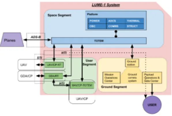
Fig. 4. Spot fire geo-referencing software 4. LUME system architecture
The LUME-1 system provides the communications services required by the FIRE-RS system to fulfill its mission objectives.
The LUME-1 system (see Architecture Scheme in Fig. 5) is composed of the elements below:
• The Space Segment (LUME-1 spacecraft), that will be based on a 2U CubeSat and will incorporate a TOTEM communications payload for servicing the deployed GDA/RT terminals or the UAV/CP payloads.
• The UVIGO Ground Segment, which will be composed of:
o a single Ground Station,
o a Mission Operations Control Center o a Payload Operations Center;
Fig. 5. LUME-1 System Architecture
In this case and in order to keep utilizing the same nomenclature that was used in the FIRE-RS system of system (to which this one belongs), the user segment for the LUME-1 system will be composed of the following elements:
• The GDA Remote Terminals (GDA/RT) that will be used within the GDS system for the GDA assets to communicate with the LUME-1 spacecraft and/or with UAVs that incorporate the UAV/CP-TOTEM payload.
• The UAV Communications Payload (UAV/CP), either in the Remote Terminal configuration (UAV/CP-RT) or in the TOTEM configuration (UAV/CP-TOTEM).
• The DPS system to which the data gathered from either the GDA assets or from the UAVs has to be forwarded.
The services to be provided to these users are the following:
• The Storage and Forward Communications Service and the Data Relay Service that is going to be provided to either the GDA/RT terminals or to the UAV/CP payloads, also in either of its possible configurations.
• The Remote Data Access Service to be provided to the DPS system in order for its data processing center to access the data gathered either from the GDA assets or from the UAVs. In addition, the LUME-1 Spacecraft also implements ADS-B capabilities, therefore the LUME-1 Spacecraft will implement the mechanisms required to receive ADS-B messages from planes or UAV, these messages will be downloaded to the ground stations and deliver to the ADS-B Clients later on through the payload Operations center.
4.1. LUME configuration
Following the CubeSat Design Specification, LUME1 is a 2 Units (3U) nanosatellite architecture -based on commercial off-the-shelf (COTS) components, composed of eleven subsystems, whose configuration is
constrained by the available volume, mass, derived optical payload accommodation, navigation strategy and thermal survivability.
The principal characteristics of the LUME-1 satellite (see Fig. 6) are:
• Type of Satellite: 2U Cubesat • Type of Orbit: SSO 550 Km • Orbital period: approx. 90 Min
• Communications band: UHF/S-Band/L-Band
• Launch: Q4 2018. Soyuz
• Payload M2M - SDR TOTEM + HUMSAT • Test Area: SUDOE Territory (Galicia
(Spain) + North of Portugal).
The main HW and SW developments of the University of Vigo in the LUME-1 satellite are:
• Satellite: New 2U system definition • Software: OBSW implementing CCDS, and
PUS for a RTOS environment: • Payload: TOTEM SDR
• Communications subsystem to be integrated in UAVS to communicate to LUME-1 satellite
• New Ground Station based on SDR (USRP).
Fig. 6. LUME-1 CAD Model
Fig. 7 shows the Flight Model of LUME satellite after the successful completions of the thermal-vacuum and the vibration tests (respectively Fig. 8 and Fig. 9) executed following the ECSS standards.
Fig. 7. Flight Model of LUME satellite
Fig. 8. LUME-1 satellite inside the thermal-vacuum chamber at Netherland Space CXentre
Fig. 9. Execution of the Vibration test of LUME-satellite at Netherland Space Centre. 4.2. Totem SDR Payload
The main functionality of LUME-1 satellite is tp provide a communication channel between worldwide
located infrared sensors detecting potential fires the control centre located at LAAS in Toulouse using storage-and-forward and/or data relay schemes.
TOTEM (Fig. 10) is a high performance SDR platform designed for nanosatellites, which includes a UHF front end. Totem has been developed at Vigo University and Alén Space (University of Vigo Spin-off Company) is currently commercially manufacturing.
Fig. 10. TOTEM Payload
TOTEM-Motherboard (Fig. 11) is the control unit and the RF transceiver while TOTEM-UHF-Frontend (Fig. 12) is an external UHF front-end piggyback board. An embedded Linux and a wide frequency range transceiver allow the user to fully cover most used nanosatellite frequency bands and quickly deploy multiple SDR applications.
The main characteristics of TOTEM are: • SDR+UHF front end platform
o 5W@30dBmin437MHz
• SDR tunable from 70 MHz to 6GHz • UHF front end as a piggy back board
o Unregulated voltage supplies from EPS and 3V3
o Multiple GPIOs and DACs • Embedded Linux
• Multiple interfaces: CAN, UART, Ethernet • PC/104standard
• Physical properties
o Mass: 131 g (shielding included)
o Dimensions: 89.3 mm x 93.3 x
13.9 mm • Power consumption:
o ~5W@30dBm output power
o <2W in RX mode
o 1.36 W with front end OFF
Fig. 11. Totem-Motherboard
Fig. 12. UHF Front-end 5. UAVs system
For the integration of sensors in UAV systems, the vehicle selected to test is the X8 Skywalker delta wing. It’s a COTS (Commercial Off-The-Shelf) vehicle, modified at the LSTS (University of Porto), which has been used by the LSTS on various types of operational scenarios in previous project.
The vehicle's propulsion system is an electrical motor to provide reliable and sufficient power to take-off, climb, and maintain flight at expected mission altitudes. In this vehicle have been integrated different sensors, including a frontal camera and a belly camera with different purposes ranging from mapping to video streaming, beside elements related to navigation, communication, energy management and image collection.
LSTS, in conjunction with the University of Vigo, was able to successfully integrate the SDR with its X8 UAV (Fig. 13). Preliminary tests to the communication link were done during these flights having a ground station simulator at Vigo receiving station.
Furthermore, the LSTS conducted UAV flights in order to collect infrared geo-referenced images were tested in order to the obtaining of the imaging analysis and data processing defined in next section.
Fig. 13. UAV-X8 vehicle with SDR transmission and UHF antenna installed, during field trials 6. Data processing system: propagation model
The aim of the project is becoming in a useful tool for Emergency Agents in the wildfire-fighting. For this, from data providing by the previous systems, a Fire Mapping Software is developed to simulated the propagation of the fire. This model is update from the real time data obtaining from the UAVs after the alarm given by the land sensor, and all the information is transmitting using the SDR picosatellite transmission.
In fact, the Data Processing Centre embeds the Situation Assessment and Observation Planning (SAOP) system as a tool to gather the output information relative to the fire and integrates them within a consistent representation of the situation. It also plans the observations to be made by the UAVs to fulfil operator’s information requests.
The SAOP system is made of the following components (see Fig. 14):
• The Fire mapper
• The Fire state assessment and prediction • The Observation trajectory planning, which
defines the trajectories to be achieved by the UAVs
Fig. 14. Fire data processing system architecture From the data processing, a fire model was implemented to predict the propagation and give to the
‘users’ (Emergency Units) pre-information to assess the future evolution of the situation.
Many fire models have been devised since the late sixties with are reviewed in depth by Sullivan [5, 6]. A common understanding model for fire evolution is based on predicting the Rate of Spread of the fire, taking into account the environmental variables as input (kind of vegetation, that is, fuel type, humidity, wind, terrain slope, etc.). In this project it is implemented a recent extension of the Rothermel model [7].
A sample of the software implemented and fire prediction is shown in Fig. 15.
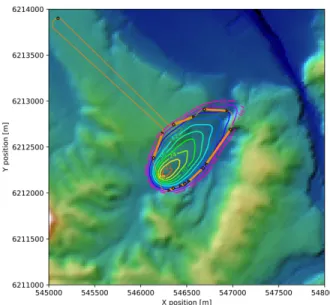
Fig. 15. Fire propagation in a mountainous area Beside this, prediction obtaining is also using to plan the observation trajectory for the UAVs (Fig. 16). To maximize the precision and timeliness of the gathered information, first developments on the SAOP sub-system have consisted in defining a nearly real-time fire propagation model that integrates fire observations, wind forecasts, the terrain topography and the properties of the vegetation. On the basis of this propagation model, a system that plans the fire observation trajectories for the UAVs has been developed: it specifies the trajectory to execute within the flyable time range (Fig. 17).
Fig. 16. UAV trajectory recalculation based on fire estimation propagation
Fig. 16. UAV planned and recalculated trajectory over a simulated fire situation
The position of the fire front is represented by the concentric curves, with the time denoted in minutes from the ignition. The UAV takes off from a position located on the top-left (north west) corner of the terrain: thick orange straight segments correspond to the parts of the trajectory where the UAV is actively taking footage of the fire (observation trajectories), while thin orange curves describe the trajectory that relies two observation segments.
8. Conclusions
The main conclusion of the Wildland Fire Remote Sensing (FIRE-RS) project is that implements an innovative system for prevention, detection and mapping of wildland fires.
This objective is achieved through the synergy of four technologies: infrared land sensors, picosatellites, UAVs and real time data processing, providing centralized access to relevant information for the emergency departments to apply decision-making protocols. Through this project, proving these integrated technologies, it is provided to the emergency agencies
an innovative tool for detecting and managing fire: almost real-time information, GPS positioning, fire perimeter, infrared images, propagation prediction and performance protocols.
Acknowledgements
Project funded by the Interreg Sudoe Programme through the European Regional Development Fund (ERDF): FIRE-RS project code: SOE1/ P4/E0437. References
[1] A. Guerra, A. S. Ferreira, M. Costa, D. Nodar-López, F. Aguado-Agelet, Integrating small satellite communication in an autonomous vehicle network: A case for oceanography, Acta Astronautica 145 (2018) 229-237.
[2] M. Denham and K. Laneri, Using efficient parallelization in Graphic Processing Units to parameterize stochastic fire propagation models, Journal of Computational Science 25 (2018) 76-88. [3] A.A. Kuleshov, E.E. Myshetskaya, S.E. Yakush,
Numerical simulation of forest fire propagation based on modified two-dimensional model, Mathematical Models and Computer Simulations 9-4 (2017) 9-437-9-49-47.
[4] C.J. Min, S.S. Hyun, H.O. Jae, D.E. Yang, Allocation of infrared imaging sensor for fire detection, Disaster Advances 7-2 (2014) 56-63. [5] A. Sullivan, A review of wildland fire spread
modelling 1990-present 1: Physical and quasi-physical models, International Journal of Wildland Fire (2009)
[6] A. Sullivan, A review of wildland fire spread modelling 1990-present 2: Empirical and quasi-empirical models, International Journal of Wildland Fire (2009)
[7] P. Andrews, M.G. Cruz, R. C. Rothermel, Examination of the wind speed limit function in the Rothermel surface fire spread model, International Journal of Wildland fire 22-7 (2013)