READ THESE TERMS AND CONDITIONS CAREFULLY BEFORE USING THIS WEBSITE.
https://nrc-publications.canada.ca/eng/copyright
Vous avez des questions? Nous pouvons vous aider. Pour communiquer directement avec un auteur, consultez la
première page de la revue dans laquelle son article a été publié afin de trouver ses coordonnées. Si vous n’arrivez pas à les repérer, communiquez avec nous à [email protected].
Questions? Contact the NRC Publications Archive team at
[email protected]. If you wish to email the authors directly, please see the first page of the publication for their contact information.
NRC Publications Archive
Archives des publications du CNRC
This publication could be one of several versions: author’s original, accepted manuscript or the publisher’s version. / La version de cette publication peut être l’une des suivantes : la version prépublication de l’auteur, la version acceptée du manuscrit ou la version de l’éditeur.
Access and use of this website and the material on it are subject to the Terms and Conditions set forth at
Parameters for consideration in performance-based fire resistance
design of floor assemblies
Sultan, M. A.
https://publications-cnrc.canada.ca/fra/droits
L’accès à ce site Web et l’utilisation de son contenu sont assujettis aux conditions présentées dans le site LISEZ CES CONDITIONS ATTENTIVEMENT AVANT D’UTILISER CE SITE WEB.
NRC Publications Record / Notice d'Archives des publications de CNRC:
https://nrc-publications.canada.ca/eng/view/object/?id=95e4c1fc-77fd-4c4f-a7e4-7bfc6886780d https://publications-cnrc.canada.ca/fra/voir/objet/?id=95e4c1fc-77fd-4c4f-a7e4-7bfc6886780d
Parameters for consideration in performance-based
fire resistance design of floor assemblies
Sultan, M.A.
A version of this paper is published in / Une version de ce document se trouve dans:
Proceedings of 5th AOSFST International Conference, Newcastle, Australia, Dec. 3-6, 2001, pp. 1-3
www.nrc.ca/irc/ircpubs
Parameters for Consideration in Performance-Based Fire Resistance Design of Floor Assemblies
Mohamed A. Sultan Fire Risk Management Program National Research Council of Canada
Ottawa, Ontario, Canada, K1A 0R6
ABSTRACT
With the advent of performance-based codes and performance-based fire safety design options, it is essential to determine the parameters that affect the fire resistance performance of assemblies. The results of twenty-three full-scale floor fire resistance tests are presented. Parameters investigated in this study include the effects of gypsum board screw spacing from board edges, insulation type, number of layers of gypsum board, joist spacing, resilient channel spacing, concrete topping, and structural load. The impact of these parameters on the performance-based fire resistance design of floor assemblies is provided.
INTRODUCTION
In recent years, countries around the globe have either already adopted performance-based codes, such as Australia and New Zealand, are working on this direction as in North America and Europe or taken a wait and see approach. Canada is expected to adopt objective-based building code by the year 2003. The current plans in Canada call for each of the building codes, fire code and pluming code to be published in one document with two major divisions – Division A and Division B. Division A will set out the objectives that the code addresses and the functional requirement (in qualitative terms) solutions must satisfy. Division B will set out the quantitative performance criteria with which solutions must comply and provide acceptable solutions. The parameters discussed in this paper will provide some guidance in the development of fire resistance objective-based and performance-based design solutions.
DESCRIPTION OF TEST ASSEMBLIES
Twenty-three floor assemblies, 4.8 m long by 3.9 m wide, were constructed. Three types of framing were used in this study: solid wood joist (38 mm thick by 235 mm deep), wood I-joist (240 mm deep) and steel C-joist (203 mm deep). The spacing for the joists and resilient channels in each assembly are given in Table 1 and Reference 1. Three types of insulation were used: either glass or rock fibre batts, 90 mm thick or cellulose fibre insulation sprayed wet, from 93 mm to 125 mm thick. Sub-floor used was Canadian softwood plywood (CSP) tongue and groove, 15.9 mm thick. The ceiling finish used in the assemblies was Type X gypsum board, 12.7 mm thick.
Assemblies with solid wood joists – Eleven insulated and non-insulated full-scale test assemblies were constructed using solid wood joists nominal 2x10 (38 mm by 235 mm) spaced 406 mm o.c. with one row of wood cross bracing, 19 mm by 64 mm, placed at the centre of the assembly between the joists.
Assemblies with wood I-joists – Eight insulated and non-insulated full-scale test assemblies were constructed using wood I-joists nominal 2x10 (38 mm by 240 mm) spaced 406 mm o.c.
2
Assemblies with steel C-joists – Four insulated and non-insulated full-scale test assemblies were constructed using wood I-joists nominal 2x8 (38 mm by 203 mm) spaced 406 mm o.c.
Assemblies were tested in accordance with CAN/ULC-S101-M89 that is similar to ASTM E119.
RESULTS AND IMPACT ON PERFORMANCE-BASED FIRE RESISTANCE DESIGNS
The results of the 23 full-scale fire resistance floor tests are summarised in Table 1 in which the fire resistance is provided for each assembly. The impact of the parameters studied on the performance-based fire resistance design are as follows:
1. The effect of screws location from board edges on fire resistance is significant. Assembly with screws located at 38 mm provide 50% higher fire resistance than assembly with screws at 10 mm from the board edges.
2. In assemblies with solid wood joists and a single-layer gypsum board ceiling finish, adding glass fibre insulation in the floor cavity reduced the fire resistance while adding either rock or cellulose fibre increased the fire resistance compared to non-insulated assembly. In assemblies with a double-layer gypsum board finish, adding either glass or rock or cellulose fibre in the floor cavity reduced the fire resistance compared to a non-insulated assembly.
3. For floor assemblies with wood I-joists and single layer gypsum board ceiling finish, adding either rock or cellulose fibre insulation in floor cavity increased the fire resistance compared to a non-insulated assembly.
4. In assemblies with Wood I-joist and double layer gypsum board finish, adding glass fibre insulation in the floor cavity reduced the fire resistance while adding rock fibre increased the fire resistance compared to a non-insulated assembly.
5. For floor assemblies with C-steel joists and a double-layer gypsum board ceiling finish, adding glass fibre insulation in the floor cavity reduced the fire resistance compared to a non-insulated assembly. 6. Assemblies with two layers of gypsum board with staggered joints provided a significant increase in
the fire resistance compared to an assembly with one layer of gypsum board.
7. For assemblies with wood-I-joist and a double layer of gypsum board, the effects of resilient channel spacing (400 mm o.c. versus 600 mm o.c.) were significant.
8. The effect of joist spacing (400 mm o.c. versus 600 mm o.c.) for assemblies with resilient channels was insignificant.
9. Adding concrete topping above the sub-floor for acoustical purposes reduced the fire resistance compared to assembly without concrete topping.
10. Fire resistance for floor assemblies increased with decrease of the applied load. Assemblies with restricted load provided higher fire resistance than those with maximum design load.
REFERENCES
1. Sultan, M.A., Seguin, Y.P. and Leroux, P. "results of fire resistance tests on full-scale floor assemblies", Internal Report No. 764, Institute for Research in Construction, 1998.
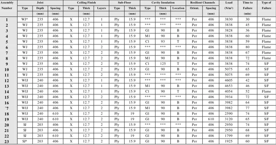
Table 1. Full-Scale Floor Assemblies Parameters and Fire Test Results
Assembly Joist Ceiling Finish Sub-Floor Cavity Insulation Resilient Channels Load Time to Type of Number Type Depth Spacing Type Thick Layers Type Thick Type Thick Location Orient. Spacing (N/m²) Failure Failure
(mm) (mm) (mm) (mm) (mm) (mm) (min)
1 WJ* 235 406 X 12.7 1 Ply 15.9 *** *** *** Per 406 3830 30 Flame
2 WJ 235 406 X 12.7 1 Ply 15.9 *** *** *** Per 406 3838 45 Flame
3 WJ 235 406 X 12.7 1 Ply 15.9 G1 90 B Per 406 3828 36 Flame
4 WJ 235 406 X 12.7 1 Ply 15.9 M1 90 B Per 406 3838 60 Flame
5 WJ 235 406 X 12.7 1 Ply 15.9 C1 93 T Per 406 3838 59 Flame
6 WJ 235 406 X 12.7 2 Ply 15.9 *** *** *** Per 406 3838 80 Flame
7 WJ 235 406 X 12.7 2 Ply 15.9 G1 90 B Per 406 3838 67 Flame
8 WJ 235 406 X 12.7 2 Ply 15.9 M1 90 B Per 406 3838 72 Flame
9 WJ 235 406 X 12.7 2 Ply 15.9 C1 125 T Per 406 3838 74 S/F
10 WJ 235 406 X 12.7 2 Ply 15.9 G1 90 B Per 406 5075 65 S/F
11 WJ 235 406 X 12.7 2 Ply 15.9 *** *** *** Per 406 5075 69 S/F
12 WIJ 240 406 X 12.7 1 Ply 15.9 *** *** *** Per 406 4605 42 S/F
13 WIJ 240 406 X 12.7 1 Ply 15.9 M1 90 B Per 406 4653 46 S/F
14 WIJ 240 406 X 12.7 1 Ply 15.9 C1 90 T Per 406 4054 52 Flame
15 WIJ 240 406 X 12.7 2 Ply 15.9 *** *** *** Per 406 3934 72 S/F
16 WIJ 240 406 X 12.7 2 Ply 15.9 G1 90 B Per 406 3982 64 S/F
`7 WIJ 240 406 X 12.7 2 Ply 15.9 M1 90 B Per 406 3982 77 S/F
18 WIJ 240 610 X 12.7 2 Ply 19 G1 90 B Per 406 2590 74 S/F
19 WIJ 240 610 X 12.7 2 Ply 19 G1 90 B Per 610 3120 65 S/F
20 SJ 203 406 X 12.7 2 Ply 15.9 *** *** *** Per 406 2950 74 S/F
21 SJ 203 406 X 12.7 2 Ply 15.9 G1 90 B Per 406 2950 68 S/F
22 SJ 203 610 X 12.7 2 Ply 19 G1 90 B Per 406 1799 69 S/F
23 SJ* 203 406 X 12.7 2 Ply 15.9 G1 90 B Per 406 1925 60 S/F
S/F - Structural Failure and Flame Penetration Per - Perpendicular to Wood-I-Joists X - Firecode C core Type X board C1 - Cellulose Fibre Insulation G1 - Glass Fibre Insulation M1 - Rock Fibre Insulation WIJ - Wood-I-Joist
WJ* - Gypsum Board Screw Spacing from Board Edges 10 mm
OSB - Oriented Strand Board Ply - Plywood *** - Null Value T - Top B - Bottom WJ - Wood Joist SJ - Steel Joist