Publisher’s version / Version de l'éditeur:
Metallurgical and Materials Transactions B, 35, 1, pp. 161-170, 2004-02-01
READ THESE TERMS AND CONDITIONS CAREFULLY BEFORE USING THIS WEBSITE. https://nrc-publications.canada.ca/eng/copyright
Vous avez des questions? Nous pouvons vous aider. Pour communiquer directement avec un auteur, consultez la
première page de la revue dans laquelle son article a été publié afin de trouver ses coordonnées. Si vous n’arrivez pas à les repérer, communiquez avec nous à PublicationsArchive-ArchivesPublications@nrc-cnrc.gc.ca.
Questions? Contact the NRC Publications Archive team at
PublicationsArchive-ArchivesPublications@nrc-cnrc.gc.ca. If you wish to email the authors directly, please see the first page of the publication for their contact information.
NRC Publications Archive
Archives des publications du CNRC
This publication could be one of several versions: author’s original, accepted manuscript or the publisher’s version. / La version de cette publication peut être l’une des suivantes : la version prépublication de l’auteur, la version acceptée du manuscrit ou la version de l’éditeur.
For the publisher’s version, please access the DOI link below./ Pour consulter la version de l’éditeur, utilisez le lien DOI ci-dessous.
https://doi.org/10.1007/s11663-004-0106-5
Access and use of this website and the material on it are subject to the Terms and Conditions set forth at
Simulation of flow in a continuous galvanizing bath : Part I. Thermal
effects of ingot addition
Ajersch, F.; Ilinca, F.; Hétu, J.-F.
https://publications-cnrc.canada.ca/fra/droits
L’accès à ce site Web et l’utilisation de son contenu sont assujettis aux conditions présentées dans le site LISEZ CES CONDITIONS ATTENTIVEMENT AVANT D’UTILISER CE SITE WEB.
NRC Publications Record / Notice d'Archives des publications de CNRC:
https://nrc-publications.canada.ca/eng/view/object/?id=4d0b9731-9124-469d-b996-b94b9569ef79 https://publications-cnrc.canada.ca/fra/voir/objet/?id=4d0b9731-9124-469d-b996-b94b9569ef79Simulation of Flow in a Continuous Galvanizing Bath:
Part I. Thermal Effects of Ingot Addition
F. AJERSCH, F. ILINCA, and J.-F. HÉTU
A numerical analysis has been developed to simulate the velocity and temperature fields in an indus-trial galvanizing bath for the continuous coating of steel strip. Operating variables such as ingot addition, line speed, and inductor mixing were evaluated in order to determine their effect on the velocity and temperature distribution in the bath. The simulations were carried out using high-performance computational fluid-dynamics software developed at the Industrial Materials Institute of the National Research Council Canada (IMI-NRC) in solving the incompressible Navier–Stokes equa-tions for steady-state and transient turbulent flow using the k-« model. Cases with and without temperature-dependent density conditions were considered. It was found that the strip velocity does not alter the global flow pattern but modifies the velocities in the snout, near the strip, and near the sink and guide rolls. At a low inductor capacity, the effect of induced mixing is small but is consid-erably increased at the maximum inductor capacities used during ingot-melting periods. When considering the thermal effects, the flow is affected by variations in density especially near the induc-tors and the ingot, while little effect is observed near the sheet-and-roller region. Thermal effects are also amplified when the inductor operates at high capacity during ingot melting. The simulations allow visualization of regions of varying velocity and temperature fields and clearly illustrate the mixed and stagnant zones for different operating conditions.
I. INTRODUCTION
T
HEdemand for coated steel products continues to expand beyond the traditional applications for auto bodies, household appliances, and structural components. Residential and indus-trial buildings are also finding galvanized construction mater-ials to be easy to use and cost-effective. However, the most important product in market value is the hot-dipped galvanized or galvannealed sheet destined for auto body manufacture. Corrosion resistance, ready-to-paint surface quality, weld-ability, and formability are some of the key characteristics required. Recent developments include stronger and thinner steels (interstitial free, dual phase, and Transformation Induced Plasticity (TRIP)) with thinner coatings.The modern hot-dip galvanizing operation is a complex metallurgical process where steel strips of various widths and thicknesses are continuously coated by rapid immersion in a zinc alloy bath operating at temperatures normally between 450 °C and 480 °C. Cold-rolled strip is first degreased, cleaned, and then heated in a reducing atmos-phere before being introduced into a liquid zinc bath at line speeds from 0.5 to 2.0 m/s. A main sink roll guides the strip to a depth of about 1 meter below the bath surface before exiting between two guide-stabilizer rolls. The aluminum contents in the bath vary generally from 0.10 to 0.30 wt pct, depending on the coating specifications of galvannealed (0.10 to 0.13 wt pct Al) or galvanized (0.14 to 0.20 wt pct Al) products. The dissolved aluminum preferentially reacts with the steel to form an inhibition layer of Fe2Al5rather than
forming iron zinc intermetallic compounds, which are much more fragile. Coatings vary in thickness from 10 to 15mm,
consisting of an inhibition layer (,1mm) covered by the Zn-Al alloy. Since the inhibition layer is much more ductile, it promotes adherence of the coating to the steel when the sheet is stamped and formed into the auto body components. The galvanizing process can, therefore, be considered to be a semicontinuous reactor stirred by the movement of the strip and the rolls. Makeup ingots of Zn-Al alloys are added to the bath to maintain a constant bath level and Al con-tent, as shown in Figure 1. Addition methods can vary, as was shown in a survey of different galvanizing operations,[1]
and Al utilization efficiency can be as low as only 50 pct. Bath instability due to temperature fluctuation can result in the precipitation of Fe-Zn-Al intermetallic phases, depending on the solubility limits of Fe and Al. Galvanneal operations generally produce a bottom dross of dphase (FeZn7), whereas
galvanizing operations generate a top dross of Fe2Al5. A review of the effect of bath chemistry on the solubility has been presented in several studies.[2,3,4]It has been shown
that the formation of the inhibition layer is very rapid (0.10 to 0.25 seconds) and requires a uniform supply of Al at the strip entry within the snout. Toussaint et al.[5] have shown
that the fluid dynamics affect the thickness of the inhibition layer. It becomes evident, therefore, that the flow fields and degree of turbulence in this critical zone of sheet con-tact with the bath are of great importance in analyzing the Al transport.
The transport of Al in the bath ideally consists of a con-vective transport from the solution to the coating surface. However, the entrainment of intermetallic particles is almost inevitable, and good bath management requires a min-imization of dross formation. Several previous studies have used water models to determine the flow field in these zones.[6,7,8]Numerical simulations[9–12]have also been carried
out to determine the variation of zinc flow and have resulted
METALLURGICAL AND MATERIALS TRANSACTIONS B REPRODUCED BY PERMISSION OF VOLUME 35B, FEBRUARY 2004—161 MINISTER OF SUPPLY AND SERVICES CANADA
F. AJERSCH, Professor, is with École Polytechnique de Montréal, Montréal, PQ, Canada H3C 3A7. F. ILINCA and J.-F. HÉTU, Research Officers, are with the Industrial Materials Institute, National Research Council, Boucherville, PQ, Canada J4B 6Y4. Contact e-mail: florin.ilinca@cnrc-nrc.gc.ca
162—VOLUME 35B, FEBRUARY 2004 METALLURGICAL AND MATERIALS TRANSACTIONS B
Fig. 1—Schematic of a continuous galvanizing bath.
in a much more detailed analysis. This has resulted in a much better understanding of the degree of mixing in the different regions of the bath. In Reference 13, a 1/5 scale water model was designed to validate the numerical solution previously carried out[9] as well as to quantify the degree
of turbulence at specific locations in the bath. Velocity fluctuations were measured with a laser Doppler velocime-ter to develocime-termine the degree of turbulence and were shown to be in good agreement, demonstrating that the numerical simulations can be carried out rapidly to illustrate a large range of flow parameters.
The purpose of the present article is to advance the under-standing of flow in the galvanizing bath, particularly relating to the movement of dross particles in a thermally influenced velocity field. The latest simulation techniques and high-speed processors can now handle very complex flow systems with a very large number of grid points, resulting in an extremely detailed prediction of flow. The previous simu-lations progressed from laminar- to turbulent-flow models, where the effect of line speed, strip width, and induction mixing have all been quantified for isothermal bath condi-tions operating at steady state. It has become clear that the flow is clearly three dimensional, due to the complex geo-metry of the immersed hardware. This still only simulates the condition for periods of the process when no makeup ingots are added to the bath. However, when ingots are added to replace the product layer deposited on the exit sheet, the bath can no longer be considered to be isothermal. During this period, the induction heating rate is increased to adjust to the heat demand of the melting ingot, thereby increasing temperature variations in the bath. The temperature at the inductor exit is higher and the region at the melting surface of the ingot is lower than the average bath temperature. Since the liquid-zinc alloy densities are very sensitive to the tem-perature variations, it is anticipated that temtem-perature variations in the bath would affect the overall flow due to natural convection, especially in regions where forced convection is small. This occurs in regions away from the moving strip and immersion rollers, which are significantly affected by the temperature variations.
This article shows the importance of these temperature variations on the flow within the bath resulting from the melting of an ingot as compared to the isothermal case. The bath configuration used in the study is the same as was used for the previously reported isothermal calculations.[10]Heat
losses through the pot sidewalls, bottom, and bath surface are taken into account in the heat balance, so that the over-all average bath temperature remains relatively constant at 460 °C. This information should be of significant impor-tance in defining the best procedures for making additions to the bath in order to minimize dross formation and entrain-ment. The spatial and temporal distributions of aluminum in the bath are presented in Part II of this study.
II. GOVERNING EQUATIONS
Flow inside the bath is described by the incompressible Navier–Stokes equations:
[1]
[2] where D/Dt 5 / t 1 u · = is the particular derivative,
g· (u) 5 (=u 1 =uT)/2 is the strain-rate tensor, ris the
density, mis the fluid viscosity, and g is the gravity. When buoyancy effects are neglected, the density is constant, and the gravity term generates just an additional hydrostatic pressure with no influence on the velocity. However, if the density depends on temperature, the gravity term is no longer constant. The usual approximation of buoyancy for small density variations is given by the Boussinesq approximation. Hence, the gravity term is considered as the perturbation from a reference value and the momentum equations become
[3] where r0is the density at the reference temperature T0, and
bis the thermal-expansion coefficient.
The turbulent viscosity (mT) is computed using the
stan-dard k-« model of turbulence:[14]
[4]
For this model, the turbulence quantities are the turbulence kinetic energy (k) and its dissipation rate («). The transport equations for k and « are
[5]
[6] where P is the shear production term, defined as
[7]
P(u) 5 mT Ñu: Ñu 1 ÑuT rD« Dt 5 Ñ m 1 mT s« Ñ« 1 C«1« k (P 1 G) 2 C«2r «2 k rDk Dt 5 Ñ m 1 mT sk Ñk 1 P 1 G 2 r« mT5 rCm k2 « r0Du Dt 5 2Ñp 1 Ñ 2 (m 1 mT)g (u) 2 r0 g b(T 2 T0) Ñ u 50 rDu Dt 5 2 Ñp 1 Ñ 2(m 1 mT)g (u) 1 rg
METALLURGICAL AND MATERIALS TRANSACTIONS B VOLUME 35B, FEBRUARY 2004—163
and G accounts for the effect of the buoyancy on the pro-duction of turbulence:
[8] The constants sk, s«, C«1, C«2, and Cm are as follows:[14]
sk51.0, s«51.3, C«l51.44, C«251.92, Cm50.09
Increased robustness of the solution algorithm is obtained by solving the turbulence equations for the logarithms of turbulence variables.[15]In such a way, the positivity of
tur-bulence variables is enforced, resulting in increased accuracy and a faster solution approach.
The temperature (T) is obtained by solving the energy equation:
[9] where cp is the specific heat, and l is the thermal
con-ductivity. The turbulent thermal conductivity (lT) is
com-puted from
[10] where PrTis the turbulent Prandtl number, considered equal
to unity.
Boundary Conditions
Boundary conditions for the momentum equations are spec-ified on the strip and the inlet section (inductor inlet), as well as on the solid boundaries (walls). The inductor inlet has been modeled using a flow rate correlated to the inductor power (400 kW at maximum capacity). The influence of the inductor itself has been introduced through Dirichlet bound-ary conditions (prescribed velocities). Boundbound-ary conditions imposed on the Navier–Stokes equations are then as follows:
[11]
A velocity wall function is applied on all mobile and immo-bile surfaces, e.g., the bath walls, strip, rollers, snout, and arms. The wall function correlates the tangential stresses in the boundary layers to the relative tangential velocity.
[12] where [13] y1 5 rCm1/4kw1/2y m U15 y1 , y1, yc 1 1 kln(Ey 1 ) , y1 $ yc 1 tw 5 2rCm 1/4 k w 1/2 U1 (u 2 uw) where uw 50 on Gwall uw 5 ustrip on Gstrip u n 50
u 5 Uinductor on Ginductor inlet
2(m 1 mT)g (u 2 uw) n 2 pn 5 tw on Gwall and Gstrip
lT 5mTcp PrT rcpDT Dt 5 Ñ (l 1 lT)ÑT G 5 mT PrT bg ÑT
Here, uwis the velocity at the wall, y is the distance between
the computational boundary and the wall, kis the Von Karman
constant (k50.41), and E is a roughness parameter (E 5 9.0 for smooth walls). The normal derivative of the turbulence kinetic energy is set to zero near the wall, so that its values at the boundary points kware computed implicitly. Then, the
turbulence dissipation at the wall is obtained by using
[14]
The velocity is constrained to be tangent to the wall by imposing the normal velocity to be zero. It is also assumed that the position of the top surface remains at the same height. The regions of the top surface inside the snout and close to the strip exit are considered as free surfaces, and only the normal component of the velocity is set to zero. The remain-ing regions on the top surface were considered to be covered by solidified zinc oxide and were treated as solid walls.
The temperature boundary conditions at a wall are enforced by a temperature wall function.[16]The procedure is similar
to that used for the velocity and consists of imposing a wall heat flux, given by
[15]
[16]
where Twis the wall temperature and T
1is a function of y1
(Ignat et al.[16] provides more details). When the ingot is
present in the bath, Tw on the ingot surface is considered
equal to the melting temperature (Tw5420 °C). On the bath
walls, in addition to the temperature wall function, boundary conditions take into account the heat loss through walls. This is modeled using a convection boundary condition:
[17] where hcis a heat-transfer coefficient and Tais the ambient
temperature. The wall function coupled with the convection heat transfer through walls results in a wall heat flux given by [18] in which h is an equivalent heat-transfer coefficient,
h 5 hThc/(hT1 hc).
III. FINITE-ELEMENT SOLUTION
The global system of equations is solved in a partly seg-regated manner. Global iterations are carried out for the momentum-continuity, turbulence, and energy equations. Subit-erations of turbulence transport equations are also used to accelerate the overall convergence of the iterative process.[17]
The Navier–Stokes and scalar transport equations are solved using the streamline-upwind Petrov–Galerkin (SUPG) method.[18] This method contains additional stabilization
terms, providing smooth solutions to convection-dominated flows. The SUPG method also deals with velocity-pressure coupling, so that equal-order interpolation results in a stable numerical scheme. This allows the use of simple linear
qw 5 h(T 2 Ta) qw 5 hc(Tw 2 Ta) hT 5 rcpCm1/4kw1/2 T1 qw 5 hT (T 2 Tw) «w5 Cm 3/4 k w 3/2 ky
164—VOLUME 35B, FEBRUARY 2004 METALLURGICAL AND MATERIALS TRANSACTIONS B
Table I. Computational Configurations
Sheet Sheet Case Ingot Present Velocity (m/s) Width (mm)
1 no 1.75 1500
2 yes 1.75 1500
3 no 3.0 1500
4 yes 3.0 1500
Fig. 2—Computational domain.
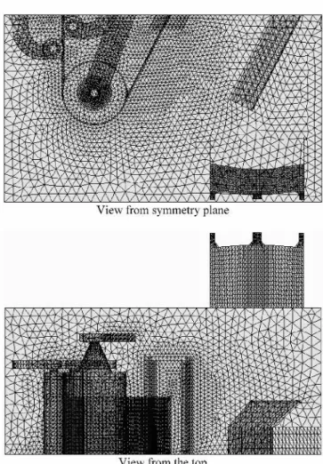
Fig. 3—Finite-element discretization.
elements for all variables. A more detailed account of the numerical method and the algorithm used has been recently presented by Ilinca et al.[19]
IV. BATH CONFIGURATIONS
The present methodology is applied to the solution of flow and heat transfer inside a galvanizing bath. The configurations considered are summarized in Table I. Computations of velo-city and temperature fields were performed for (1) forced-convection heat transfer (no temperature-dependent terms in the momentum equation) as well as for (2) mixed-convection heat transfer. In the second case, the Boussinesq approxima-tion was used to describe the density variaapproxima-tions upon tem-perature. Calculations do not take into account differences in density due to different contents of aluminum between the melting ingot and the bath. The forced-convection case was computed for steady-state conditions, while transient solutions were obtained for mixed convection. For the transient case, solutions were obtained over a 20-minute time frame using the forced-convection solution as an initial condition. After 20 minutes, the solution exhibits very small changes and can be considered as fully developed. In this simulation, the exter-nal surface of the ingot at 420 °C remains unchanged for the period of calculation. In actual fact, the ingot melts during this period and the thermal effect of the ingot boundary condition becomes progressively smaller, ending at a thermal condition of no ingot present after 20 minutes.
The computational domain is illustrated in Figure 2. All computations were carried out using the IMI computational fluid-dynamics solver. The computational domain was dis-cretized using four-node tetrahedral finite elements. The mesh has 64,522 nodes and 366,949 elements. Figure 3 illustrates the finite-element discretization. Because the bath geometry is symmetrical, only half of the domain was considered. Velo-cities are specified at the inlets from the inductors. Simulations were done for the cases with and without the presence of an ingot. When the ingot is present in the bath (cases 2 and 4), the inductor power is considered to be at 100 pct. The induc-tor power is decreased to 20 pct when no ingot is present in the bath (cases 1 and 3). The solution was considered con-verged when a tolerance of 1026
was achieved for all variables and that for both the relative correction of the solution (norm of the solution change from one iteration to another divided by the norm of the solution) and the relative residual (norm of the residual divided to the norm of the initial residual).
The initial steady-state temperature in the bath is consid-ered to be 460 °C. The flow rate and temperature increase through the inductors is as from the Bethlehem Steel Burns Harbor operation.[10]The liquid zinc from the inductors enters
the bath at 0.75 m/s and is heated to 20 °C above the outlet temperature when 100 pct of the power is considered and at
0.4 m/s and an 8 °C temperature increase when only 20 pct of the inductors’ power is used. When the ingot is present, the ingot surface is assumed to be at the melting tempera-ture, which is 420 °C. Temperature gradients are, therefore, higher in the presence of an ingot in the bath.
Constant material properties have been used to perform the analysis. The material properties for Zn 1 0.15 pct Al at a temperature of 460 °C are as follows:
a. density: r56600 kg/m3;
METALLURGICAL AND MATERIALS TRANSACTIONS B VOLUME 35B, FEBRUARY 2004—165
Fig. 4—(a) and (b) Case 1 (no ingot): velocity vectors on the left inductor plane.
c. specific heat: cp5512 J/kg·K;
d. thermal conductivity: l560 W/m·K; and e. thermal-expansion coefficient: b51.666·1024
K21
V. NUMERICAL RESULTS
Figure 4 shows velocity vectors on the plane through the left-inductor exit with no ingot present. The solution of Figure (a) corresponds to the forced-convection case, while solution of Figure 4(b) considers also the influence of the
temperature on the velocity using the Boussinesq term, incor-porating temperature-induced density variations. A natural convection-type flow is present when the Boussinesq term is considered, with the higher-temperature liquid from the inductor going upward and then the flow going downward close to the symmetry plane because of the cooling near the top surface. Figure 5 shows the results of case 2, where the melting ingot is present in the bath and with the inductor power at 100 pct. Comparing the solutions of Figure 5(a) for
Fig. 5—(a) and (b) Case 2 (with ingot): velocity vectors on the left induc-tor plane.
166—VOLUME 35B, FEBRUARY 2004 METALLURGICAL AND MATERIALS TRANSACTIONS B
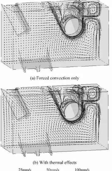
Fig. 6—(a) and (b) Case 1 (no ingot): velocity vectors on a plane parallel to the symmetry plane.
forced convection only and of Figure 5(b) with a temperature-dependent density, we can observe that natural convection effects are much more important than for the case with no ingot present.
Velocity vectors in a plane parallel to the symmetry plane for the same conditions (cases 1 and 2) are shown in Figures 6 and 7. When no ingot is present, the natural convection term makes little difference in this plane, since only the liquid zinc cooled on the left wall moves down-ward because of the higher density (Figure 6(b)). In both cases, thermal effects are localized near the inductors and ingot and are very small near the sheet-and-roller region. Figure 8 shows the velocity vectors for a higher sheet velocity (case 4). Comparing this solution with the results of Figure 7(b), we can conclude that the flow near the ingot is dominated by thermal effects, whereas close to the sheet and rolls, the flow is determined by the move-ment of the steel sheet.
Figure 9 illustrates the temperature distribution with and without natural convection. When only the forced convection is considered, the cold liquid zinc remains in a narrow region close to the melting ingot. If the temperature-dependent density
Fig. 7—(a) and (b) Case 2 (with ingot): velocity vectors on a plane par-allel to the symmetry plane.
is taken into account, the colder zinc close to the ingot has a higher density and, therefore, flows to the bottom of the bath. The temperature distribution inside the bath becomes stratified, with the colder zinc on the bottom of the bath and a higher temperature near the top surface. When the ingot is present in the bath, the temperature also has a major influence on the flow, as can be observed from Figure 10. For case 2, the low-velocity regions (zinc velocity lower than 0.01 m/s) are illustrated with and without thermal effects. In the absence of the temperature-induced flow, we observe a large low-velocity region near the ingot basket, whereas the influence of the sheet and rolls is similar for both the no-ingot and ingot-present cases. However, when considering the temperature effect on the flow, the high-temperature gradients near the ingot have a large influence on the liquid-zinc movement.
Figures 11 through 13 present the temperature and verti-cal velocity distribution along lines parallel to the symmetry and top planes for the configuration of case 2 with mixed convection heat transfer. Locations range from close to the ingot, z 5 0.444 m (Figure 11), with an intermediate loca-tion at z 5 1.035 m (Figure 12), and then close to the induc-tor, z 5 1.625 m (Figure 13). In each figure, five different
METALLURGICAL AND MATERIALS TRANSACTIONS B VOLUME 35B, FEBRUARY 2004—167
Fig. 8—With ingot and thermal effects: velocity vectors for higher sheet speed (case 4).
Fig. 9—Case 2 (with ingot): iso-temperature surface (smaller than 458 °C).
vertical locations are plotted. In Figure 11, a temperature stratification is observed with higher temperatures on the top layers. Sharp vertical velocity gradients are recovered near the moving strip and rollers, while the effect of the
ingot is clearly seen at x , 20.9 m. The temperature drops in this region with the smaller temperature for y 5 21.17 m, corresponding to the bottom part of the ingot. The max-imum downward velocity as a result of the buoyancy and the lowest temperature are observed at the same location (y 5 21.17 m and x 5 21.1 m). For the intermediate section, at z 5 1.035 m (Figure 12), the temperature field is clearly stratified, while the vertical velocity is more important near the strip and under the sink roll. The temperature differ-ence between the lower and upper layers varies from 5 °C on the ingot side (negative x) to 1 °C on the highly mixed strip region. This is in good agreement with experimental results of temperature variations in the bath, carried out by Anderson et al.[20]on a 190-ton bath, on which they observed
a temperature variation of 4 °C to 5 °C. Figure 13 shows the solution on a plane closer to the inductor. Flow from the inductor generates the two zones of important heating at x 5 21.7 m and x 5 20.7 m. Heating is more pronounced for y 5 21.62 m and y 5 21.17 m, sections which are just above the inductor outlet, resulting in a more pronounced upward buoyancy flow. The section at y 5 22.08 m shows little influence from the inductor, as it is placed below the level of the inductor outlet, while the temperature on the top layer (y 5 20.25 m) becomes more uniform as a result of mixing and heat diffusion.
168—VOLUME 35B, FEBRUARY 2004 METALLURGICAL AND MATERIALS TRANSACTIONS B
Fig. 11—(a) Temperature distribution and (b) vertical velocity distribution for case 2 at 0.444 m from the symmetry plane
VI. DISCUSSION
The computed results for the specific cases illustrated in this study show that forced-convection flow is controlled principally by the movement of the immersed hardware and the moving strip in the region of the bath where the tem-perature gradients are the smallest, assuming that the entering
strip and average bath temperatures are the same. Large tem-perature variations were observed for the condition during ingot melting as a result of the large difference in temper-ature between the bath and the melting point of the ingot and because of the additional heat introduced by the induc-tors that is required for melting and maintaining the bath temperature at an average level of 460 °C. Flow in this region
Fig. 12—(a) Temperature distribution and (b) vertical velocity distribution for case 2 at 1.035 m from the symmetry plane.
METALLURGICAL AND MATERIALS TRANSACTIONS B VOLUME 35B, FEBRUARY 2004—169
Fig. 13—(a) Temperature distribution and (b) vertical velocity distribution for case 2 at 1.625 m from the symmetry plane.
is dominated by a very significant contribution from the natural convection. The buoyancy-induced velocity has a magnitude of about 0.1 m/s, similar to the upward velocity of the heated liquid from inductors, while the velocity mag-nitude near the moving strip and rolls is about 0.2 m/s.
It can be clearly observed that the two distinct regimes of operation consist of an ingot-melting period lasting about
20 minutes and a period when no ingot is present. For the period when no ingot is present, the bath flow can be rea-sonably well simulated by considering only forced convec-tion for momentum and heat transfer. However, when an ingot is present, the variations in flow, particularly in the melting zone, cannot be adequately simulated without con-sidering the coupled effects of forced and natural convec-tion using the Boussinesq relaconvec-tion. Figures 4 and 5 clearly show the differences in the velocity field between these two distinct periods of operation. When the strip speed is increased to a higher value, as shown in Figure 8 for case 4, the flow field in the ingot melting zone is very similar to the case for the lower strip velocity, showing the predominant effect of natural convection in this region. When the tem-perature field is compared for the two different cases, the simulation shown in Figure 9 demonstrates the necessity to include the Boussinesq term. This temperature effect is equally dramatic in Figure 10, where the regions of the bath moving at velocities smaller than 0.01 m/s are represented in three-dimensional solid volumes. The volume including natural convection is considerably smaller than the forced-convection-only case. If these volumes can be considered to be equivalent to zones that are relatively stagnant, dross particles (Fe2Al5) would tend to migrate from the ingot
melting zone to a region below the sink roll and toward the bottom of the front of the bath. These velocities would define the movement of small entrained particles already in sus-pension in the bath, whereas the temperature variations con-tribute an additional factor beyond the thermally induced flow. Due to the sensitivity of the solubility of aluminum and iron in the bath as a function of temperature, moving particles of Fe2Al5can either grow by continued precipita-tion or dissolve in different temperature zones of the bath.
VII. CONCLUSIONS
Numerical simulations of the velocity and temperature distribution of a typical galvanizing bath have been carried out using a finite-element analysis. The results show that it is essential to include temperature-induced flow (natural con-vection) in addition to the forced convection, in order to achieve a realistic representation of the movement of liquid zinc in the bath. The temperature-induced flow is very impor-tant during the period of ingot melting, especially in the region of ingot immersion, when the induction heaters are operating at maximum capacity. For the period when no ingot is present, these thermal effects are much smaller, since the inductors operate at only 20 pct of their maximum heat input. The steel strip and roller movement determines the nature of the flow in the region where these components are in con-tact with the liquid zinc. Variations in strip velocity will modify the velocities near the inlet and outlet of the snout, at the edges of the strip, and at the front wall of the bath.
ACKNOWLEDGMENTS
The authors acknowledge particularly Dr. F.E. Goodwin, the International Lead Zinc Research Organization (ILZRO), and the industrial sponsors for funding this project. The authors also acknowledge the contribution of Michel Perrault in creating the bath mesh for the simulation.
170—VOLUME 35B, FEBRUARY 2004 METALLURGICAL AND MATERIALS TRANSACTIONS B
REFERENCES
1. S. Bélisle, S.L. Boston, G.G. Brummit, and H. Guttman:
GALVA-TECH ‘92,1992, pp. 55-61.
2. I. Linares, J.B. Guillot, A. Rist, O. Dobelle, P. Picard, T. Moreau, P. Abed, D. Cucheval, and R. Nicolle: GALVATECH ‘95, 1995, pp. 657-61. 3. M. Dauzot, F. Stouvenot, and T. Moreau: GALVATECH ‘92, 1992,
pp. 449-54.
4. N.-Y. Tang: Mater. Sci. Technol., 1995, vol. 11, pp. 870-73. 5. P. Toussaint, L. Segers, R. Winand, and M. Dubois: GALVATECH ‘98,
1998, pp. 141-46.
6. M. Gagné, A. Paré, and F. Ajersch: 84th Galvanizers Association
Meeting,Algonac, MI, 1992, pp. 142-63.
7. M. Iguchi, J. Kurobe, S. Matsubara, Z.-I. Morita, and K. Nakamoto:
Testu-To-Nagané,1995, vol. 81, pp. 733-38.
8. C. Binet and F. Ajersch: GALVATECH ‘98, 1998, pp. 648-53. 9. A. Paré, C. Binet, and F. Ajersch: GALVATECH ‘95, 1995, pp. 695-706. 10. F. Ajersch, C. Binet, F.E. Goodwin, K.S. Turke, and P.S. Kolisuyk:
GALVATECH ‘98,1998, pp. 642-47.
11. M. Gagné and M. Gang: GALVATECH ‘98, 1998, pp. 90-95. 12. K. Otsuka, M. Arai, and S. Kasai: GALVATECH ‘98, 1998,
pp. 96-101.
13. C. Binet, F. Ajersch, and R.T. Bui: Computer Applications in Metals
Processing,40th Annual Conf. of Metallurgists of CIM, Montreal, Canada, 2001, pp. 115-26.
14. B.E. Launder and D.B. Spalding: Mathematical Models of Turbulence, 6th ed., Academic Press, London, 1972.
15. F. Ilinca and D. Pelletier: AIAA J.,1998, vol. 36, pp. 44-50.
16. L. Ignat, D. Pelletier, and F. Ilinca: 34th Aerospace Sciences
Meet-ing & Exhibit,Reno, NV, 1996, paper no. AIAA 96-0607. 17. F. Ilinca and J.-F. Hétu: Int. J. Num. Meth. Fluids, 2000, vol. 34,
pp. 729-50.
18. L.P. Franca and S.L. Frey: Comp. Meth. Appl. Mech. Eng.,1992,
vol. 99, pp. 209-33.
19. F. Ilinca, J.-F. Hétu, and F. Ajersch: Numerical Heat Transfer, Part A:
Applications,2003, vol. 44, pp. 463-82.
20. N. Anderson, N.Y. Tang, and R.S. Patil: 88th Galvanizers Association