HAL Id: cea-01272817
https://hal-cea.archives-ouvertes.fr/cea-01272817
Submitted on 11 Feb 2016HAL is a multi-disciplinary open access archive for the deposit and dissemination of sci-entific research documents, whether they are pub-lished or not. The documents may come from teaching and research institutions in France or abroad, or from public or private research centers.
L’archive ouverte pluridisciplinaire HAL, est destinée au dépôt et à la diffusion de documents scientifiques de niveau recherche, publiés ou non, émanant des établissements d’enseignement et de recherche français ou étrangers, des laboratoires publics ou privés.
Chemical modelling of Alkali Silica reaction: Influence
of the reactive aggregate size distribution
Stéphane Poyet, Alain Sellier, B. Capra, G. Foray, J.-M. Torrenti, H. Cognon,
E. Bourdarot
To cite this version:
Stéphane Poyet, Alain Sellier, B. Capra, G. Foray, J.-M. Torrenti, et al.. Chemical modelling of Alkali Silica reaction: Influence of the reactive aggregate size distribution. Materials and Structures, Springer Verlag, 2007, 40 (2), pp.229-239. �10.1617/s11527-006-9139-3�. �cea-01272817�
Final draft of the article:
“Chemical modelling of Alkali Silica Reaction: Influence of the
reactive aggregate size distribution.”
Published in Materials and Structures. The final publication is
available at
link.springer.com
.
Chemical modelling of Alkali Silica Reaction:
Influence of the reactive aggregate size distribution
S. Poyet1, A. Sellier2, B. Capra3, G. Foray4, J.-M. Torrenti5, H. Cognon6 and E. Bourdarot7 (1) CEA Saclay – DEN/DANS/DPC/SCCME/LECBA – 91191 Gif sur Yvette, France
(2) LMDC, UPS - INSA Toulouse, 135 avenue de Rangueil, 33077 Toulouse cedex 4, France (3) Oxand SA, 36b avenue Franklin Roosevelt, 77210 Avon, France
(4) Université Lyon 1 - L2MS PETRA GC – 82 boulevard Niels Bohr – 69622 Villeurbanne cedex, France (5) IRSN – BP 17, 92262 Fontenay aux Roses Cedex, France
(6) EdF/DER - Les Renardières, Route de Sens, Ecuelles - 77818 Moret sur Loing, France (7) CIH - Savoie Technolac, 73373 Le Bourget du Lac, France
ABSTRACT
This article presents a new model which aims at the prediction of the expansion induced by Alkali Silica Reaction (ASR) and the description of the chemical evolution of affected concretes. It is based on the description of the transport and reaction of alkalis and calcium ions within a Relative Elementary Volume (REV). It takes into account the influence of the reactive aggregate size grading on ASR, i.e. the effect of the simultaneous presence of different sized reactive aggregates within concrete. The constitutive equations are detailed and fitted using experimental results. Results from numerical simulations are presented and compared with experiments.
RÉSUMÉ
Cet article présente un modèle qui a pour but la prédiction du gonflement induit par la réaction alcali-silice et la description de l’évolution chimique des bétons affectés. Il est basé sur la description du transport et de la réaction des alcalins et des ions calcium dans un Volume Elémentaire Représentatif. Il permet notamment de tenir compte de l’influence de la granulométrie réactive, c'est-à-dire de l’influence de la présence simultanée de granulats réactifs de différentes tailles dans le béton. Les équations constitutives du modèle sont détaillées puis calées à partir de résultats expérimentaux. Les résultats des simulations numériques sont présentés et comparés aux valeurs expérimentales.
1. INTRODUCTION
Alkali silica reaction (ASR) is a world wide known concrete pathology. It is due to chemical reactions between amorphous or poorly crystallized silica contained within reactive aggregates and ions from the pore solution of concrete (hydroxyls, alkalis and calcium ions) [1][2]. It leads to progressive destruction of reactive aggregates and precipitation of reaction products called “gels” whose composition may vary depending on local chemical equilibrium [3][4]. ASR affected concrete structures exhibit cracking, displacements, structural deformations, pop-outs and reduction in mechanical performances. Service of structures may be severely affected. Gels are usually supposed to be the main cause of the induced swelling and degradations.
After more than 60 years of research, the knowledge gained on reaction mechanisms has allowed researchers and recommendation committees to provide rules to prevent new ASR cases [5][6]. Unfortunately, till now there has been no way to stop the reaction or to cure an affected structure. There are many ASR affected structures around the world for which periodical repairs and preventive maintenance policies represent on going costs. Their managers need predictive tools to determine rate and end value of swelling in order to determine frequency, effectiveness of maintenance operations and effective economic life of the structure. The aim of this paper is to develop a numerical tool based on the
supposed chemical mechanisms of ASR which is able to reproduce the behavior of affected concretes and to help predicting the evolution of ASR induced swelling. The modeling has also to take account of the influence of the reactive aggregates dimension and size grading on ASR.
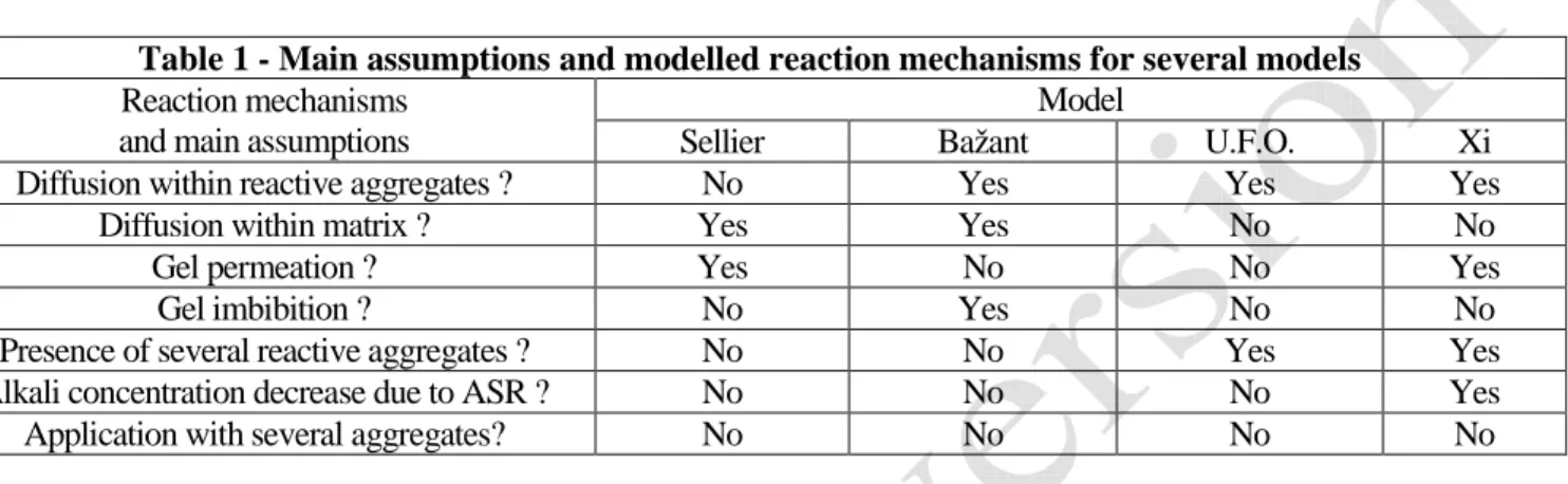
Among the vast literature about ASR, there are only a few models which are able to take account of the influence of the reactive aggregate dimension, for example [7][8] the U.F.O. model [9][10] and [11]. All of them study a Relative Elementary Volume made of a reactive spherical aggregate embedded within a cementitious matrix. The ASR kinetic is assumed to be driven by diffusion. The different reaction mechanisms taken into account for the models are presented in Table 1.
Table 1 - Main assumptions and modelled reaction mechanisms for several models
Reaction mechanisms and main assumptions
Model
Sellier Bažant U.F.O. Xi Diffusion within reactive aggregates ? No Yes Yes Yes
Diffusion within matrix ? Yes Yes No No Gel permeation ? Yes No No Yes Gel imbibition ? No Yes No No Presence of several reactive aggregates ? No No Yes Yes Alkali concentration decrease due to ASR ? No No No Yes Application with several aggregates? No No No No
Among all those four models only two are designed to take into account the simultaneous presence of several different reactive aggregates: U.F.O. and Xi. Nevertheless, in the article presented by Xi et al. there is no explanation about the variation of the hydroxide (i.e. alkalis) concentration induced by all the other reactive aggregates. In the U.F.O. model, the decrease of concentration at the interface matrix/aggregate is calculated using a term which has to be fitted with experimental data. None of these approaches appears to be satisfactory. Moreover, neither U.F.O. nor Xi’s model has been applied to a system with different reactive aggregates.
The modeling presented in this article has been developed on the basis of the experimental laboratory results obtained with a crushed siliceous limestone already studied by Guedon-Dubied et al. [18]. One must keep in mid that the modeling may not be suitable for other types of reactive aggregates. It aims at describing the influence of the reactive aggregate grading on ASR. It also aims at describing clearly the chemical evolution of concretes with reactive aggregates and predicting the swelling induced by ASR. Firstly, the constitutive equations and the main results of the model will be presented. Results from an experimental campaign [12] are then presented and compared with the results of numerical simulations.
2. CHEMICAL MODELING OF ASR 2.1 Principles and assumptions
This modeling [12] is based on the previous works of Sellier et al. [7][13] and the U.F.O. model [9][10]. It is based on the reaction mechanisms proposed by Dent Glasser and Kataoka [1]. Alkalis, hydroxyl ions and calcium ions penetrate the reactive aggregates and cut the silanol and siloxane bonds. This leads to the formation of silica gels that can permeate through the connected porous volume around reactive aggregates. When the volume of gels created becomes greater than the available porous volume, stress and swelling appear. The consumption of ions leads to their transport within the matrix towards the reactive aggregates. It is assumed that diffusion is the slowest process of ASR. The modeling is thus reduced to the description of the transport of ions.
• The reactive aggregates are spherical and statistically distributed homogenously within concrete,
• The materials and ASR are isotropic,
• In presence of sufficient reactive silica, all the ions which have come into reactive aggregates have reacted.
2.2 Consequences
These assumptions allow us to study a spherical Relative Elementary Volume (REV) in which all the unknown concentrations depend only on the radius r (Fig. 1).
Spherical REV Reactive aggregate réactif Porous zone r Sphere S(r) r
Fig. 1 – Example of REV for one reactive aggregate.
We then define the homogenized concentration Xi for the ionic species X around a reactive aggregate i (with equivalent radius Ri) at a distance r from its centre as:
{
}
( )
=∫
( ) ∈ ∀ r S i i i dS X r r X n i 2 4 1 ,..., 1 π (1)where Xi(r) is the local heterogeneous concentration of the ionic species X and Si(r) is the sphere centered on the centre of the reactive aggregate i with a radius r (see Fig. 1). There are as many homogenized concentrations within the REV as there are different reactive aggregate classes (n in our case).
2.3 Definition of the REV
The radius RREV of the REV and the number of reactive aggregates of each class are determined using the composition of the studied concrete:
{ } = =1,.., 3 max M R R i i n i REV
φ
ρ
(2)RREV and Ri are respectively the radius of the REV and the mean radius of reactive aggregates of the class i,
ρ
and M are respectively the density and the mass of the aggregates for one m3 of concrete,The number of reactive aggregates for the granular class i (i.e. with an equivalent radius equal to Ri) is:
{
}
{ } = ∈ ∀ =1,.., 3 3 min ,..., 1 j j n j i i a i R R n n iφ
φ
(3) 2.4 Proposed modelingAssuming that local diffusion coefficient and local concentration are statistically independent, the ions transport within the REV towards reactive aggregates can be described using the Fick’s second law:
{
}
D( )
X X S( )
X t X n i i = i ∆ i+ i ∂ ∂ ∈ ∀ 1,..., (4)where Di
( )
X is the homogenized diffusion coefficient for the ionic species X around the reactive aggregate i (respectively Da( )Xi and D ( )X hcp
i within and outside reactive aggregates). The sink term Si( )X has different meanings. Within a reactive aggregate, it stands for the consumption of ions X by the reaction in order to create gels (when there is enough reactive silica):
( )
X S( )
X D( ) ( )
X X rSi = ireac = − i ∆ i (5)
Outside reactive aggregates, it stands for the homogenous decrease of concentration induced by the simultaneous consumption of the ions X by all the reactive aggregates present in the REV It involves the sum of the fluxes of ions X entering all the other reactive aggregates:
( )
( )
(
)
Φ + Φ − − − = =∑
≠i j X j a j X i a i a i REV hcp i i n n V V X S X S 1 1 (6)where VREV and Via are the REV volume and the volume of the reactive aggregate i respectively. The flux of ions X coming into one reactive aggregate j is given by:
( )
( )
( )
j j hcp i j X j R r X X D R ∂ ∂ = Φ 2 4π
(7)This modeling is applied to alkalis (noted Na) and to the calcium ions (noted Ca).
2.5 Transport of the alkalis
Within reactive aggregates, in presence of sufficient reactive silica, all alkalis which come in react in order to create gels:
( )
Na Na S( )
Na D t Na reac i i a i i + ∆ = ∂ ∂ (8)Outside reactive aggregates, alkalis diffuse towards all the reactive aggregates. Their concentration decrease according to the simultaneous consumption:
( )
Na Na S( )
Na D t Na hcp i i hcp i i + ∆ = ∂ ∂ (9)2.6 Transport of the calcium ions
Within reactive aggregates, in the presence of sufficient reactive silica, as for the alkalis all the ions which enter react in order to create gels:
( )
Ca Ca S( )
Ca D t Ca reac i i a i i + ∆ = ∂ ∂ (10)Outside reactive aggregates, there is equilibrium between alkalis, calcium ions and portlandite. There is then a supplementary source term in the diffusion equation. It stands for the dissolution/precipitation of portlandite.
( )
Ca Ca S( )
Ca( )
Ca D t Ca i hcp i i hcp i i = ∆ + +Π ∂ ∂ (11)The equilibrium can be described using the followings: Portlandite equilibrium,
( )( )
Ca2+ OH− =10−pKCH (12)where (Ca2+) and (OH-) represent the ionic activities of the calcium ions and the hydroxyls ions respectively and pKCH=5.1.
Simplified electric neutrality of the ionic solution (only dominant ionic species are taken into account),
[ ] [ ] [ ]
Ca2+ + Na+ ≈ OH−2 (13)
The chemical activities (Ca2+) and (OH-) are estimated using the concentrations [Ca2+] and [OH-] and the Davies activity coefficients γCa and γOH:
( )
Ca + =[ ]
Ca +( )
OH− =[ ]
OH− OH Ca γ γ 2 2 (14) − + − = I I I AzCa Ca 0,2 1 2 γ − + − = I I I AzOH OH 0,2 1 2 γ (15)where A is a constant which depends only on temperature (0.533 at 20°C) and I is the ionic strength of the solution:
[ ]
∑
= X X X z I 2 2 1 (16)where zX is the valence of X. This set of non linear equations has been solved using an iterative calculus. The result is a curve (see Fig. 2) which defines the equilibrium between alkalis and calcium ions in solution. This equilibrium is valid only in the presence of sufficient portlandite.
0 4 8 12 16 20 0 0.1 0.2 0.3 0.4 0.5 Alkalis concentration (mol/l)
C a lc iu m c o n c e n tr a ti o n ( m m o l/ l)
Fig. 2 - Theoretical equilibrium between alkalis and calcium ions in solution in presence of sufficient portlandite.
With no alkali in solution, the concentration of calcium ions is up to 20 mmol/l and the more alkalis the less calcium in solution. This equilibrium can be described using the following relation:
{
}
( )
t Na Na t Ca n i i i i ∂ ∂ = ∂ ∂ ∈ ∀ 1,..., α (17)where α represents the slope of the curve in Fig. 2 (i.e. the equilibrium between alkalis and calcium).
The amount of portlandite which has dissolved in order to maintain the level of calcium in solution at equilibrium is then:
( )
( )
D( )
Ca Ca S( )
Ca t Na Na Ca i ihcp hcp i i i i − ∆ − ∂ ∂ = Π α (18)The total variations of the amount of portlandite within the REV are then:
( )
∑ ∫
( )
≠ Π − − Π − = ∂ ∂ i j R R j a i REV i VER i dr Ca r V V Ca t CH 2 4 1 π (19)2.7 Simplified determination of the induced swelling
The swelling induced by ASR is determined using the amounts of alkalis and calcium ions which have entered reactive aggregates and (if enough reactive silica, the model accounts for the percentage pSiO of reactive silica within the reactive aggregates) reacted. They can be calculated by solving the preceding set of diffusion equations. It is assumed that ASR creates two distinct products with fixed composition: a gel (reactive silica, alkalis and water) and a C-S-H (reactive silica, calcium ions and water).
= − − = 1 / : 2 / : Si Ca H S C Si Na Gel (20)
The volume of reaction products induced by each reactive granular class is calculated using the knowledge of the molar volume of gels:
( )
=( )
∫
Φ( )
+Φ( )
t Ca i Na i gel mol i a i g i t n R V d V 0 2 2 1 4π
τ
τ
τ
(21) where gel molV is the molar volume of the reaction products (gel and C-S-H). It is assumed to be equal to 21.5 cm3/mol [4]. τ is the time included in the range [0;t].
The reaction products are assumed to precipitate within the available porous volume surrounding reactive aggregates. The swelling induced by ASR appears only when the volume of reaction products becomes greater than the available porous volume. The isotropic damage d generated by ASR is given by:
( )
− − − =∑
+ i p i g i g i g iV V V k t d 1 exp (22) where p i V and g iV are respectively the volume of the porous zone around the reactive aggregate i and the volume of the reaction products created by the reactive aggregate i. g
i
k is a constant which depends on the gel compressibility and the concrete stiffness and the symbol ⋅+ stands for the positive part:
> = + not if x if x x 0 0 . (23)
The induced isotropic swelling is related to the damage d by:
( )
( )
( )
t d t d t asr asr − = 1 0 ε ε (24)where ε0asr =0.3% (see [13] for further information).
3. EXAMINATION OF SOME NUMERICAL RESULTS
The preceding differential equations are transformed into a set of linear equations using a difference equation scheme for each time step and solved numerically with an implicit Euler method [12]. Main results are the evolution of the isotropic swelling induced by ASR and the concentration fields around each reactive aggregate for all the ionic species (alkalis, calcium ions, reactive silica, portlandite, gel and C-S-H) within the REV. Results from a simulation with one reactive aggregate size are presented (see
Table 3 for used data or [12]).
Initially, there is no alkali within the reactive aggregate and the concentration is uniform outside the reactive aggregate (see Fig. 3). The alkalis diffuse towards the reactive aggregate where they react with the reactive silica to create gel and C-S-H. After 5 days, a non-zero concentration appears within the
reactive aggregate: all the reactive silica has been consumed and the alkalis have to diffuse deeper in the aggregate in order to react.
0 0.5 1 1.5 2 2.5 0 0.005 0.01 0.015 0.02 0.025 Radius within the REV (dm)
A lk a li c o n c e n tr a ti o n ( m o l/ l) initial 1 day 5 days 20 days 50 days 300 days Cement paste Reactive aggregate 0 0.5 1 1.5 2 2.5 0 0.005 0.01 0.015 0.02 0.025 Radius within the REV (dm)
A lk a li c o n c e n tr a ti o n ( m o l/ l) initial 1 day 5 days 20 days 50 days 300 days Cement paste Reactive aggregate
Fig. 3 - Evolution of the concentration of alkalis within the REV.
The alkali consumption involves the decrease of their concentration around the reactive aggregate, as a consequence the calcium concentration increases (see Fig. 4) until it reaches 20 mmol/l (corresponding to the equilibrium of portlandite with no alkali). We note that this delayed calcium concentration increase is probably able to induce ettringite formation.
0 0.005 0.01 0.015 0.02 0.025 0 0.005 0.01 0.015 0.02 0.025 Radius within the REV (dm)
C a lc iu m i o n s c o n c e n tr a ti o n ( m o l/ l) 300 days 140 days 75 days 50 days 20 days initial Cement paste Reactive aggregate 0 0.005 0.01 0.015 0.02 0.025 0 0.005 0.01 0.015 0.02 0.025 Radius within the REV (dm)
C a lc iu m i o n s c o n c e n tr a ti o n ( m o l/ l) 300 days 140 days 75 days 50 days 20 days initial Cement paste Reactive aggregate
Fig. 4 – Evolution of the calcium concentration within the REV.
The reaction between the alkalis, calcium ions and the reactive silica yields to the precipitation of respectively a gel (Na/Si=2) and a C-S-H (Ca/Si=1). The amount of reaction products depends on the concentrations of alkalis and calcium ions (see Fig. 5). At the beginning of the simulation, the calcium concentration is very low. ASR mainly creates gel. When the alkalis concentration decreases, there are more calcium ions to react; ASR creates more C-S-H and less gel. When there is no more alkalis, ASR creates only C-S-H.
0.0E+00 2.0E-06 4.0E-06 6.0E-06 8.0E-06 1.0E-05 1.2E-05 0 50 100 150 200 250 300 Time (days) G e l m o l n u m b e r (m o l) 0.0E+00 2.0E-08 4.0E-08 6.0E-08 8.0E-08 1.0E-07 1.2E-07 1.4E-07 1.6E-07 C -S -H m o l n u m b e r (m o l) Gel C-S-H
Fig. 5 – Evolution of the amount of gel and CSH created within the REV.
4. EXPERIMENTAL RESULTS AND NUMERICAL SIMULATIONS 4.1 Experimental program
Experiments were carried out to investigate the effect of aggregate size grading and to be used as data for further numerical simulations [12]. Prismatic mortar specimens (4*4*16 cm) were cast using non-reactive rounded limestone sand made of only three different grain-size ranges (see Fig. 6):
• C1, fine aggregates, equivalent diameter between 0.08 and 0.16 mm,
• C2, medium aggregates, equivalent diameter between 0.63 and 1.25 mm,
• C3, coarse aggregates, equivalent diameter between 2.5 and 3.15 mm.
Fig. 6 – Aggregate size grading of the studied sand.
A constant volume of reactive sand (siliceous limestone crushed sand already studied in [18] and used in [14] and [15]) was substituted in the three grain-size ranges, the only variable parameter being the size of the aggregate (see the different granular compositions in Fig. 7). For instance, the formulation IVC1
is composed by the reactive class C1 while C2 and C3 classes are inert. The composition of the mix is always the same; it is given in Table 2.
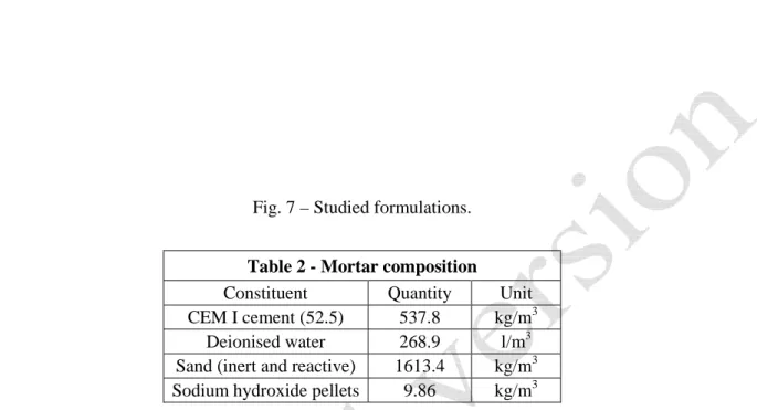
Fig. 7 – Studied formulations.
Table 2 - Mortar composition
Constituent Quantity Unit CEM I cement (52.5) 537.8 kg/m3 Deionised water 268.9 l/m3 Sand (inert and reactive) 1613.4 kg/m3 Sodium hydroxide pellets 9.86 kg/m3
Two series of specimens were made: non-reactive and reactive. The specimens were removed from their moulds after ten days at 20°C wrapped in plastic films in order to avoid desiccation. They were then kept at 60°C and 95% RH. Length and mass changes were measured and expansion induced by ASR was computed. The results (swelling vs. time) for the three previous formulations are shown in Fig. 8. The IVC1 formulation (including only fine reactive aggregates) has hardly any length change (swelling remains under 0.02% after 150 days) whereas the IVC3 formulation (including only coarse reactive aggregates) has a swelling of about 0.16% after 150 days. This fact can be explained by a difference of available porous volume according to reactive aggregate radius. This is contradictory with what has already been shown for opal aggregates [16][17]: the smaller the reactive aggregates, the more ASR expansion. This can be explained by the different reactive aggregates used (opal for Diamond and Thaulow [16] and Hobbs and Gutteridge [17] and siliceous limestone in our study).
Furthermore, when small and large reactive aggregates are combined in the same formulation, the swelling induced by ASR is reduced (expansion about 0.11% at 300 days, 25% less than IVC3 swelling). This is regardless of the volume of reactive silica, which has been doubled. An addition of fine reactive silica particles can reduce the swelling induced by ASR. This is relevant with what has already been shown in laboratory experiments for siliceous fillers [18], fly ash [20][21], silica fumes [21][22][23], rice husk [22][24][25], ground clay brick [26] or slag [27][28]. This reduction is due to alkalis consumption by the fine reactive aggregates. ASR gel is created around each small aggregate, the volume of precipitates remains smaller than available porous volume. This generates low expansion. The amount of alkalis available for large aggregates and gel volume is therefore significantly reduced. Corresponding ASR expansion is then reduced.
0.00% 0.02% 0.04% 0.06% 0.08% 0.10% 0.12% 0.14% 0.16% 0.18% 0 50 100 150 200 250 300 Time (days) A S R e x p a n s io n IV C3 IV C1C3 IV C1
Fig. 8 – Experimental ASR expansion for the three studied formulations.
4.2 Numerical simulations
Numerical simulations of these experiments have been carried out using the previous modeling. Needed parameters were fitted for the formulations IVC1 and IVC3 using experimental data (see Table 3). The diffusion coefficients control ASR kinetics and the coefficients g
i
k control the maximal expansion. The comparison between experimental and numerical expansions induced by ASR for the formulations IVC1 (only fine reactive aggregates) and IVC3 (only coarse reactive aggregates) is presented in Fig. 9.
Table 3 - Data used for the numerical simulations for the different formulations
Data IVC1 IVC3 IV C1C3 Unit
C1 C3 RREV 0.13 2.59 2.59 mm Ri 0.07 1.41 0.07 1.41 mm pSiO 5% 5% 5% 5% - a i n 1 1 7000 1 - ( )Na Dia 5 10 -13 5 10-10 5 10-13 5 10-10 dm²/s ( )Na Dihcp 5 10 -10 5 10-10 5 10-10 dm²/s ( )Ca Da i 5 10 -14 5 10-11 5 10-14 5 10-11 dm²/s ( )Ca Dhcp i 5 10 -11 5 10-11 5 10-11 dm²/s g i k 2.5 1011 1.3 107 2.5 1011 1.3 107 dm-4
A numerical simulation of the formulation IVC1C3 (combining fine and coarse reactive aggregates) was then carried out (see Fig. 10). The parameters used for this simulation were those fitted earlier for each formulation, only the number of reactive aggregates for the fine reactive aggregates was adjusted according to the reactive aggregate size grading (see Table 3: 7000 fine for 1 coarse reactive aggregate).
0.00% 0.04% 0.08% 0.12% 0.16% 0.20% 0 50 100 150 200 250 300 Time (days) A S R e x p a n s io n IV C3 - exp. IV C3 - fitting IV C1 - exp. IV C1 - fitting
Fig. 9 - Comparison between experimental and numerical ASR expansions for the formulations IVC1 and IVC3.
The reduction in ASR swelling induced by the addition of fine reactive aggregates is clearly reproduced (Fig. 10) since the predicted ASR expansion for the formulation IVC1C3 (combining fine and coarse reactive aggregates) is about 0.05% compared to 0.16% for the formulation IVC3 (with only coarse reactive aggregates). Nevertheless, there is a gap between predicted and measured expansion induced by ASR (0.05% for prediction versus 0.13% according to the experiments). The proposed modeling qualitatively explains the ASR swelling reduction effect thanks to competition phenomena around different sized reactive aggregates. Some assumptions are yet too simple (certainly the composition of the reaction products) to have a reliable ASR swelling prediction.
0.00% 0.02% 0.04% 0.06% 0.08% 0.10% 0.12% 0.14% 0.16% 0.18% 0 50 100 150 200 250 300 Time (days) A S R e x p a n s io n IV C1 IV C3 IV C1C3 – exp. IV C1C3 – sim. 0.00% 0.02% 0.04% 0.06% 0.08% 0.10% 0.12% 0.14% 0.16% 0.18% 0 50 100 150 200 250 300 Time (days) A S R e x p a n s io n IV C1 IV C3 IV C1C3 – exp. IV C1C3 – sim.
5. CONCLUSION
A new model for the prediction of the chemical evolution of concretes affected by ASR has been presented. It has been developed exclusively on the basis of the laboratory experimental results obtained with a crushed siliceous limestone. It aims at describing the influence of the reactive aggregate grading on ASR. It is based on the description of the simultaneous transport of alkalis and calcium ions towards different reactive aggregates within a Relative Elementary Volume (REV). The chemical equilibrium between alkalis, calcium ions and portlandite is taken into account. Local reaction mechanisms are described using very simple assumptions: immediate reactions (ASR kinetics is controlled by diffusion) and two different reaction products with fixed composition. Sink terms in the diffusion equations allow describing the concentration decrease induced by simultaneous consumption by different reactive aggregates.
The modeling allows evaluation of the evolution of all concentrations within the REV around each reactive aggregate (alkalis, calcium ions, reactive silica, portlandite and reaction products). It also allows evaluation of ASR kinetics and swelling of affected concretes. It has been used to simulate the results of a experimental laboratory programme including a crushed siliceous limestone. The ASR swelling reduction induced by an addition of fine reactive aggregates observed experimentally is clearly reproduced. Nevertheless, there remains a gap between predicted and experimental results.
In order to avoid this underestimation, a micro-mechanical modeling for the calculation of the swelling induced by ASR will be designed and the local reaction mechanisms will be modified; ASR reaction mechanisms will be added (including composition of the reaction products, liberation of the alkalis and substitution by calcium ions). This work will be published later.
ACKNOWLEDGEMENTS
The authors would like to thank the DER and CIH departments of Electricité de France (EdF) and especially Hélène Tournier-Cognon and Eric Bourdarot for their financial and scientific support.
REFERENCES
[1] Dent Glasser L. S. and Kataoka N. (1981), “The chemistry of alkali-aggregate reaction”, Cement and Concrete
Research 11(1), pp. 1-9.
[2] Poole A. B. (1992), “Alkali silica reactivity mechanisms of gel formation and expansion”, Proceedings of the 9th
International Conference on Alkali-Silica Reaction in concrete (ICAAR), London, England, pp. 782-789.
[3] Dron G., Brivot F. and Chaussadent D. (1997), “The mechanism of alkali-silica reaction”, Proceedings of the
10th International Congress of the Chemistry of Cement, 4iv074 - 8p, Göteborg, Sweden.
[4] Lombardi J., Perruchot A. and Massard P. (2000), “Experimental evaluation of composition and volume variability of Ca-Si gels, first products of alkali silica reaction (ASR)”, Proceedings of the 11th International Conference on Alkali-Aggregate Reaction in concrete (ICAAR), Québec City, Québec, pp. 81-87.
[5] “Recommandations pour la prévention des désordres dus à l’alcali-réaction” (1994), Presses du Laboratoire
Central des Ponts et Chaussées (in French), Paris, France.
[6] Mather B. (1999) “How to make concrete that will not suffer deleterious alkali-silica reaction”, Cement and
Concrete Research 29, pp. 1277-1280.
[7] Sellier A., Bournazel J.-P. and Mébarki A. (1995), “Une modélisation de l'alcali-réaction intégrant une description des phénomènes aléatoires locaux”, RILEM Materials and Structures 28 (in French), pp. 373-383. [8] Bažant Z. P. and Steffens A (2000), “Mathematical model for kinetics of alkali-silica reaction in concrete”,
Cement and Concrete Research 30, pp. 419-428.
[9] Furusawa Y, Ohga H. and Uomoto T. (1994), “An analytical study concerning prediction of concrete expansion due to alkali-silica reaction”, Proceedings of the 3rd International Conference on Durability of Concrete,
[10]Uomoto T., Furusawa Y. and Ohga H. (1992), “A simple kinetics based model for predicting alkali-silica reaction”, Proceedings of the 9th International Conference on Alkali-Aggregate Reaction in Concrete (ICAAR),
London, England, pp. 1077-1084.
[11]Xi Y., Suwito A., Wen X., Meyer C. and Jin W. (1999), “Testing and modelling alkali-silica reaction and the associated expansion of concrete”, Mechanics of quasi-brittle materials and structures, Ed. HERMES Science Publications, Paris, pp. 217-232.
[12]Poyet S. (2003), “Etude de la degradation des ouvrages en béton atteints par la réaction alcali-silice : approche expérimentale et modélisation numérique multi-échelles des dégradations dans un environnement hydro-chemo-mécanique variable”, PhD thesis of the University of Marne la Vallée (in French), France, 237p.
[13]Sellier A. and Capra B. (1997), “Modélisation physico-chimique de la reaction alcali-granulats : apport au calcul des structures dégradées”, Revue française de Génie Civil 1(3) (in French), pp. 445-481.
[14]Larive C., Laplaud A. and Coussy O. (2000), “The role of water in alkali-silica reaction”, Proceedings of the
11th International Conference on Alkali-silica Reaction in concrete, pp. 61-69, Québec City, Québec.
[15]Multon S., Merliot E., Joly M. and Toutlemonde F. (2004), “Water distribution in beams damaged by Alkali-Silica Reaction: global weighing and local gammadensitometry”, Materials and Structures 37(269), pp. 282-288.
[16]Diamond S. and Thaulow N. (1974), “Study of expansion due to ASR as conditioned by the grain size of the aggregate”, Cement and Concrete Research 4(4), pp. 591-607.
[17]Hobbs D. W. and Gutteridge W. A. (1979), “Particle size of aggregate and its influence upon the expansion caused by the alkali-silica reaction”, Magazine of Concrete Research 31(109), pp. 235-242.
[18]Guedon-Dubied J.-S., Cadoret G., Durieux V., Martineau F., Fasseu P. and Van Overbecke N. (2000), “Study of Tournai limestone in Antoing Cimescaut quarry, petrological, chemical and alkali-reactivity approach”,
Proceedings of the 11th International Conference on Alkali-Aggregate Reaction in concrete, Québec City,
Québec, pp. 335-344.
[19]Bleszinski R. F. and Thomas M. D. A. (1997), “Microstructural studies of alkali-silica reaction in fly ash concrete immersed in alkaline solutions”, Advanced Cement Based Materials 7, pp. 66-78.
[20]Shehata M. H. and Thomas M. D. A. (2000), “The effect of fly ash composition on the expansion of concrete due to alkali-silica reaction”, Cement and Concrete Research 30, pp. 1063-1072.
[21]Mu B. and Li Z. (2000), “Mechanical properties and microstructures of alkali-silica reacted concrete with fly ash, silica fume and calcium nitrite salt”, Concrete Science and Engineering 2, pp. 2-7.
[22]Hasparyk N. P., Monteiro P. J. M. and Carasek H. (2000), “Effect of silica fume and rice husk on alkali-silica reaction”, ACI Materials Journal 97, pp. 486-492.
[23]Gudmunsson G. and Olafsson H. (1999), “Alkali-silica reactions and silica fume, 20 years of experience in Iceland”, Cement and Concrete Research 29, pp. 1289-1297.
[24]Yu Q., Sawayama K., Sugita S., Shoya M. and Isojima Y. (1999), “The reaction between rice husk and Ca(OH)2
solution and the nature of its product”, Cement and Concrete Research 29, pp. 37-43.
[25]Jauberthie R., Rendell F., Tamba S.and Cisse I. (2000), “Origin of the pozzolanic effect of rice husks”,
Construction and Building Materials 14, pp. 419-423.
[26]Turanli L., Bektas F. and Monteiro P. J. M. (2003), “Use of ground clay brick as a pozzolanic material to reduce the alkali-silica reaction”, Cement and Concrete Research 33, pp. 1539-1542.
[27]Ramachandran V. S. (1998), “Alkali-aggregate expansion inhibiting admixtures”, Cement and Concrete
Composites 20, pp. 149-161.
[28]Lane D. S. and Ozyildirim C. (1999), “Preventive measures for alkali-silica reactions (binary and ternary systems)”, Cement and Concrete Research 29, pp. 1281-1288.
APPENDIX
α Function describing the equilibrium in solution between alkalis and calcium ions in presence of sufficient portlandite
d Isotropic and uniform damage within the Relative Elementary Volume
( )
XDai D
( )
X hcpi Homogenized diffusion coefficients for the ionic species X (calcium Ca and alkalis Na respectively) within and outside the reactive aggregate i respectively
asr
0
ε Data for ASR inelastic strain evolution
φi Volume fraction of the reactive aggregates of the granular class i
( )
X iΦ Flux of ions X penetrating all the reactive aggregates of the granular class i γX Davies activity coefficient for the ionic species X
I Ionic strength of the inner solution of concrete g
i
k Damage parameter for the reactive aggregates i
M Mass of the aggregates (reactive and inert) for 1 m3 of concrete a
i
n Number of reactive aggregates of the granular class i
( )
Ca iΠ Sink term in the diffusion equation for the reactive aggregate i describing the dissolution/precipitation of portlandite
pSiO Percentage of reactive silica within the reactive aggregates
Ri Mean radius of the reactive aggregates of the granular class i
RREV Radius of the Relative Elementary Volume
ρ Density of the aggregates (reactive and inert)
( )
XSireac S
( )
X hcpi Sink terms of the diffusion equation within and outside the reactive aggregate i respectively
a i
V Volume of the reactive aggregate of the granular class i p
i
V Porous volume surrounding the reactive aggregates i available for the swelling of the reaction products
gel mol
V Molar volume of the reaction products (gel and C-S-H)
VREV Volume of the Relative Elementary Volume
(X) Chemical activity of the ionic species X
i
X (Cai Nai) Homogenized concentration of the ionic species X (calcium Ca and alkalis Na respectively) around the reactive aggregate i