HAL Id: hal-01761671
https://hal.archives-ouvertes.fr/hal-01761671
Submitted on 9 Apr 2018HAL is a multi-disciplinary open access archive for the deposit and dissemination of sci-entific research documents, whether they are pub-lished or not. The documents may come from teaching and research institutions in France or abroad, or from public or private research centers.
L’archive ouverte pluridisciplinaire HAL, est destinée au dépôt et à la diffusion de documents scientifiques de niveau recherche, publiés ou non, émanant des établissements d’enseignement et de recherche français ou étrangers, des laboratoires publics ou privés.
CoNiCrAlY/Talc cermet prepared by Spark Plasma
Sintering
Nicolas Ratel-Ramond, D. Monceau, C. Estournes, D. Oquab
To cite this version:
Nicolas Ratel-Ramond, D. Monceau, C. Estournes, D. Oquab. Reactivity and microstructure evolution of a CoNiCrAlY/Talc cermet prepared by Spark Plasma Sintering. Surface and Coatings Technology, Elsevier, 2010, 205 (5), pp.1183-1188. �10.1016/j.surfcoat.2010.08.091�. �hal-01761671�
Reactivity and microstructure evolution of a CoNiCrAlY/Talc cermet prepared by spark plasma sintering
N. Ratel, D. Monceau, C. Estourn`es, D. Oquab
PII: S0257-8972(10)00740-1
DOI: doi:10.1016/j.surfcoat.2010.08.091
Reference: SCT 16060
To appear in: Surface & Coatings Technology
Received date: 9 February 2010 Accepted date: 19 August 2010
Please cite this article as: N. Ratel, D. Monceau, C. Estourn`es, D. Oquab, Reactivity and microstructure evolution of a CoNiCrAlY/Talc cermet prepared by spark plasma sintering, Surface & Coatings Technology (2010), doi: 10.1016/j.surfcoat.2010.08.091
This is a PDF file of an unedited manuscript that has been accepted for publication. As a service to our customers we are providing this early version of the manuscript. The manuscript will undergo copyediting, typesetting, and review of the resulting proof before it is published in its final form. Please note that during the production process errors may be discovered which could affect the content, and all legal disclaimers that apply to the journal pertain.
ACCEPTED MANUSCRIPT
Reactivity and microstructure evolution of a CoNiCrAlY/Talc cermet
prepared by spark plasma sintering
N. Ratel 1, +, D. Monceau 1, C. Estournès 2, D. Oquab 1, *
1 Institut Carnot CIRIMAT ENSIACET 4, allé Emile Monso, BP 44632 31432 Toulouse cedex 4, France
2 CNRS, Institut Carnot CIRIMAT, F-31062 Toulouse Cedex 9, France
+ Present adress : CEMES 29, rue Jeanne Marvig, BP 94347, 31055 Toulouse Cedex 4 , France * Corresponding author : [email protected]
Abstract
A mixture of CoNiCrAlY and talc powders is considered as a new candidate composition for abradable seal coatings applications. Dense specimen having the composition of 1:20 weight ratio of talc with respect to CoNiCrAlY were prepared using the Spark Plasma Sintering (SPS) technique. The aim of the present article is to investigate the reactivity and microstructure evolution of the β/γ-CoNiCrAlY based cermet. The resulting microstructures were analysed and their compositions determined using standard analytical techniques such as SEM, TEM and X-Ray diffraction. After fabrication, the bulk of the material is shown to contain a continuous oxide layer of MgAl2O4 at the periphery of metallic particles, resulting from the reaction between aluminium, which has diffused from the bulk of CoNiCrAlY grains, with magnesium and oxygen delivered during the high temperature decomposition of the talc phase. Thermodynamic calculations results are found to be consistent with the experimental observations. The oxidation behaviour at high temperature of this cermet was also investigated. It was shown that at its external suface a continuous double layer is formed – one external film at the suface of the sample made of MgAl2O4 and the second one more internal in between the later and the cermet made of α-Al2O3. The oxide scale is protective
ACCEPTED MANUSCRIPT
with low oxidation kinetics typical of alpha alumina growth (k = 1.8⋅10−7mg2⋅cm−4⋅s−1
P at
1050°C in flowing dry air)..
Keywords: abradable seals, talc, MCrAlY, Spark Plasma Sintering, SPS, high temperature coatings, oxidation
Introduction
Abradables seal coatings are currently used in gas turbine engines in order to reduce the gap between rotating and stationary parts, thus ensuring that more gas is drawn through the blade area and less escapes over the tips of the blades [1]. In this way, the overall efficiency of the engine is improved. The function of these materials is to wear preferentially when rotating turbine blades come into contact, thus ensuring a minimum clearance between the blade and the stationary part. In turbine application, these materials are submitted to high temperature (up to around 1500°C) in a corrosive atmosphere and subjected to erosive wear. Abradable materials are thus challenging materials, since they must show a good corrosion and erosion resistance, as well as they must be soft enough to wear preferentially with respect to the blade.
The composition of abradable materials strongly depends on the temperature domain of its application. In the low temperature domain (below 500°C), polymers and aluminium polymers are used. When increasing the temperature up to 1100°C, MCrAlY materials are used, into which a solid lubricant is added. The role of the metallic matrix is to give to the material its mechanical strength, combined with oxidation and corrosion resistance. The solid lubricant is inserted in order to facilitate the shear process, and to reduce the size of the
ACCEPTED MANUSCRIPT
particles produced during the blade incursion into the abradable material [2]. The size of these particles is an important factor, regarding subsequent erosion phenomena.
Abradable seal coatings are usually manufactured using thermal spray techniques [3]. The abradable powder is rapidly heated and projected at high velocity onto the substrate, where it is deposited under the form of molten particle splats. After successive passes of the spray gun, a layered structure is obtained. Thermal spray powders are usually constituted with a mixture of MCrAlY alloys or ceramic, combined with a solid lubricant, such as hexagonal boron nitride (h-BN), CaF2 or bentonite and clay minerals. Instead of thermal spray techniques, the Spark Plasma Sintering (SPS) technique is used in the present work.
The Spark Plasma Sintering (SPS) technique is an emergent fabrication process for new materials [4]. With this technique, sintering is achieved through specimen heating by the passage of a pulsed DC electric current into the graphite die and within the specimen itself placed inside the die when it is conducting. The temperature at which a material is sintered is reduced by the application of an uniaxial compressive pressure. The sintering process occurs under an atmosphere where the partial pressure of oxygen is very low, in order to avoid oxidation phenomena. Although the exact mechanisms involved in SPS are not yet clearly identified, the sintering process occurs within very short times [4]. Past investigations have shown the efficiency of this technique in various fields, such as ceramic and composite materials [5-9], metallic glasses [10] etc. Recently, the fabrication of high temperature materials, such as MCrAlY coatings on single crystal nickel superalloy substrates, was performed using the SPS technique [11, 12]. These works have shown the feasibility of dense metallic coatings in short times when compared to conventional techniques, with a good control of the coating composition. In addition, the SPS process allows the assembly of
multi-ACCEPTED MANUSCRIPT
layers materials, as shown by the fabrication of complete thermal barrier coating systems using the SPS process [13].
In the present investigation, a cermet based on a CoNiCrAlY metal alloy and containing a controlled amount of talc is prepared using the SPS technique. MCrAlY alloys are currently used as coatings or as bond coats for thermal barrier coatings systems on nickel superalloys, for their good oxidation and corrosion properties [14]. Talc is a mineral constituted of hydrated magnesium silicates. Its chemical formula is Mg3Si4O10(OH)2. As mentioned before, talc is used for its lubricant properties. The aim of the present investigation is to analyse the chemical stability of talc and CoNiCrAlY mixture, during the SPS fabrication of the cermet.
Materials and Methods
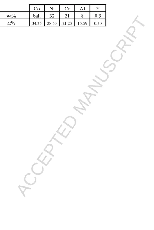
The metallic powder alloy chosen for the present investigation is the CoNiCrAlY alloy, such as the commercial powder AMDRY® 995 (Sulzer Metco). The composition of the powder is given in Table 1, with an average particle size around 35µm.. This powder is mixed with talc powder particles, whose average particle size is around 1.8µm. The two powders were mixed in the proportion of 1:20 weight ratio of talc. During the mixture of the powders, the fine talc particles cover the larger metallic particle surfaces.
The obtained mixture is placed inside a graphite die (15mm inner diameter) and between two alumina layers, so that the electric current goes mainly through the graphite die during the SPS process. The powder is thus heated by conduction with boron nitride coated papyexTM sheets (graphite sheet), between which the mixture (talc + MCrAlY) powder is placed, to prevent the diffusion of the carbon contained in the papyex towards the MCrAlY particles [13]. In this way, the formation of carbide phases can be avoided. The material was then
ACCEPTED MANUSCRIPT
sintered using a Dr. Sinter 2080 apparatus available at the Plateforme Nationale de Frittage Flash du CNRS at Toulouse, previously described in [12]. The samples were sintered at 1000°C, under a pressure of 100MPa with a dwell time of 10 minutes.
Chemical interaction of the components
The microstructure of CoNiCrAlY/talc and CoNiCrAlY specimens obtained after fabrication in identical conditions are shown in Figure 1. The materials obtained are dense and uniform in terms of microstructure. In both cases, the metallic particles are shown to have a β/γ structure, and the grain size of the metallic particles does not seem to be modified during the SPS process. In the case of a CoNiCrAlY-talc mixture, a thin film of talc is deposited on the surface of each metallic particle during the mixture of the powder. After fabrication, the metallic particles are surrounded by a dark compound which contains the elements Mg, Si and O of the talc initially introduced in the powder mixture.
EDS maps performed on the bulk section of a specimen in a scanning electron microscope confirm the presence of the constitutive elements of talc, namely Mg, Si, and O around the metallic particles. They are shown in Figure 2. Moreover, a high concentration in Al is observed at the periphery of each metallic particle. This point can be correlated to the absence of β-NiAl phase at the vicinity of the metal/talc interfaces. Both phenomena indicate a chemical interaction between the aluminium contained in the metal phases and the constitutive elements of talc.
Figure 3 shows TEM observations performed on a specimen cut from the bulk of the material obtained after SPS fabrication. The presence of a thin layer (around 150 nm thickness) constituted of small crystallites is observed at the surface of the metallic particles. EDS
ACCEPTED MANUSCRIPT
analyses performed on these crystals show that this phase is rich in Mg, Al and O. Selective Area Diffraction (SAD) patterns corresponding to these crystallites show that the phase surrounding the metallic particles is the MgAl2O4 spinel phase (see Figure 3). The formation of this oxide phase should result from the reaction of aluminium coming from the alloy with the magnesium contained in the talc and the oxygen contained in the water vapour delivered during talc decomposition at high temperature. Indeed, it is well known that talc dehydrates at temperatures above 800°C [15]. Above this temperature, the talc molecule loses its hydroxyls groups and delivers water vapor. This lost results in the decomposition of pure talc into enstatite MgSiO and cristobalite 3 SiO minerals [15, 16]. This reaction occurred during the 2 high temperature sintering process. In addition, small spherical particles, visible in Figure 3, are observed within the sheet structure observed between the metallic particles. EDS analyses performed on these particles have revealed a composition of around 50at% silicon in solution within a mixture of cobalt, nickel and chromium. The silicon enrichment of the γ metallic phases was also observed by EDS analysis. The products of the high temperature decomposition of talc have reacted with the metallic elements during the sample preparation by SPS. These reactions result in the formation of a spinel oxide MgAl2O4 and silicon enrichment of the metallic phases.
Thermodynamic calculations were conducted using HSC Chemistry ® software [17]. The aim of these calculations was the determination of the compounds which could form at the thermodynamic equilibrium in a closed system consisting of a given quantity of talc mixed with cobalt, nickel, chromium, aluminium and yttrium (CoNiCrAlY) according to the experimental composition. The hydrogen contained in the talc was excluded from the calculations. It is assumed that after high temperature decomposition of the talc, the hydrogen migrates outside the considered system as fast diffusing species. The mixture of these elements is assumed to be homogeneous. A list of all the compounds that might form from the
ACCEPTED MANUSCRIPT
initial composition is then given. Depending on the chemical activity of each species, and the Gibbs energies of reactions contained in the database, the software allows the computation through energy minimization of the fraction of each compound obtained at the thermodynamic equilibrium. Figure 4 shows the evolution of the equilibrium composition calculated as a function of the temperature of the system. At the thermodynamic equilibrium, the composition at 1000°C shows a high content in nickel, cobalt and chromium, which corresponds to the γ phase observed in the specimen. In agreement with the observations, the presence of the β-NiAl phase is also predicted. The minor phases predicted by the calculations consist in oxide phases, such as the MgAl2O4 spinel and several silicides (CoSi, CrSi, NiSi). These silicides can be correlated with the presence of the nearly spherical particles showing a high content of silicon, cobalt, chromium and nickel that were observed by TEM, and with the enrichment in silicon of the metallic phases. Another feature experimentally observed and correctly predicted by the calculation is the formation of a small amount of alumina at temperatures above 900°C. The formation of an oxide scale constituted of alumina and MgAl2O4 spinel within the material is thus correctly predicted by the thermodynamic calculations at equilibrium. This point is in agreement with the experimental observations shown in Figure 3. In addition, the calculations predict the presence of β-NiAl, and of silicides, which are observed in the bulk of the material. The thermodynamic analysis shows good agreement with experimental observations.
Oxidation Behaviour
The isothermal oxidation behaviour of the external surface of the CoNiCrAlY based cermet was investigated using thermal analysis. A specimen fabricated by SPS from a CoNiCrAlY-talc mixture was mechanically polished down to 1µm. The surface was cleaned using acetone, ethanol and ultrasonic technique. The specimen was then mounted inside a Setaram TAG 24s
ACCEPTED MANUSCRIPT
thermal analyser. The specimen was then annealed at 1050°C for 100 hours under a flow of synthetic air. The previously described internal reaction between the talc and the metallic alloy leads to negligible mass variation since only hydrogen is lost during the process. Then, the mass gain observed during the annealing was associated with the growth of an external oxide scale. Figure 5 shows the parabolic evolution of the mass gain per unit area (∆m/S ) with annealing time. The parabolic oxidation constant during the stationary regime was calculated to be k = 1.8⋅10−7mg2⋅cm−4⋅s−1
P using the complete parabolic kinetics law t= A +
B (∆m/S) + (1/kp).(∆m/S)² [18]. This value is typical of alumina forming materials and is close to the value found for CoNiCrAlY coatings [19]. The addition of talc does not degrade the oxidation resistance of the CoNiCrAlY material.
The oxide scale created during the thermal analysis experiment was then examined using X-ray diffraction in low incidence mode (3°). The wavelength used corresponds to K-α1 of a Cu anode. The depth of material analyzed corresponds to a few micrometers. Figure 6 shows the X-ray diffraction pattern obtained on this oxidized surface. The indexation of this pattern shows the presence of α-Al2O3 and MgAl2O4 oxides. TEM observations combined with EDS analyses were performed to complete these results. The latter show that the superficial oxide scale is constituted by two layers. The external layer is the MgAl2O4 phase, while the internal layer is made of α-Al2O3. In presence of air, and considering that the chemical activity of metallic elements is equal to 1, thermodynamic data show that MgAl2O4 oxide is more stable than α-Al2O3 and MgO. However, the formation of this oxide leads to a local decrease in Mg concentration. In these conditions, α-Al2O3 might become the most stable oxide in contact with the Mg depleted metallic alloy and then α-Al2O3forms beneath the MgAl2O4 layer. The analysis of the oxide growth kinetic is consistent with the experimental observations, with the formation of an alumina layer on top of which a layer of MgAl2O4 is observed. The oxide scale is shown to be continuous and protective and acts as a diffusion barrier. This protective
ACCEPTED MANUSCRIPT
external oxide layer prevents oxygen to diffuse to the sample core through the sheet oxide microstructure which was formed between the CoNiCrAlY particles during fabrication by SPS.
Conclusion
In the present study, it is shown that Spark Plasma Sintering is an efficient technique to prepare a multi material cermet from a CoNiCrAlY-talc mixture. The material fabricated from a mixture of powders consists in the assembling of spherical metallic particles surrounded by fine talc sheets. During the SPS process, a reaction between the CoNiCrAlY and the talc powders has been observed. This reaction results in the formation of a thin oxide layer of MgAl2O4 at the periphery of all the metallic particles. This reaction is accompanied by the diffusion of Si into the CoNiCrAlY grains leading to a Si enrichment of the γ phase.. Alumina is also formed locally between the MgAl2O4 scale and CoNiCrAlY. Assuming that hydrogen produced from the talc decomposition can migrate freely out of the sample, thermodynamic calculations show good agreement with experimental observations. The investigation of isothermal oxidation behaviour shows that the addition of talc does not affect the oxidation kinetics. The CoNiCrAlY-talc based cermet behaves like a bulk alumina former material.
Acknowledgements
The authors are grateful to the French Délegation Générale pour l’Armement, Turbomeca (Safran Group) and SNECMA (Safran Group) for funding of the research project (DGA grant n° 08.60.017.00.470.75.01). M.C. Lafont (CIRIMAT) is deeply acknowledged for sample preparation and the TEM observations of the specimen.
ACCEPTED MANUSCRIPT
References
[1] S. Li, C. Langlade-Bomba, D. Treheux, J. Phys. IV France, 10 (2000), 113-118
[2] F. Ghasripoor, R. Shmid, M. Dorfman, Mat. World, Vol.5, No. 6 (1997), 328 [3] M.A. Clegg, M.H. Mehta, Surf. & Coat. Tech., 34 (1988) 69-77
[4] R. Orru, R. Licheri, A. M. Locci, A. Cincotti, G. Cao, Mat. Sci. and Eng. R 63 (2009) 127–287
[5] M. Nygren (M.), Z. Shen,. Solid State Science, 5, (2003) 125
[6] R. Chaim, M. Levin, A. Shlayer and C. Estournes, Adv. in Applied Ceramics 107(3) (2008) 159-169.
[7] A. Chesnaud, C. Bogicevic, F. Karolak, C. Estournès, G. Dezanneau, Chem. Commun., (2007), 1550-1552.
[8] P. Dibandjo, L. Bois, C. Estournes, B. Durand, P. Miele, Microporous and Mesoporous Materials 111 (2008) 643–648,
[9] C. Elissalde, C. Estournès and M. Maglione, J. Am. Ceram. Soc., 90 (3), (2007) 973-976. [10] G. Xie, W. Zhang, D. V. Louzguine-Luzgin, H. Kimura, A. Inoue, Scripta Mat., 55, (2006), 687-690
[11] D. Oquab, C. Estournes, D. Monceau, Adv. Eng. Materials, 9, 5 (2007) 413-417.
[12] D. Oquab, D. Monceau, Y. Thebault and C. Estournes, Mat. Science Forum Vols. 595-598 (2008) 143-150
[13] D. Monceau, D. Oquab, C. Estournes, M. Boidot, S. Selezneff, Y. Thebault, Y. Cadoret, Surf. & Coat. Tech., 204 (2009) 771–778
ACCEPTED MANUSCRIPT
[15] H. De Souza Santos, K. Yada, Clays and Clay Minerals, Vol. 36, No. 4, (1988) 289-297 [16] M. Zhang, Q. Hui, X.J. Lou, S.A.T. Redfern, A.K.H. Salje, S.C. Tarantino, American Mineralogist, Volume 91, (2006) 816-825
[17] http://www.outotec.com/pages/Page.aspx?id=21783&epslanguage=EN
[18] D. Monceau, B. Pieraggi, Oxidation of Metals, Vol. 50, Nos. 5/6, (1998) 477-493
ACCEPTED MANUSCRIPT
Table 1: Composition of the CoNiCrAlY (AMDRY® 995) powder used in this investigation
Co Ni Cr Al Y
wt% bal. 32 21 8 0.5
ACCEPTED MANUSCRIPT
Captions
Figure 1: Microstructure observed by optical microscopy in the bulk of the material after fabrication: a) CoNiCrAlY/talc cermet
b) CoNiCrAlY alloy sintered in the same conditions. CoNiCrAlY particles exhibit a β/γ structure in both cases.
Figure 2: Qualitative EDS map of the material presented in Figure 1. Note the strong aluminium concentration at the metal/talc interface.
Figure 3: TEM observations: left: View of the observed area, and right: TEM observation of the metal/talc interface and SAD patterns of MgAl2O4 oxide phase surrounding the metallic particles. Note the layer of crystallites surrounding the metallic particles.
Figure 4: Evolution of the equilibrium composition with temperature as calculated by HSC Chemistry ® software.
Figure 5: Evolution of the mass gain associated to the creation of the external oxide layer during 100h annealing at 1050°C in flowing synthetic air.
Figure 6: Diffraction pattern produced by the oxide layer obtained on a specimen annealed for 100 hours at 1050°C. The presence of Al2O3 and MgAl2O4 phases is clearly visible.
Figure 7: TEM observations of the oxide layer formed inside the specimen during 100 hours of annealing at 1050°C: left View of the specimen, right: SAD patterns of α-Al2O3 oxide layer below the MgAl2O4 layer