DOCTORAT DE L'UNIVERSITÉ DE TOULOUSE
Délivré par :
Institut National Polytechnique de Toulouse (INP Toulouse)
Discipline ou spécialité :
Génie des Procédés et de l'Environnement
Présentée et soutenue par :
M. NICHOLAS RICHARD LIPPIATT
le mercredi 2 avril 2014
Titre :
Unité de recherche :
Ecole doctorale :
ETUDES SUR LA TEXTURE DU BETON POUR LE DEVELOPPEMENT
D'UN PROCESSUS DE RECYCLAGE DU BETON EN UTILISANT UN
CHAUFFAGE PAR MICRO-ONDES
Mécanique, Energétique, Génie civil, Procédés (MEGeP)
Laboratoire de Génie Chimique (L.G.C.)
Directeur(s) de Thèse :
M. FLORENT BOURGEOIS
Rapporteurs :
M. ERIC GARCIA-DIAZ, ECOLE DES MINES D'ALES Mme ANETTE MÜLLER, IAB Institut für Angewandte Bauforschung
Membre(s) du jury :
1 M. MARTIN CYR, INSA TOULOUSE, Président
i The author wishes to thank the French Research Agency ANR for their financial support through the COFRAGE project (ANR-Ecotech 2009), as well as all the partners of the project (Picheta, Colas, CNRS - IMS and Selfrag AG). He also wishes to thank a number of staff from the Laboratoire de Génie Chimique without whom this work would not have seen the day of light, in particular:
Emmanuel Cid, Senior Research Scientist with the Laboratoire de Génie Chimique, for his valuable contribution to the image analysis of the fracture patterns
Alain Muller and Jacques Labadie for designing and commissioning the Hopkinson bar test apparatus used in this work
Gwénaëlle Raimbeaux for demonstrating how to perform mercury porosimetry tests and for her help with helium pycnometry
Marie-Line de Solan-Bethmale for training in scanning electron microscopy
Christine Rey Rouch and Benjamin Bonfils for their assistance with thermogravimetric analysis
Alexandre Freulon for his help with cutting, polishing and other sample preparation techniques
Christophe Tenailleau and his team from the Centre Inter-universitaire de Recherche et d’Ingénierie des Matériaux for their help with X-ray tomography
Cedric Charvillat for his assistance with X-ray diffraction
Claudine Lorenzon for her constant and patient help with acquiring products for the laboratory Lahcen Farhi for his assistance preparing the laboratory and help with equipment failures Alain Philip for patience and assistance
Some friends must be mentioned as without them the quality of the author’s French would be even worse than it is and Toulouse would not have been the joy that it was; Marc, Ben, Vincent, Martial, Sarah, Meredith, Thibaut, Giannaras, Jean-Baptiste, Youen and Elodie.
Particular thanks must go to thesis supervisor Florent Bourgeois who made possible this amazing opportunity. Florent not only created and offered this project but personally assisted with a wide range of issues. The collaboration has been both productive and a pleasure. Once again, thank you.
ii
This thesis is concerned with the development of efficient concrete recycling technology. Concrete is the most used manufactured material on the planet and as a consequence uses more natural resources than any other industry. The industry is also responsible for 7% of the world’s carbon dioxide production, 50% of that originating from the decarbonisation of limestone. Given the magnitude of materials used and the waste produced the recycling of concrete would be a major environmental boon and should be made a priority.
The main obstacle to the development and implementation of a concrete recycling process is the necessity of separating concrete components, aggregate and cement paste before recycling. Microwave heating stands as an ideal candidate due to its capacity to selectively heat different phases in a multiphase material, thus producing phase boundary fracture and increasing the liberation of the component phases. The effects of microwave heating on concrete samples were investigated with the intent of concluding on the possibility of deriving a microwave-based recycling process for concrete. The effects were measured using standard macroscopic techniques and found a strong correlation between heating, increased porosity and decreased mechanical strength for concrete. In order to better understand the changes measured at the macroscopic scale, a dedicated image analysis technique was developed using electron microscopy to investigate local microscopic changes in concrete texture. Local investigation of the changes of heat treated concrete identified the presence of fracture porosity, which has significant explanatory power for observed changes in concrete properties most relevant to recycling.
Textural analysis of concrete subjected to microwave heating showed the growth of two distinct fracture networks throughout the cement paste matrix, whose development is associated with the microwave settings. These textural fracture properties correspond directly to the observed changes in mechanical properties as well as the observed liberation of aggregate particles.
Textural analysis shows that phase boundary fracture growth occurs rapidly in the early stages of microwave treatment and that the absolute value of textural liberation is significantly higher than that of physical liberation. This highlights the importance of choosing an appropriate comminution method to make efficient use of phase boundary fracture.
iii changes in properties of concrete most relevant to recycling, revealing the possibility of designing a concrete waste beneficiation process through manipulating concrete texture.
Since microwave heating was found to be able to manipulate the form taken by the fracture porosity, this work concludes that microwave heating of concrete is a promising technology for designing a concrete recycling scheme.
Moreover, through demonstration of causal links between textural properties and processing performance criteria, this work opens the possibility of an alternative approach for analysing and designing comminution process for minerals.
iv
L’objet de cette thèse porte sur le développement de technologies efficaces pour le recyclage du béton. Le béton est le plus utilisé des matériaux conçus par l’homme, et par voie de conséquence, sa fabrication consomme plus de ressources naturelles que n’importe quelle autre industrie. Le béton est responsable de 7% des émissions anthropiques de CO2, la moitié provenant de la décarbonatation du
calcaire. Compte-tenu des quantités de matières utilisées et de déchets produits, le recyclage du béton est un enjeu environnemental majeur, et une priorité grandissante.
Le principal défi au développement et à la mise en œuvre d’un procédé de recyclage du béton concerne la difficulté à séparer ses constituants, les graviers et la pâte de ciment. Le chauffage microonde est un candidat idéal pour parvenir à ce résultat, de par sa capacité à chauffer sélectivement les différentes phases d’un matériau multiphasique, induisant ainsi des fractures aux interfaces entre phases et conduisant à leur libération. Les effets du chauffage microonde sur le béton ont donc été étudiés dans cette thèse avec l’objectif de conclure quant au bien-fondé de développer un procédé de recyclage qui intègre les microondes. Les effets ont été mesurés par des analyses classiques d’échelle macroscopique qui ont mis en évidence une corrélation significative entre le chauffage, l’augmentation de porosité et la diminution des propriétés mécaniques du béton. Pour mieux comprendre les changements mesurés à une échelle macroscopique, une technique d’analyse locale d’images de la texture du béton, basée sur la microscopie électronique, a été développée.
L’analyse locale des changements induits par le chauffage du béton a révélé la présence d’une porosité de fractures, qui a permis d’expliquer les changements observés des propriétés du béton les plus pertinentes vis-à-vis du recyclage.
L’analyse de la texture du béton soumis au chauffage par microondes a mis en évidence la formation de deux réseaux de fractures dans la pâte de ciment, dont le développement est dicté par les conditions du chauffage microonde. Les propriétés texturales de ces réseaux de fractures ont été corrélées directement aux variations des propriétés macroscopiques du béton, ainsi qu’à la libération des agrégats.
L’analyse texturale a montré que la croissance de la fracture à l’interface entre les agrégats et la pâte de ciment survient durant les premiers instants du chauffage, et que la libération des agrégats dans le béton, appelée libération texturale, est significativement plus grande que la libération physique
v mode de fragmentation capable de tirer parti de la fracture sélective des interfaces agrégat-ciment. De plus, le travail réalise a établi qu’il existe des relations de causalité entre les variations de la porosité de fractures présente dans le béton et les propriétés du béton les plus significatives pour son recyclage, révélant ainsi la possibilité de concevoir un procédé de valorisation des déchets de béton en manipulant la texture du béton.
En établissant que le chauffage microonde permet de modifier la porosité de fractures du béton, ce travail conclut que le chauffage du béton par microondes est une technologie prometteuse pour concevoir un procédé de recyclage du béton.
Au-delà du seul objectif du recyclage du béton, la démonstration de l’existence de relations de causalité entre les propriétés de texture du béton et les critères de performance associés à sa fragmentation ouvre des perspectives nouvelles pour analyser et concevoir des procédés de broyage des minerais.
C
ONTENTS
List of Figures ... viii
List of Tables ...xiv
1 Introduction ...1
1.1 Concrete manufacturing and uses: significance and impacts ...2
1.2 Concrete waste beneficiation: stakes and challenges ...3
1.3 Bibliography for Chapter 1 ...5
2 State of the art ...9
2.1 The nature of concrete ...9
2.1.1 Cement ... 11
2.1.2 Aggregate ... 14
2.1.3 Concrete components and their consequences for processing ... 15
2.2 The nature of microwaves and microwave heating ... 21
2.2.1 Microwaves ... 23
2.2.2 Microwaves and solid matter ... 27
2.2.3 Microwaves and multiphase materials ... 30
2.2.4 Microwaves and concrete ... 32
2.3 Terms of reference for this work ... 37
2.4 Bibliography for Chapter 2 ... 39
3 Materials and methods ... 47
3.1 Concrete sample preparation ... 47
3.2 Thermal treatment... 51 3.2.1 Microwave heating ... 51 3.2.2 Oven heating ... 54 3.3 Concrete characterisation ... 55 3.3.1 Macroscopic measures ... 55 3.3.2 Microscopic analysis ... 72
vii
4 Validating the value of microwaves in concrete recycling ... 91
4.1 Investigation of microwave-assisted concrete recycling using single-particle testing ... 92
4.2 Notes and explanations ... 104
4.3 Bibliography for Chapter 4 ... 107
5 The effect of heat on concrete texture ... 111
5.1 Development of image analysis scheme and the concept of fracture porosity ... 111
5.2 Measurement of fracture porosity by SEM ... 112
5.2.1 Primary and secondary fracture networks ... 113
5.2.2 Textural vs physical liberation ... 116
5.2.3 Recycling-oriented investigation of local porosity changes in microwave heated concrete ... 126
5.3 Correlation between fracture porosity and relevant macroscopic concrete properties ... 145
5.3.1 Correlation between fracture porosity and fracture energy ... 145
5.3.2 Introducing the concept of mechanical texture for comminution process modelling and design ... 146
5.3.3 Correlation between fracture porosity and liberation ... 165
5.4 Implications for concrete recycling ... 167
5.5 Bibliography for Chapter 5 ... 173
6 Conclusions and perspectives ... 175
A Appendices... 181
A Size distribution and liberation ... 182
B Texture and porosity ... 190
C Mechanical testing ... 194
D Thermogravimetric analysis ... 197
E Mercury intrusion porosimetry ... 198
F Microwave heating data... 199
G Image analysis code ... 200
viii
Figure 1.1 Percentage of total aggregate used to make concrete composed of recycled aggregate showing less than 20% of concrete aggregate in most European countries is of recycled origin
2
Figure 1.2 Percentage of total construction and demolition waste recycled the low levels of recycling performed in most countries implies high levels of waste
4
Figure 2.1 Cross section of low porosity concrete 10 Figure 2.2 Fractal illustration of CSH gel, showing how an agglomeration of globules (white)
can repeat to form a structure with a lower packing density than the agglomeration alone and that this repetition creates a range of pore sizes
12
Figure 2.3 Schematic of concrete illustrating complexity and scale with (a) Schematic description of concrete structure and (b) volumetric proportions of concrete components
12
Figure 2.4 Schematic illustrating the heterogeneity in the cement phase of concrete near aggregate particles.
13
Figure 2.5 Concrete cross section showing what is considered the limits of the ITZ, 20-50μm. Lower grey level in the cement between the surface of the large aggregate particle and 20μm away indicates elevated levels of porosity
16
Figure 2.6 Schematic showing complex structure of calcium silicate hydrates and the different types and sizes of porosity that form because of this
18
Figure 2.7 Electromagnetic Spectrum showing the relative energy and frequency of microwaves compared to other electromagnetic radiation and their dominant interaction mechanisms with matter
22
Figure 2.8 Propagating transverse electromagnetic field showing perpendicular relationship of direction of travel, electric and magnetic fields
23
Figure 2.9 Illustration of dipole polarization by comparing molecules under no applied electric field, left and molecules under a constant electric field, right
24
Figure 2.10 Dielectric constant for polycrystalline Al2O3 illustrating the temperature and
frequency dependence of dielectric properties
25
Figure 2.11 Illustration of the variation in intermolecular forces between surface and bulk molecules. Fewer nearest neighbours creates unbalanced charged at the surface
27
Figure 2.12 Illustration of the frequency dependence of loss factor and permittivity 29 Figure 2.13 Numerical simulation of crack growth in mineral ore composed of dielectric
embedded in non-dielectric matrix exposed to high power microwaves showing fracture growth at phase interfaces and connecting embedded particles
ix
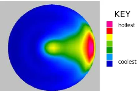
Figure 2.14 Simulated horizontal power density map, 50mm sphere showing hot spot below the samples surface
32
Figure 2.15 Losses in heterogeneous materials containing water without (a) and with (b) interfaces illustrating the different frequencies at which different types of water have the highest dielectric loss
33
Figure 2.16 Diagram of a near field wave applicator for creating controlled spalling in concrete 34 Figure 2.17 Diagram illustrating the loss of compressive strength in concrete when different
fractions of aggregate are replaced with recycled aggregates
35
Figure 3.1 Cubic concrete samples from ANR-COFRAGE 47 Figure 3.2 Cross section of untreated concrete S1, S3 and S5 49 Figure 3.3 Disassembled mould 49 Figure 3.4 MT-4 diamond blade saw 49 Figure 3.5 Experimental protocol from sample preparation to product characterisation 50 Figure 3.6 Single mode cavity capable of producing 2.45 GHz microwaves at power up to 2
kW
51
Figure 3.7 Typical absorption curve for microwave exposed concrete showing initial water related absorption peak and final plasma related absorption peak
52
Figure 3.8 Long microwave treated cubic sample showing colour changes indicative of elevated temperatures; red (300°C) and white (600°C) as well as black melting/ burning
53
Figure 3.9 Hopkinson bar 56 Figure 3.10 Calibration impact signal using 40mm bar, 60mm striker, 10mm drop showing a
near perfect match of measured and predicted signals. Measured signal was made using the calculated bridge factor
58
Figure 3.11 Impact signal for untreated cubic sample struck by 40mm striker from a height of 100mm showing the point of fracture
59
Figure 3.12 HPB impact signal for untreated S2 concrete sample showing recurring impact signal abnormalities
60
Figure 3.13 Impact signal for steel cylinder showing perturbations in the signal. Curve flattens as voltage exceeded hardware specifications
61
Figure 3.14 Impact signals from aluminium and PVC cylinders showing evidence of the internal reflection of compression waves
62
Figure 3.15 Speed of sound measured in cylinders of PVC and aluminium relative to the wave multiple used and using different impact energies. This shows how speed of sound measured in this way varies with the impact energy and how the apparent speed of sound increases with each internal reflection
x
signal perturbations are relative to the stiffness of materials tested showing decreasing stiffness with heat treatment as would be expected. All values shown relative to the highest stiffness value measured
Figure 3.17 Initial investigations of concrete samples with MIP compared to published values for cement showing increased volume of large pores in concrete samples and increased growth of large pores with microwave treatment
66
Figure 3.18 Comparison of TGA tests of untreated and long microwave treated cement showing almost all variation occurs below 400°C
68
Figure 3.19 Initial TGA tests with S1 concrete samples showing similarity of untreated samples and samples conventionally heated to 300°C and the similarity of all other samples to each other
69
Figure 3.20 TGA tests with S1 concrete samples normalised to 270°C showing similarity of samples conventionally heated to 300°C and untreated samples and the progressive change in other samples and the mass loss at low temperature of long microwave treated samples
70
Figure 3.21 XRD results for S1 samples showing distinct peak in long treated samples 71 Figure 3.22 Concrete aggregate particles after acid dissolution on filter paper showing visible
silica residue
72
Figure 3.23 The collection of SEM images for image analysis; left, images sampled at 200 magnification and right, images sampled at 40 magnification showing the near complete coverage of samples observed at 40 magnification
73
Figure 3.24 Illustration of the minor differences in detail at 2000 magnification; left, untreated S1 and right long microwave treated S1
74
Figure 3.25 Long microwave treated S1 concrete showing increase in detail between images produced at 40 and 200 magnification
74
Figure 3.26 Illustration of the magnification necessary to create clear distinctions in the grayscale histogram of SEM images of concrete and the level of detail in those images. Standard intensity histogram for SEM images of untreated S1 concrete samples. Left: 400 magnification = 0.9 µm/pixel, right 2000 magnification = 0.2 µm/pixel
75
Figure 3.27 Left, raw SEM image and right, same image after binarisation, erosion and dilation. Circles highlight two examples of lost detail that will case underestimation of fracture connectivity
76
Figure 3.28 High resolution optical image of coloured, long treated S1 concrete sample and its binarisation showing the increased level of lost information and falsely identified fractures
xi
Figure 3.29 Example of reverse lit thin sections of epoxy injected w/c 0.4 a/c 1.6 concrete samples. Left, untreated and right, long treated showing the low level of fracture detail visible in these types of images
76
Figure 3.30 Example of epoxy impregnated concrete w/c 0.4 a/c 0.6 concrete sections under SEM. Left, untreated and right, long treated showing the absence of small cracks and insignificant change in contrast compared to samples without impregnated epoxy
78
Figure 3.31 Photo image of untreated and long microwave treated S1 concrete cut surface showing both the colour change and fracture growth resulting from heavy microwave treatment. Note the large black cavity symptomatic of plasma formation
78
Figure 3.32 Untreated and long treated S1 concrete cut surfaces under SEM showing the types of smaller fractures visible at this magnification
78
Figure 3.33 Highlighted 40 zoom image of S2 medium microwave treated sample showing how different colours are used to highlight an image and identify important objects for quantification
79
Figure 3.34 Textural liberation of medium microwave treated S1 concrete at 40 zoom 80 Figure 3.35 Image analysis schematic 81 Figure 3.36 Illustration of network classification using S1 long treated concrete 82 Figure 3.37 XRT of long microwave treated concrete showing fracture growth throughout the
entire concrete volume
84
Figure 4.1 Increased discolouration of concrete cement near aggregate particles after microwave heating
104
Figure 4.2 Photo of fragments of long microwave treated concrete broken on the Hopkinson bar showing the low cement content of large fragments
105
Figure 5.1 Porosity of raw, microwave and oven heated concrete samples measured by MIP showing that the larger fraction of pore volume is made up of pores above 1μm in size
112
Figure 5.2 SEM image of short microwave treated S1 concrete sample showing interconnected heat induced fracture porosity
112
Figure 5.3 Consistent increase in the primary fracture network with microwave treatment, described by post treatment surface temperature
113
Figure 5.4 Externally heated concrete showed consistent growth of the primary fracture network as the treatment temperature was increased
113
Figure 5.5 Illustration of the growth of secondary fractures in microwave treated concretes showing a consistent increase with the duration of microwave exposure, measured by surface temperature after treatment
xii
significant growth after treatment temperatures have exceeded 300°C. This is in contrast to the growth of the primary network in conventionally heated concrete and both networks in microwave treated concrete
Figure 5.7 Concrete cross section illustrating the definition of primary and secondary network fractures
115
Figure 5.8 Illustration of the progressive decrease of concrete strength with the growth of secondary fracture networks in heat treated concrete samples
115
Figure 5.9 Decreasing concrete stiffness, as calculated by relative speed of sound method with the growth of primary fracture networks in heat treated concrete samples
116
Figure 5.10 Physical and textural liberation of concrete samples with range and mean of tested concrete types S1-S5
117
Figure 5.11 HPB fracture of concrete cubes showing a) Concrete cube displaying fracture mode indicative of a vertical plane of high tensile stress b) Fragments of untreated concrete samples after HPB impact. Concrete samples remain largely intact as 2-3 large fragments and c) Fragments of a long microwave treated concrete sample after HPB impact. Fragments are very small and the largest are mostly liberated aggregate
118
Figure 5.12 Illustration of the decrease in physical liberation of aggregate particles from concrete as the strength of the concrete sample increases
118
Figure 5.13 Physical liberation of aggregate particles from concrete samples treated conventionally and using microwaves showing the increase in liberation with heat treatment and the relative superiority of microwave heating for aggregate liberation in most cases
119
Figure 5.14 Cut surface of w/c 0.6 a/c 1.6 concrete left: untreated and right: treated showing the change in colour to one dominated by red and visible fracture porosity due to microwave treatment
120
Figure 5.15 Strength and mass specific fracture energy of untreated concrete samples 120 Figure 5.16 MIP intrusion of w/c 0.6 concrete and cement showing elevated volumes of large
pores in concrete relative to cement
122
Figure 5.17 Volume of pores above 1μm in diameter as measured by MIP intrusion of w/c 0.4 concrete and cement after 500°C conventional heat treatment showing increased volume of large pores in concrete relative to cement
122
Figure 5.18 Cumulative mass fraction of aggregate particles before their use in S1-S5 concrete including display of fragment size classes showing that 98% of aggregate particles by mass were between 1.6mm and 2.5mmin size
xiii
Figure 5.19 Visualisation of the fragment size classes; a) < 1.6mm fragments which are mostly cement b) 1.6-2.5mm fragments which are mostly liberated aggregate and c) > 2.5mm aggregates which are fragments of concrete with aggregate still embedded in the cement phase
124
Figure 5.20 Mass fraction of total mass of fragments after breakage on the HPB composed of fragments greater than 2.5mm in size showing decrease in the production of large fragments with heat treatment
125
Figure 5.21 Mass distribution of fragments of S1 concrete after HPB fracture by size class showing increased production of small fragments with heat treatment
125
Figure 5.22 PCA circle of correlation for fracture texture properties showing the meaning of the relative position of a point in the PCA space in physical terms
146
Figure 5.23 PCA circle of correlation showing physical and textural liberation very strongly correlated with secondary fracture porosity growth
165
Figure 5.24 PCA correlation circle showing the relationship of the production of different fragment size fractions under impact. Small and aggregate sized fragments are strongly associated with the growth of the secondary fracture network which is inversely related to the production of large fragments
166
Figure 5.25 Schematic of hypothetical microwave based concrete recycling process highlighting the use of a minimal treatment approach. While the sorting method suggested by the schematic is size based this will depend on the size of the aggregate and the size of the product produced by the comminution process used
168
Figure 5.26 Schematic of hypothetical concrete recycling process using high-energy microwave treatment. Crushing in such a process would be unnecessary as would be a complex separation process
169
xiv
Table 2.1 Properties of concrete and components 10 Table 2.2 Volumetric composition of typical cement 13 Table 2.3 The morphologies of principal hydrated Portland cement phases 14 Table 2.4 Dielectric properties and other relevant properties 28 Table 3.1 Concrete mixture properties 48 Table 3.2 Microwave system properties 51 Table 3.3 Hopkinson bar steel chemical composition (%) 57 Table 3.4 Variation in bar characterisation data 57 Table 3.5 Characteristics of the Hopkinson bar 57 Table 3.6 Characteristics of steel strikers 57 Table 3.7 Summary of bridge factor variation 57 Table 3.8 Reflection coefficient 59 Table 3.9 Speed of sound under impact in short rods 63 Table 3.10 Comparison of density measured with pycnometry and MIP 67
I
NTRODUCTION
The following is an introduction to the subject of concrete recycling, the ultimate research goal to which this doctoral thesis seeks to contribute. The introduction focuses on the status of current recycling technologies and the value of improving said techniques. The method which will be of key consideration in this dissertation will be the use of microwave heating to aid in the separation and thus recovery of individual concrete components, specifically cement paste and aggregate.
This thesis was produced under the French Agence Nationale de Recherche (ANR) COFRAGE project, financed in the context of the French ANR-ECOTECH 2009 research program. Project partners included BRGM, Colas, iMS-Bordeaux and SELFRAG.
The overall conclusions from this collaboration was published as “Assessment of a microwave-assisted recycling process for the recovery of high-quality aggregates from concrete waste” in the International Journal of Mineral Processing volume 126 in 2014 [1.1].
Ch
ap
te
r
1. G
ENERAL INTRODUCTION
Concrete manufacturing and uses: significance and impacts
1.1
Concrete’s great advantage over other construction materials is that it can be poured into whatever shape is required and thus confer huge savings in terms of labour. The labour savings offered and the relative abundance of the raw materials required for manufacture of concrete are such that it has become practically universal in the modern world. Concrete is the most used manufactured product on the planet so it comes as no surprise that more natural resources are consumed for the production of concrete than for any other product [1.2]. The cement and concrete industry is also responsible for 7% of world carbon dioxide emissions [1.2], approximately 50% of this is the chemical by product of decarbonation [1.3]. The high levels of carbon dioxide emitted by the concrete industry make it a key contributor to anthropogenic global warming and climate change.
Collecting raw aggregate presents a significant environmental problem in the energy costs of mining and transport and in how it changes the landscape. Aggregate is 60% crushed rock and 40% sand and gravel (United Kingdom [1.5]). The latter is mostly dredged from rivers, which can change the course of those rivers and the collection of the former can remove entire hills. In France environmental regulations greatly restrict the extraction of aggregate materials, particularly from rivers. This has made the collection of the preferred alluvial or even suitable aggregates, which have already been mined extensively even more difficult.
Concrete waste beneficiation: stakes and challenges
1.2
The production of concrete poses an environmental hazard, both to surface ecosystems and in the form of carbon dioxide emissions. The efficient recycling of concrete is an appealing goal. While concrete is already being recycled in a number of ways, most of these methods could make use of materials other than concrete that have much less embodied energy. This “downcyling” could rightly be considered a waste of energy and contributing to the existent environmental hazards of concrete use and production. The use of concrete waste as recycled concrete aggregate can reduce carbon dioxide emissions by over 20% [1.6] which, if applied universally would decrease global emissions by ~1.5%. Of all the concrete that is recycled the greatest portion of it is used for road base, for which it is superior to natural aggregates [1.4]. For new concrete structures requiring standard performance levels the use of recycled aggregate as a substitute for natural aggregates is generally accepted to be limited to 20-30% of total aggregate volume [1.7], though some applications can see as much as 60% of their aggregates replaced with recycled concrete and still achieve their performance requirements [1.5]. The
actual use of recycled concrete as an aggregate substitute is much lower. Most countries in Europe replace less than 20% of their concrete aggregates with recycled aggregates (Figure 1.1).
Figure 1.1. Percentage of total aggregate used to make concrete composed of recycled aggregate showing less than 20% of concrete aggregate in most European countries is of recycled origin Source: Cement sustainability initiative [1.4]
Going beyond the proscribed limit of ~30% recycled aggregate produces a significant decrease in mechanical strength [1.8]. This effect has been blamed on the effects of cured cement paste in contact with fresh cement during curing, particularly at the interface of the old cement paste with the new. Although thought impossible or at least uneconomical by many, hydrated cement has been “re-clinkered” [1.9] to have properties equivalent to those of cement made with raw cement clinker. Like aggregate, the higher the level of purity the more efficiently cement can be recycled. As cement production is the greatest expense in terms of energy and emissions in concrete production an efficient technique for recycling cement paste waste would be of considerable global benefit. When compared to clinker production from carbonates recycling cement paste offers potential savings in lower process temperatures and less problematic emissions; primarily water rather than carbon dioxide. There is also the potential that recycled paste will present a lower initial mass but this will be concrete dependant and, in the author’s opinion relatively insignificant compared to the difference in process temperature.
It is estimated that 510 million tonnes of construction and demolition waste is produced every year in Europe [1.4]. However the data describing the quantities of recycled material in the European Union is incomplete. Of the 27 current members of the European Union detailed information is only available for approximately 12. Of these only 7 recycle more than 70% of their construction and demolition waste [1.10] (Figure 1.2). Even so what material is recycled is downcycled, a large portion as backfill for which it could be substituted with almost any nonhazardous waste. The current state of concrete recycling in most countries does not appear to approach the current state of technology, let alone the potential savings in energy or emissions discussed above. Concrete recycling is deserving of further consideration.
Figure 1.2. Percentage of total construction and demolition waste recycled the low levels of recycling performed in most countries implies high levels of waste
Source: European Environment Agency [1.11]
With the potential advantages of concrete recycling in mind the effects of heat induced drying on concrete were investigated. Of particular interest were the effects of rapid heating using microwaves and its potential use in the separation of cured cement paste from aggregate particles.
Bibliography for Chapter 1
1.3
[1.1] Bru K, Touzé S, Bourgeois F, Lippiatt N & Ménard Y., 2014. Assessment of a microwave-assisted recycling process for the recovery of high-quality aggregates from concrete waste.
International Journal of Mineral Processing 126, P.90-98.
[1.2] Nawy EG Ed., 2008. Concrete construction and engineering. CRC Press: Taylor and Francis Group.
[1.3] Scrivener KL., 2009. Importance of microstructural understanding for durable and sustainable concrete. Concrete Repair, Rehabilitation and Retrofiting 2, P.13-20.
[1.4] Soutsos MN, Tang K & Millard SG., 2011. Concrete building blocks made with recycled demolition aggregate. Construction and Building Materials 25, P 726-735.
[1.5] Klee H., 2009. The cement sustainability initiative. the World Business Council for Sustainable Development.
[1.6] Dosho Y., 2007. Development of a sustainable concrete waste recycling system: application of recycled aggregate concrete produced by aggregate replacement method. Journal of Advanced
Concrete Technology 1, P.27-42.
[1.7] Tam VWY & Tam CM., 2006. A review on the viable technology for construction waste recycling. Resources, Conservation and Recycling 47, P.209-221.
[1.8] Tam VWY, Tam CM & Wang Y., 2007. Optimization on proportion for recycled aggregate in concrete using two-stage mixing approach. Construction and Building Materials 21, P.1928-1939. [1.9] Costes JR, Majcherczyk C & Binkhorst IP., 2010. Total recycling of concrete. Commissariat à l’Énergie Atomique.
[1.10] Fischer C & Davidsen C., 2010. Europe as a recycling society. European Environment Agency.
[1.11] Fischer C & Werge M., 2009. EU as a recycling society. European Topic Centre on Resource and Waste Management Reichel A (Ed.).
S
TATE OF THE ART AND TERMS OF REFERENCE
As such an important material to modern civilisation in terms of volume used, diversity of application and associated environmental issues the efficient recycling of concrete is a priority. The essential step for creating an efficient concrete recycling process is finding an effective method to separate the cement and aggregate phases.
Microwave heating has been identified as an effective treatment technology for separating phases in multi-phase materials. The heterogeneous nature of a composite such as concrete combined with its susceptibility to drying make it highly susceptible to heat treatment, but its low thermal conductivity means conventional heating will be slow. Microwave heating not only bypasses the limiting factor of thermal conductivity but low thermal conductivity can increase microwave induced thermal stress. The amount of thermal stress experienced by a heterogeneous material when heated with microwaves is increased if the material has low thermal conductivity as it limits the redistribution of thermal energy, thereby maintaining the thermal gradient.
Although microwave processing has already been applied to concrete in research and other specialised applications it has not yet been implemented in a processing capacity. This chapter describes how the existing body of knowledge regarding concrete and microwave heating show the utility of the latter in the recycling of the former.
The following chapter is a review of the current state of knowledge relevant to understanding the mechanisms underlying microwave treatment of concrete. It describes the key features of concrete that make it a suitable material for microwave thermal treatment and how variations in these properties can be expected to change the results of thermal treatment. It also introduces electromagnetic radiation and its technological applications, in particular the aforementioned microwave heating.
Ch
ap
te
r
TABLE OF CONTENTS FOR CHAPTER 2
2 State of the art ...9 2.1 The nature of concrete ...9 2.1.1 Cement ... 11 2.1.2 Aggregate ... 14 2.1.3 Concrete components and their consequences for processing ... 15 2.2 The nature of microwaves and microwave heating ... 21 2.2.1 Microwaves ... 23 2.2.2 Microwaves and solid matter ... 27 2.2.3 Microwaves and multiphase materials ... 30 2.2.4 Microwaves and concrete ... 32 2.3 Terms of reference for this work ... 37 2.4 Bibliography for Chapter 2 ... 39
2.
S
TATE OF THE ART
Due to its importance to modern civilisation and its complexity concrete continues to be the subject of research and ongoing development by material scientists and engineers.
One particular area of interest in concrete science is how the material responds to elevated temperatures.
Concrete is a construction material. Construction material’s reaction to elevated temperatures is required to determine fire resistance and can be used to determine how to increase that resistance.
Concrete deteriorates mechanically at elevated temperatures and due to drying. These mechanisms could be used to treat concrete waste. Any process that can lead to the efficient recycling of concrete waste can greatly reduce the energy use and carbon dioxide emissions of the concrete industry which is one of the largest emitters of greenhouse gasses [2.1].
In terms of heat treatment microwaves offer several advantages over more conventional systems, for example those based on burning gas or that utilise electrical resistivity. Microwaves can heat materials faster and are less affected by the thickness of the material being heated [2.2]. For the separation of cement and aggregate from concrete waste and the thermal comminution of other multi-phase materials although speed is still a factor, the biggest advantage of microwave technology over conventional heating technology is that heating is volumetric, that is heat comes from inside rather than outside the sample allowing microwaves to heat selectively, to target particular material components.
The nature of concrete
2.1
Concrete is a man-made composite of rock, sand, cement paste and various additives (see Figure 2.1). The sand and rock are commonly referred to as aggregate and differentiated by the terms coarse and fine due to their size. Concrete is semi-brittle, porous and vulnerable to leaching and chemical attack from sulphates and acids among others [2.3]. It is also extremely versatile, largely because it can be poured prior to curing and has a high specific compressive strength after curing. Concrete is used in all manner of construction from personal homes to roads to nuclear reactors.
The defining feature of a composite is heterogeneity (see Table 2.1). Composites provide an interesting challenge to the material scientist as composite materials can exhibit properties that can not be achieved by, or provide cheaper alternatives to pure materials by blending the properties of their components. By definition this blending creates heterogeneity which can be a weakness, especially at the interface of the components. If the destruction of a composite or the separation of a composite’s components is desired then these weaknesses and heterogeneities provide a point of minimum energy
and therefore provide an opportunity to save energy. Those seeking to maximise the efficiency of their comminution systems like those looking to recycle concrete will exploit this point.
Figure 2.1. Cross section of low porosity concrete
Table 2.1. Properties of concrete and components
Property Cement Aggregate Concrete
Density (kg m-3) 1290-2160 [2.4] 2300-2800
[2.4]
2240-2400 [2.5] Stiffness (GPa) 3-30 [2.3][2.6] 60-120 [2.3] 14-41 [2.5] Compressive strength (MPa) 21 [2.5] 60-140 [2.5] 20-40 [2.5] Tensile strength (MPa) 2.8-3.5 [2.5] 3.5-5.5 [2.5] 2-5 [2.5] Thermal Conductivity (W m-1 K-1) 0.29-1.73 [2.5] 0.15-7 [2.5] 0.42-1.7
[2.5] Coefficient of thermal expansion (10-6 °C-1) 18-20 [2.7] 6-12 [2.7] 7.4-13 [2.7]
Specific heat capacity (kJ kg-1 K-1) 1.55-1.6 [2.6] 0.74-0.92 [2.6] 0.75 [2.5]
Source: Mehta & Monteiro 2001; Odelson et al.; engineeringtoolbox.com; FHWA; Tomas et al 1999 [2.3] [2.5] [2.6] [2.7] [2.4]
The utility of concrete is due to the controlled hydration reaction of cement clinker. This chemical reaction is what makes a pourable paste become solid concrete.
Porosity Aggregate
2.1.1 Cement
The word cement can be used to refer either to cement paste, the hydrated matrix that binds concrete or cement clinker, the unhydrated predecessor to cement paste. For this work, unless otherwise noted cement is used to refer to hydrated cement paste.
Cement is the most important component, or phase in concrete. Cement is the binding matrix that holds all the components of concrete together and therefore is ultimately responsible for the strength of the material. Water absorbs ~20 times more microwave energy than silicate and ~10 times more than calcite at room temperature [2.8] so the hydrated cement phase is also assumed to be the phase in which the largest fraction of heating occurs when concrete is exposed to microwaves.
2.1.1.1 Mineral phases and microstructure
The largest fraction of cement is composed of calcium silicon hydrate (CSH) (see Table 2.2). The principal intermolecular forces in concrete are Van der Waals forces. CSH has a high specific surface area, significantly higher than the other cement phases and is therefore the key cement phase for concrete strength [2.9]. Cement and CSH in particular exhibit a fractal structure (Figure 2.2). This is the origin of its high specific surface area. The fractal nature of CSH contributes to the large degree of variation in the size of porosity in cement based materials. This also makes the properties of concrete dependent on the scale at which it is being observed (Figure 2.3). Although some consider CSH to have a lamellar structure [2.10] there is evidence to suggest that this is dependent on the level of hydration and calcification of the material under investigation [2.11] and that it can also take a fibrous structure. The identification of two CSH phases, with two densities and stiffness [2.12] is widely accepted. However this could merely be another attribute of its fractal nature as this observation could also be explained by agglomeration of the same particle with different packing densities [2.11]. This then poses the question of why CSH is seen to exhibit just these two packing densities and whether some process could be used to favour one over the other or even if it could be made to assemble in a different manner altogether however this is outside the scope of this work. What is important is that the properties of cement are heterogeneous and scale dependant (Figure 2.4).
The ultimate compressive strength of the concrete does not need to be overcome for concrete comminution. Changing CSH packing behaviour at the micro scale can affect the macroscopic behaviour of the concrete; increasing the packing factor from 0.65 to 0.75 increases stiffness from 20 to 30 GPa [2.11]. The other phases of cement are only really important during curing and at elevated temperatures when they begin to breakdown. A list of the most common and important phases can be seen in Table 2.3.
Figure 2.2. Fractal illustration of CSH gel, showing how an agglomeration (white) of globules can repeat to form a structure with a lower packing density than the agglomeration alone and that this repetition creates a range of pore sizes.
Modified from source: Jennings et al 2007 [2.11]
Figure 2.3. Schematic of concrete illustrating complexity and scale with (a) Schematic description of concrete structure and (b) volumetric proportions of concrete components
Source: Ichikawa & England 2004 [2.13]
The properties of cement can be altered by the use of various additives but what is often considered the most important characteristic in determining cement properties is porosity. Porosity is controlled largely by the initial water to cement ratio (w/c) and can be reduced using best practice preparation techniques but also by using specific additives, like fly ash. Super dense concretes make use of fine silica fume [2.14]. The porosity and therefore density will determine the concrete strength and toughness but also influence long term performance due to changes in permeability and leaching characteristics. For more information on porosity see section 2.1.3.3.
Figure 2.4. Schematic illustrating the heterogeneity in the cement phase of concrete near aggregate particles. Hexagonal CH diameter approximately 1 μm
Source: Mehta and Monteiro 2001 [2.3]
Table 2.2. Volumetric composition of typical cement
Phase Name Chemical constituents Volume ratio
(%) Density (g/cm3) CSH CSH gel xCaO.ySiO2.zH20 33.4 2.18 CH Calcium hydroxide or portlandite
Ca(OH)2, CaO and complexes 13.2 2.24
Afm Calcium aluminoferrite hydrate (Ca2(Al,Fe)(OH)6).X.xH2O 12.7 2.01 Aft Calcium aluminoferrite hydrate (Ca3(Al,Fe)(OH)6.12H2O)2.X3.xH2O 6.2 1.73 FeHP Calco-alumino-ferrite xCaO.yFe2O3.zSiO2 1.8 3.10 MgHP Magno-alumino-ferrite (Mg6Fe2(OH)16)(CO3)(H2O)4 1.7 2.00 Source: Nawy 2008 [2.1]
Table 2.3. The morphologies of principal hydrated Portland cement phases
Main components Chemical composition Morphologies
C-S-H gel CaO-SiO2.nH20
outer product gel Prominent at early stages of hydration, more open, structured and porous morphologies;
Type 1: fibrous, up to
2μm in length, <0.2μm
across
Type 2: honeycomb or
reticular structure
inner product gel Prominent in older pastes
Type III: more
massive and appears to
consist of tightly
packed equant grains
up to 300nm across
Type IV: still more
featureless and
massive
Calcium hydroxide(portlandite) Ca(OH)2
Ideal conditions: hexagonal crystal (0001) with good cleavage;
In cement paste: layer structure, massive and of indeterminate shape
Calcium aluminoferrite hydrate (AFm)
(Ca2(Al,Fe)(OH)6)2.
X.nH20
Thin hexagonal platelets Calcium aluminoferrite
hydrate (AFt - ettringite)
(Ca3(Al,Fe)(OH)6)2.
12H20)2.X3.nH20
Ettingite is the most important AFt phase: prismatic or acicular, slender needles
Calcium sulfate hydrate
(gypsum) CaSO4.nH20
Tablets or prisms
X represents one formula unit of a doubly charged, or two formula units of a singly charged anion,
such as SO42, CO32-, OH-…
Source: Yang, 2006 [2.10]
2.1.2 Aggregate
The largest fraction of concrete is composed of aggregate, 60% by mass and 75% by volume on average. Aggregate is a blanket term used to describe a mixture of rock and sand particles which exhibit great variations in size, shape, strength, porosity and composition depending on the location, purpose and quality of the concrete. Common examples include limestone, granite and for lower grade mixtures, old concrete. The aggregate in concrete can be divided into categories by size; gravel between 2 and 64 mm, sand between 0.0625mm and 2mm and split gravel in between. Another common grading system separates aggregate into coarse and fine; particles smaller than 4mm are
classified as fine and those above 6mm are coarse [2.15]. Both sand and gravel are usually silicates. In concrete production, aggregates were once considered as merely an inexpensive material to fill out the more expensive cement but its role in strength and curing is now recognised as significant.
Taken separately aggregates are usually stronger and stiffer than cement paste. In most well graded and strongly bound concretes the larger fraction of a load will be taken by the aggregate rather than the cement. In addition cement phases will form in different ratios on the aggregate surface from the cement bulk [2.3].
Most aggregate used in concrete manufacture is sourced naturally. An example of artificial aggregate is blast furnace slag. In this work aggregate only refers to natural aggregate, as this was the only type used during testing.
The properties of aggregate vary significantly. River alluvial exhibits a significantly different profile to crushed material, due to the effects of weathering. The mineralogy of aggregates is usually dependant on what rock can be sourced locally but rock mineralogy does have an effect on the strength of concrete. Both the strength of the aggregate and the porosity of the aggregate, which influences the bond strength between aggregate and cement, will affect the final strength of the concrete [2.3].
The susceptibility of rock and mineral ores to microwave heating varies widely. Aggregate could be chosen on the basis of dielectric properties so as to facilitate the reclamation of said aggregate once the structure in question has been decommissioned. Choosing concrete aggregate for use in roads based on dielectric properties has already been suggested for use in climates prone to heavy frost [2.16]. This would allow microwave equipped de-icing trucks to more rapidly remove ice from roads. A similar idea could be used to facilitate concrete recycling. However, while the use of aggregates with high microwave absorption in the manufacture of easily recycled concrete is an interesting idea it is one that obviously can not be used to recycle existing concrete waste.
2.1.3 Concrete components and their consequences for processing
Concrete is a composite material. Simply put having rock as a major component makes it cheap and strong and having cement as a principal component means it can be formed into practically any shape with ease. This makes the choice of concrete as a construction material almost universal. The heterogeneity also has consequences. Mechanical stress, dielectric heating, thermal expansion and chemical attack are all unevenly distributed through the material. Composites are often weakest at phase interfaces. Concrete has the additional issue that cement shrinks when it dries.
2.1.3.1 The interfacial transition zone (ITZ)
Some have described the interfacial transition zone (ITZ) as the third phase of concrete, after aggregate and cement paste. This is due to both the differences between the ITZ and the bulk of the cement phase as well at its importance to concrete properties. The ITZ exists in a region surrounding aggregate particles at least 10μm thick [2.17] (Figure 2.5).
The ITZ forms during cement curing due to the wall effect. Because of the presence of a barrier in the form of the surface of an aggregate particle, cement particle packing is disrupted [2.17]. This leads to an increase in local w/c near aggregate surfaces and therefore the porosity in this region is elevated [2.3][2.18][2.19]. An increase in porosity is also a decrease in strength.
Figure 2.5. Concrete cross section showing what is considered the limits of the ITZ, 20-50μm. Note the lower gray level in the cement from the surface of the large aggregate particle to 20μm away
indicating elevated levels of porosity. Source: Scrivener 2004 [2.17]
Due to the nature of intermolecular forces in cement based materials one might hypothesise that larger, more angular aggregate would increase concrete strength as increasing the surface area of the aggregate should increase the Van der Waal bond strength between cement paste and aggregate. However highly angular aggregate increases the discontinuity at the cement/ aggregate interface [2.20], therefore increasing porosity in the ITZ [2.21] and angular aggregate also produces stress concentrators and crack initiation sites [2.22]. Larger aggregate particles also increase water bleed-out, where a film of water will form on the aggregate particle surface, and thus create larger pockets of weak, oriented CH crystals and porosity in the ITZ. As the ITZ connects the stronger aggregate to the weaker cement and its strength is usually lower than both, the strength of the ITZ is very much a
limiting factor in the strength of concrete, a weak ITZ makes a weak concrete [2.3]. For these reasons when producing high performance concretes the maximum aggregate size and the fraction of coarse aggregate in the concrete mix is limited. A concrete made with more angular aggregates may be more easily recycled because of this interfacial weakness but the corresponding drop in mechanical strength would limit the application of such a concrete.
It may be true that this increase in porosity only exists initially and as the cement cures and ages the pores in the ITZ will progressively close [2.23]. The local high water content in the paste near aggregate surfaces promotes the growth of CH [2.24][2.17] which is significantly weaker than the dominant CSH phase and thus the interface of cement paste and aggregate is a point of weakness even without elevated local porosity. Interestingly the coverage of aggregate particles by calcium hydroxide is not universal. As the extremes in materials influence mechanical properties more than the average properties [2.3] one could imagine that concrete might be a much less useful building material if particles were completely coated by the CH phase. For those trying to deconstruct concrete this weakness and discontinuity of phases presents an opportunity. Thermal deformations have been noted to occur first in the CH phase [2.25] and a weakness at the phase interface means any failure under stress will tend to occur at this interface and thus promote phase liberation.
2.1.3.2 Water
Cement is a hydrated molecule so it is logical that water content in concrete changes its properties. Significantly for concrete recycling it affects both strength [2.14] and dielectric properties. Before tests in this work began water was assumed to be the most significant factor in the dielectric properties of cement and concrete. Water in concrete takes many different forms. The different forms of water in concrete are described as; free water, adsorbed water, physically bound and chemically bound [2.9] water. Free water is present in large pores and exhibits an insignificant interaction with the cement host material. Adsorbed water is found on the surface of solid material, including pore surfaces and is held by strong inter-molecular forces. Chemically bound water is present as part of a hydrated molecule and can not be removed by evaporation processes. Physically bound water is also part of the complex hydrated molecule but can still be removed by evaporation. An alternative way to consider the differences between these water types is the size of the pore in which they are found (Figure 2.3 and Figure 2.6). These different forms of water behave differently under the influence of microwaves [2.2].
The level of hydration of concrete has an important and direct effect on its mechanical performance. This is true not just of the current level of hydration but also cement’s hydration history as a large fraction of drying deformation is irreversible [2.3]. Of greatest importance is how the concrete was cured, both how dry it became and how quickly that drying occurred. Cement shrinks over time as it
dries both during and after curing. As cement dries and shrinks the pore network will change. If drying is severe enough some parts of the pore network will collapse completely [2.3]. This shrinkage is a major issue as it is restrained. Both the aggregate in the concrete and whatever the concrete member is attached to will restrict this shrinkage. Indeed, the inevitable result is a series of fractures in the concrete reducing its strength. Once again this is an opportunity for those seeking to break concrete back into its components. Sufficient drying will cause stresses that will be concentrated at the component’s interface because it is the point of restraint and a point of weakness.
Figure 2.6. Schematic showing complex structure of calcium silicate hydrates and the different types and sizes of porosity that form because of this
Source: Allen et al, 2007 [2.9]
2.1.3.3 Porosity
Cement and therefore concrete are porous materials. The properties of all materials are affected by their porosity but this is especially true of cement based materials. Its total value has already been linked to the initial w/c ratio and local value to the proximity and size of aggregate particles. Its total value can also be changed with specific admixtures, called air-entrainment admixtures and can also be affected by the quantity of cement [2.3]. Presumably this is because even if the w/c ratio is high, if the ratio of the a/c ratio is high enough the aggregate will absorb a large enough proportion of the water so that the effective w/c ratio is much lower.
Cement porosity exists in four approximate size classes. Their existence and differences are related to the multi scale fractal nature of concrete (see Figure 2.3). These are gel pores (0.5-10nm), entrained air (spherical pores 50nm-1.25μm in diameter), capillary pores (10nm-10μm) and larger pores which form during mixing, pouring or some other handling step. These could be called compaction pores [2.26].
The link between concrete porosity, its strength [2.14] and resistance to leaching [2.27] is well established as is the fact of pore network changes with drying and elevated temperatures [2.28][2.29]. Interestingly when a concrete is exposed to elevated temperatures the changes in porosity and strength are not well correlated [2.30] [2.31] in stark contrast to comparisons of different concretes, with different porosities at room temperature. Kumar and Bhattacharjee [2.32] attempted to create a formula to relate the porosity of concrete to strength that included the temperature, acid, age, cement content and aggregate of the material. While the result fit the data presented quite well one might question the value of a formula that uses four different constants to define the chemical history of a sample. The consequences of different chemical histories are largely understood and often overlap. Temperature and age both change the composition of cement phases for example. Acids will dissolve different amounts of different phases depending on among other things the quantity and strength of the acid [2.33], but this will result in changes to the pore volume and cement composition.
How the pore network changes at elevated temperatures is addressed in more detail in Chapter 3 as what can be said about porosity changes is linked to the measurement technique used and how well suited it is to the characterisation of cement based materials. An increase in porosity can also lead to an increase in drying rate. As concrete strength has already been linked to hydration and porosity this provides a secondary mechanism by which porosity can affect concrete strength.
Concrete pores are discontinuous; permeability is limited by the connecting nanopores which means the transport mechanism is limited to migration of wall adsorbed molecules [2.27]. This explains why concrete is observed to continue drying months after it has cured [2.34] [2.35].
The porosity of concrete is also important for microwave heating and this is largely due to water. Water is present in pores so the volume of pores will determine the maximum quantity of water present. The size of pores will affect how quickly the water evaporates which will in turn also have an effect on the quantity of water present which will in turn affect the rate of microwave absorption [2.2]. Also surface effects, which are related to porosity, must be considered (see section 2.2.2). Smaller pores will have higher specific surface areas, meaning greater surface effects, meaning greater microwave heating. While water is present in hydrated molecules the water in pores will evaporate first. Small pores slow evaporation which slows the fall in rate of microwave absorption due to evaporation. Therefore cement with small pores could be expected to heat faster under microwave exposure than similar cement with the same total pore volume but a higher average pore diameter due to increased surface effects and a slower evaporation rate leading to increased heating at high temperatures.
Suffice to say that porosity affects concrete strength but this is a complex relationship, especially when considering changes to the same material with thermal treatment. Porosity affects mechanical
properties both directly and indirectly. As the relationship between porosity and mechanical treatment is not the same when resulting from different causes, acid or age for example, it could be assumed that the location, specifically the proximity to aggregate particles as well as pore size and total pore volume are important for properties of cement based materials. This is of particular interest to those concerned with concrete recycling as the production of one type of porosity over another may lead to different energy efficiencies in systems using heat treatment.
2.1.3.4 The temperature dependence of concrete and cement microstructure
Concrete’s mechanical performance is linked to its level of hydration. Heating, which will evaporate water, can be very detrimental to concrete mechanical performance. Beyond dehydration and volumetric changes heating concrete also leads to changes in chemistry and mineralogy. From a number of references and up to 800°C these changes are:
30-300°C decomposition of CSH gel structure [2.36]
30-120°C evaporation of free water and physically adsorbed water [2.36] 60-70°C dehydration of ettringite begins [2.37][2.38]
80°C dehydration of gypsum begins [2.37] 100°C bound water loss begins [2.39][2.40] 105°C capillary porosity increased by 50% [2.41] 200°C increase in CSH content [2.42]
200-300°C aggregate is in compression, cement in tension, crack formation [2.39]
200-750°C progressive lowering of CSH crystallinity to ~C2S [2.40] and CSH dehydration
[2.36]
300°C microcracks appear around Ca(OH)2 phase [2.25] Cracks form at aggregate perimeter
[2.38] decrease in Ca(OH)2 [2.28]
400°C max difference in differential thermal expansion of cement phases, microcracks appear around unhydrated cement grains [2.28] portlandite disassociation begins [2.38] apparent density starts to increase [2.42]
450°C calcite formation complete [2.40] 535°C peak decomposition of Ca(OH)2 [2.39]
573°C crystal structure of siliceous quartz changes, causing sudden volume change [2.43] 600°C content of CSH decreases[2.42] Ca(OH)2 decomposition complete [2.38] [2.44]
decomposition of CaCO3 begins [2.44] [2.45]
750°C portlandite and calcite converted to lime [2.40] 800°C decomposition of CaCO3 ends [2.44]
An important note is that cooling, not just heating can have a significant effect on concrete. Mehta and Monteiro [2.3] found that up to 300°C concrete is stronger after it has cooled back to room temperature but above 400°C the concrete is stronger while still hot. In addition to the thermal strain of cooling after being raised to a high temperature, once concrete has cooled the reabsorption of water and corresponding regrowth of portlandite [2.38] will extend the fractures and further weaken the material by as much as 30% [2.46].
A large fraction of the knowledge related to the susceptibility of cement based materials to elevated temperature comes from research into the fire resistance of concrete structures. These have shown that spalling is not limited to microwave heating but is a function of heating rate, hydration and pore diameter [2.47]. Spalling is when large fragments are removed from the surface due to the explosive expansion of water vapour within the material [2.48]. They have shown that up to 500°C, concrete heated rapidly with microwaves is weaker than concrete heated slowly with more conventional heating methods [2.39]. It has also been shown that the approximate temperature history of a concrete member can be tracked by discolouration. Concrete will turn red due to the oxidation of iron hydroxides between 300 and 600°C. It will turn a white-grey from 600 to 900°C due to the disintegration of calcareous components. If exposed to higher temperatures, 900 to 1000°C it will turn a tan, beige or brown colour referred to as buff [2.38].
Interestingly while temperatures as low as 60°C can damage concrete [2.37] this strength loss is largely reversible if the temperatures did not exceed 300°C [2.39], though each heating and cooling cycle will increase the amount of irreversible damage [2.47] [2.3].
As concrete is weakened by heating to elevated temperatures and by allowing it to cool and leaving it to rest so decomposed phases can regrow, it is an ideal candidate for thermal treatment.
The nature of microwaves and microwave heating
2.2
The link between microwaves and heating is one so universally understood that it is easy to forget that microwaves are just one part of the electromagnetic spectrum. The electromagnetic spectrum is the entire range of electromagnetic radiation. It is divided into classes, largely by how each class reacts with matter which is a function of the frequency and wavelength of the wave. In decreasing order of energy the electromagnetic waves described in Figure 2.7 are classified as gamma rays, X rays, ultraviolet, visible light, infra- red, micro waves and radio waves.
Figure 2.7. Electromagnetic Spectrum showing the relative energy and frequency of microwaves compared to other electromagnetic radiation and their dominant interaction mechanisms with matter
Source: Stuerga, 2008 [2.49]
Electromagnetic radiation describes the propagation of electric and magnetic field oscillations through space. These fields are perpendicular to each other and to the direction of propagation [2.50] (Figure 2.8).
When considering electromagnetic fields relative to any kind of man-made emitter, they can be classified as near field or far field. The transition from one to the other is not clearly defined but the far field is considered to be the region greater than two wavelengths from the source. The near field describes the region close to the source where the relationship between electric and magnetic fields is complex and both fields need to be measured for a full characterisation [2.51]. Far field is considered more often because it is easier to describe theoretically, requiring only the electric or magnetic field, but also because it describes a much larger region and thus has many more applications.
Microwaves have been identified as suitable for the embrittlement of mineral ores [2.52] and concrete [2.53] due to the capacity of microwave technology to rapidly increase the temperature inside a material.


![Figure 2.12. Illustration of the frequency dependence of loss factor and permittivity Source: Metaxas & Meredith 1988 [2.2]](https://thumb-eu.123doks.com/thumbv2/123doknet/3270992.93811/44.892.109.619.218.570/figure-illustration-frequency-dependence-permittivity-source-metaxas-meredith.webp)
![Figure 2.16. Diagram of a near field wave applicator for creating controlled spalling in concrete Source: White et al, 1997 [2.84]](https://thumb-eu.123doks.com/thumbv2/123doknet/3270992.93811/49.892.107.775.523.925/figure-diagram-applicator-creating-controlled-spalling-concrete-source.webp)
