HAL Id: hal-02384414
https://hal-mines-albi.archives-ouvertes.fr/hal-02384414
Submitted on 12 Feb 2020
HAL is a multi-disciplinary open access
archive for the deposit and dissemination of
sci-entific research documents, whether they are
pub-lished or not. The documents may come from
teaching and research institutions in France or
abroad, or from public or private research centers.
L’archive ouverte pluridisciplinaire HAL, est
destinée au dépôt et à la diffusion de documents
scientifiques de niveau recherche, publiés ou non,
émanant des établissements d’enseignement et de
recherche français ou étrangers, des laboratoires
publics ou privés.
Thermomechanical coupling investigation in Ti-6Al-4V
orthogonal cutting: experimental and numerical
confrontation
Mahmoud Harzallah, Thomas Pottier, Rémi Gilblas, Yann Landon, Michel
Mousseigne, Johanna Senatore
To cite this version:
Mahmoud Harzallah, Thomas Pottier, Rémi Gilblas, Yann Landon, Michel Mousseigne, et al..
Ther-momechanical coupling investigation in Ti-6Al-4V orthogonal cutting: experimental and
numer-ical confrontation. International Journal of Mechannumer-ical Sciences, Elsevier, 2020, 169, pp.105322.
�10.1016/j.ijmecsci.2019.105322�. �hal-02384414�
Thermomechanical
coupling
investigation
in
Ti-6Al-4V
orthogonal
cutting:
Experimental
and
numerical
confrontation
M. Harzallah
a,b,c,∗, T. Pottier
a, R. Gilblas
a, Y. Landon
b, M. Mousseigne
b, J. Senatore
ba Institut Clément Ader (ICA), Université de Toulouse, CNRS, Mines Albi, UPS, INSA, ISAE-SUPAERO, Campus Jarlard, Albi CT Cedex 09 81013, France b Institut Clément Ader (ICA), Université de Toulouse, CNRS, Mines Albi, UPS, INSA, ISAE-SUPAERO, 3 rue Caroline Aigle, Toulouse 31400, France c Laboratoire Génie de Production (LGP), Université de Toulouse, École Nationale d’Ingénieurs de Tarbes (ENIT), 47 avenue d’Azereix, Tarbes 65016, France
Keywords:
Digital image correlation Infrared thermography Orthogonal cutting Damage Thermomechanical couplings Behavior
a
b
s
t
r
a
c
t
Theconstantindustrialneedofdetaildataonthechipformationmeetswiththelackofaphysicalunderstanding ofthethermo-mechanicalcouplingsduringhardmetalcutting.Inthepresentpaper,numericalandexperimental investigationsatmicroscale(about0.5×0.5mm2area),isperformedinordertohighlightthemechanisms re-sponsibleforthepoorTi-6Al-4Vmachinability.Inafirststep,strain,strain-rates,temperatures,dissipatedpowers alongwithdisplacements,velocityandcrackpropagationareobtainedateachpixelbymeansofVISIRapparatus. Experimentalobservationshavehighlightedthedependencyofthephysicalphenomenatobothcuttingspeed andrakeangleandprovidevaluableevidencesonthedifferentnatureofthecouplingphenomenon.Secondly,a 3DFEorthogonalcuttingmodelisthendevelopedtobringamulti-scalecomprehensionofTi-6Al-4Vchipgenesis andtopredictthekinematicsandthermalquantities.Thenumericalandexperimentalconfrontationrevealedthe robustnessofthedevelopedFEmodelaswellasitslimits.Hence,theelementdeletionmethodandthefriction modelareidentifiedasthemainweakspotsoftheproposedFEmodel.Finally,aparticularattentionispaidto thechipformationstepsandtheirimpactonthefinalpart.
1. Introduction
Titaniumalloys,althoughwidelyusedintheaerospaceand biomed-icalindustries,areknownfortheirpoormachinability[1].Sucha disad-vantageresultsfrom(i)alowthermalconductivity,(ii)ahighcapacity tomaintainstrengthathightemperatureand(iii)theinabilityto gen-eratecontinuouschip[2,3].
Numerous experimental studieson machining of titanium alloys havebeencarriedoutinordertoinvestigatetheTi-6Al-4Vmachinability andtoenhancethetoollifeaswellasthesurfaceintegrity.Alternatively, severalresearchworkshavebeendevotedtomachiningassistance tech-nicssuchaslaser[4–6],cryogenic[7,8]andHighpressureassistances
[9–11].Ontheotherhand,manyresearchersaddressedcomprehensive andexhaustivestudiesonthephysicalphenomenainvolvedin Ti-6Al-4Vmachining[12,13].Accordingly,threemaintheoriesaredeveloped inorder toexplaintheTi-6Al-4V chipformation[3,14,15]. Thefirst onesupposesthatthechipformationisbasedonadiabaticshearband inducedbythethermalandstrainsofteninginthematerial[16,17]. Thesecondtheoryisbasedoncrackspropagationalongtheshearplane
[3,18,19].Itstartsatthetooltipthenreachesthefreesurfaceofthe material.Finally,thelasttheoryisthecombinationofthetwo afore-mentionedtheoriesinwhichtheadiabaticshearbandistheprecursor ofamaterialfailureleadingtocrackpropagation[20,21].
∗Correspondingauthor.
E-mailaddress:mahmoud.harzallah@enit.fr(M.Harzallah).
Theunderstandingofthethermo-mechanicalmechanismsinvolved inchipformationisaverytopicalissue.Thelocalizedandrapidnature ofthemachininghaspreventedfromastraightforwardexperimental ac-cesstothesecouplings.Therefore,researcherswidelyinvestigatedthe useofnumericalsimulationinunderstandingthematerialremoval phe-nomenon.Accordingly,manynumericalsimulationsofthemachining processhavebeenperformedinrecentyears.
Inordertodescribetheflowbehaviorofthematerialinmachining, severalworksadoptedtheJohnsonCookconstitutivemodel[22].It dis-sociateshardening,viscousandthermalaspectsbythreeindependents terms.Foraluminummachining,Mabroukietal.[23]employedthislaw tounderstandthephysicalphenomenaaccompanyingchipformationat variouscuttingspeed.Atlatietal.[24]adoptedtheJohnsonCooklaw aswellinordertocharacterizethesegmentationprocessinmachining. Ayedetal.[6]developedanorthogonalcuttingFE modelaimingat optimizingtheparametersoflaserassistedtitaniumalloymachining. Becauseofitspopularity,animportantnumberofidentificationofthis modelhasbeencarriedoutinthelastdecade[25–28].Forthisreason, Ducobuetal.[28]gathered20setsofJohnson–Cookparametersfrom theliterature forTi6Al4Vandconducteda qualitativeand quantita-tiveselectionofthemostrepresentativesetofparametersbycomparing theoutputsofaCoupledEulerian-Lagrangianorthogonalcuttingmodel withtheexperimentalresults.Speciallyforthemachiningsimulation
ofAISI316Lsteel,Umbrelloetal.[29]exploredtheeffectsoffive dif-ferentsetsofJ-Cmaterialconstantsusinganorthogonalcuttingmodel andbyassessingthepredictedcuttingforces,chipmorphology, temper-aturedistributionsandresidualstresses.Theauthorsobservedthatall theconsideredprocessoutputand,inparticulartheresidualstressesare verysensitivetotheJohnson–Cook’smaterialconstants.
InspiredfromtheJohnsonCookmodel,Harzallah etal.[20] pro-posedanewbehaviormodelcoupledintemperatureandstrainrate in ordertodescribethecomplexphenomenainduced bymachining. Orthogonalcuttingsimulationsusingthislattermodelprovedits capa-bilitytopredictcorrectlytheTi-6Al-4Vchipformation.Calamazetal.
[15]proposedanewmaterialconstitutivelawtoanalyzethechip for-mationandshearlocalizationwhenmachiningtitaniumalloys.Ducobu etal.[3]conductedanumericalcomparisonbetweentheJohnsonCook modelandthenewbehaviordevelopedbyCalamaz(TanHmodel).They concludedthattakingintoaccountthethermalsofteningisnotsufficient torepresentthetitaniumalloychipformationasthestrainsoftening phenomenamustalsobeconsidered.Nevertheless,therangeofvalidity ofthesemodelsremainsdependentontheexperimentalcalibrationtests andparametersidentification.Severalpioneeringnumericalworkshas alsobeenledatmicroscaleinordertocloselydescribetheinfluenceof microstructureonthethermo-mechanicalresponse[6,30].Theuseof crystalplasticitymodelsisthecommonwaytoimplementthematerial heterogeneityatmicroscalebothfromanallotropicphaseandlattice orientationstandpoint.Suchworkusuallyfocusesonmaterialthat ex-hibitgrainsizeinthesameorderofmagnitudeasthefeedratesuchas Ti17in[6]forinstance.
Thedamagecriterionisthesecondsignificantmodelingfeature. In-deed,chipformationresultsfrommaterialdecohesion[31].Liuetal.
[32]conductedanevaluationofsixductilefracturemodelsandtheir applicabilityformetalcuttingsimulation.Amongthesedamage mod-els,theyshowedthattheWierzbickifracturemodel[33]isthemost comprehensivecriteriontodescribethechipremoval.Conversely,its onlydrawbackisthenumberofparameterstobecalibrated(7 param-eters),someofwhicharedifficulttobeobtainedfromexperiments di-rectly.Mabroukietal.[23]proposedacouplingbetweenmaterial dam-ageevolutionanditsfractureenergytodescribethematerialseparation intheorthogonalcuttingsimulation.Thismodelingstrategyisadopted byseveralresearchersandfordifferentmaterials[6,24,34].Owenand Vaz[31]usedafracturecriterionwithafailuresofteningmodelinorder todescribevoidgrowthmechanismintitaniumalloymachining.
Regardingthefrictionphenomenon,thelackofexperimentaldata atthetool/chipinterfacehasledBäkeretal.[35]toneglectitintheir model.Nevertheless,inmoststudies,theCoulombfrictionmodelis gen-erallyadopted[6,36]. Guoetal.[37]improvedthis approachsince stick-slipphenomenonisobservedat thetool/chip interface.Indeed, aCoulombfrictionlawandaTrescastresslimitmodelareused simul-taneously.Zhangetal.[34]showedthatthesurfacelimitingshearstress islinkedtothecontactpressureandthecoefficientoffriction.Ben Abde-lalietal.[38]andBonnetetal.[39]developedanewfrictionmodelasa functionoftheslidingvelocity.Bothoftheseworksareusingdedicated tribometersforcalibrationsake.However,experimentalcalibrationof suchmodelsremainsweakduetothelackofin-situinformationonthe localslidingvelocity.
Despitetheconstructivecontributionsoftheaforementionedworks toenhancethenumericalmodelprediction,thevalidationand calibra-tionofmachiningsimulationsonaglobalscaleremainsexcessively lim-ited,andisachievedbyafewcomparisonsintermsofcuttingforces andchipmorphology[3,24].Themajorityofthesefindingsarebased onEx-situandpost-morteminvestigationsofthemachining.Itreports atleastasmanyquestionsasanswersbecauseoflackofin-situ informa-tionregardingtemperature,strainfield,strainrateandstresses.Infact, themachiningprocessremainseminentlyathermomechanicalproblem whichrequiressimultaneousmeasurementsofthestrainfieldand tem-peratureinordertoanalyzeanddescribethecouplingsbetweenthem duringthechipformation[19,40,41].
ThankstothermalimagingandDigitalImageCorrelation(DIC) per-formances,strainfieldandtemperaturemeasurementsinthemachining processarenowpossibleandoffercomplimentaryinformation,atthe microscopiclevel,toenrich,ontheonehandthenumericalsimulation inputs(behavior,damageandfrictionmodels)andontheotherhand theexperimentalandnumericalconfrontations[42,43].
Basedonthisapproach,severaldeviceshavebeensetupallowing toaccesstheregionofcutandthereforetoobservethechipformation mechanismsandextractthethermaland/orkinematicsfields[44].In order toassessthekinematicfieldsduringAISI 1045-HRmachining, HijaziandMadhavan[40]developedacomplexdedicateddevice com-posedoffournon-intensifieddigitalcamerassetindualframemodeto performa4imagesacquisitionat1MHz.Baizeauetal.[45]developed anewsystemforresidualstrainsassessmentduringmachining.This ap-paratusiscomposedbyahighspeedcamera(switchedindoubleframe mode)andalaserflashsystemdedicatedforsceneilluminationwhich synchronized withthetoolposition.During machiningof100CrMo7 material,onlydoubleframesbefore,during,andafterthecutwere cap-turedbythecamera.Suchtechniqueallowstoenhancetheimage qual-ityathighcuttingspeedbutitisnotsufficientforabetterdescription ofthechipformationmechanisms.
Forthethermal fieldsmeasurementduringhigh-SpeedMachining of 6061-T6AluminumAlloy,Kazbanetal.[46]used anoptical sys-tembasedonfocusedarrayofmercury-cadmium-tellurium(HgCdTe) infrareddetectors.Thissystemincludesaconcavemirrorwithan alu-minumcoatingandtwoflatmirrors withagold coatingtoenhance theradiationreflectivity.Althoughitprovidesagoodthermal measure-ment,acarefulopticalalignmentofthesystemisrequiredtoensurethat thedetectorsareproperlyfocusedonthesurfaceoftheworkpieceand properlypositionedaheadofthetooltip.
Inaddition,severalstudiesfocusedonbothmachiningkinematics andthermalfieldsusingsomededicatedsystems.Forexample,Zhang etal.[47]usedathermalandahighspeedcameraswhichwereplaced on eachworkpiecesidefor thechipformationmechanismsanalysis. Thislatterstudyadoptedaplanestrainsandstresseshypothesisin or-dertoassociatematerialpointsforeachworkpieceface.Whitentonetal.
[48]developedanewdevicefortheunderstandingofthemachinability differencebetweenironandsteelatmicroscale.Itisbasedona cou-plingbetweenthermalandhighspeedcameraswhichfocusedonthe sameobjective.Thisisasimultaneoussynchronizedvisibleandthermal imagingsystemwhichiscomposedofathermalinfraredcameraanda visiblecamera.Themainlensisa ×15reflectivelensthatpassesboth visibleandinfraredlight.Thecoldmirrorreflectsthevisiblelighttothe visiblecameraandtransmitsinfraredlighttothethermalcamera.
Inspiredfromthelatterdevice,anopticalapparatuscalledVISIRis developedandcalibratedbyHarzallah etal.[49]forasimultaneous in-situchipformationobservationandmeasurements.Accordingly,the presentpaperdealswithanexperimentalandnumericalinvestigation ofkinematicsandthermalfieldsinordertobetterunderstandthechip formationgenesis.Theexperimentalset-up,materialofstudyand post-processingstrategyarefirstlypresented.Then,experimentalresultsare presentedanddiscussed.Inasecondsection,theFEmodelisdetailed andanumerical/experimentalconfrontationisperformed. Theforce, kinematicsandthermalfieldsareusedforcomparisonpurpose.Finally acomprehensivediscussiononthechipgenerationphenomenonis ad-dressed.
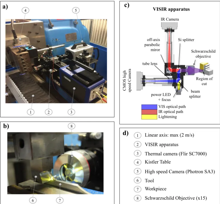
2. Experimentalapproach 2.1. Acquisitionandmachiningdevices
ThankstoVISIRapparatus,thesimultaneousmeasurementofstrains, strainratesandtemperaturesattooltipvicinityispossible.The develop-mentandcalibrationsofthisapparatusaredescribedinaprevious com-munication[49].AsdepictedinFig.1bthesceneofcutisilluminated through acollimatedwhite-lightLED(∼ 1 Watt)which isintegrated
Kistler Table
Thermal camera (Flir SC7000)
High speed Camera (Photron SA3)
Linear axis: max (2 m/s)
a)
VISIR apparatus
IR Camera
CMOS h
ig
h
sp
eed
Cam
era
Si splitter
beam
splitter
Region of
cut
off-axis
parabolic
miror
power LED
+ focus
Schwarzschild
objective
tube lens
VIS optical path
IR optical path
Lightening
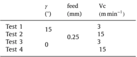
b)
Tool
Workpiece
Schwarzschild Objective (x15)
c)
VISIR apparatus
3
1
2
4
5
6
7
8
1
2
3
4
5
6
7
8
d)
Fig.1. Orthogonalcuttingexperimentalsetup:a)linearactuator,cuttingtoolandopticalapparatusb)closeupviewofthecutc)VIS-IRapparatusdetaileddesign d) nomenclature.
withintheVISIRopticalsystem.Theradiationemittedbytheworkpiece andreceivedbythereflectiveobjective,overarangeofwavelengths,is dividedintwopathsbythemeanofathinsiliconsplitter.Thislatter hastheparticularitytoreflects allofradiationbelow2μmof wave-lengthstothevisibleopticalpathandtransmittherestintheinfrared opticalpathasdescribedintheFig.1c.Then,theradiationsarefocused inthecamerassensorsbymeansofmirrors.Itmustbementionedthat thechromaticaberrationsarecorrectedthroughachromaticlenswhich wereinsertedinbothpaths.
Inordertorespecttheorthogonalcuttingconfiguration,adedicated device,calledDEXTER, madeof afixedtoolandalinearactuatoris used.Thislatterisfixedontheworkingplateofaconventionalmilling machinewhile thetoolis fixedon thespindle headaspresented in
Fig.1a.Cuttingforcesweremeasuredusinga6-components dynamome-ter(Kistler9257A).
2.2. Workpieceandtool
Inthepresentwork,thematerialunderinvestigationisthe Ti-6Al-4V(grade5)titaniumalloy.Itschemicalcompositionwasanalyzedby spark-opticalemissionspectrometryandisreportedintheTable1.It shouldbe mentionedthatthestudiedmaterialistemperedat1000K andthe𝛽-transusisaround1233K.Itsaveragegrainsizeismeasured around19.2μm.
ThemicrostructurehasbeeninvestigatedthroughSEMandis de-scribedinFig.2aandb.Itischaracterizedbyaduplexmicrosturcture composedbyprimary𝛼 grains(hexagonalclose-packedstructure) sur-roundedbytransformed𝛽 grains(bodycentrecubicstructure).
Themachinedspecimen(100× 40× 3mm3)waspolishedandetched
in ordertoreveal themicrostructureprovidinganaturalspecklefor digitalimagecorrelation(DIC).
Table1
ChemicalcompositionofthestudiedTi-6Al-4Vtitaniumalloy.
Ti % Al % V % Fe % Nb ppm Si ppm Cr ppm Cu ppm Ni ppm Pd ppm Mo ppm Co ppm C ppm B ppm
88,98 6,395 4,282 0,156 410 280 180 180 130 120 110 110 72 29
Fig.2. (a)InitialmicrostructureofthemachinedTi-6Al-4V(grade5)-equiaxstructure(b)𝛼 and𝛽 phasesofthematerial.
Table2
Cuttingvelocity,feedandrakeanglesused.
𝛾 (°) feed (mm) Vc ( m min −1) Test 1 15 3 Test 2 0.25 15 Test 3 0 3 Test 4 15
Twouncoatedcarbidetoolswereusedwithtwodifferentrakeangles (𝛾 =0◦,15◦).Theybothpresentaclearanceangleof𝛼 =11◦andaradius edgearound20μm.
2.3. Acquisitionandmachiningconditions
Inordertoovercomethemotionblurphenomenonthatoccurs dur-ingimagerecording,agoodcompromise betweentheparametersfor eachcamera(integrationtime,acquisitionfrequency,resolution,...)and cuttingconditions(cuttingspeed,feed,...)mustbeachieved.Therefore, opticalandmachiningparametersarefixedrespectivelyforeachtestas describedinTables2and3.Foreachtool,afeedof0.25mmisselected andtwocuttingspeeds(Vc)areinvestigated.
ThehighspeedcameraonthevisibleopticalpathisaPhotron Fast-camSA3.ItsacquisitionfrequencyFwassetto6000fpsandthe expo-suretime(itvis )variesbetween30and50μsdependingonthecutting
speed.AFlirSC7000thermalcamerawasusedintheinfraredpath(IR). Itissetat600fpsandanexposuretimeof𝑖𝑡𝐼𝑅 =30μsprovidinga ther-malimagesizeof160×128pix2.Thesimultaneouscamerastriggering
wasconductedthroughadedicatedboxsynchronization.
Formagnificationassessmentpurpose,themetricratio(R)was eval-uatedforthevisiblecamera(PhotronFastcamSA3)at1.133μm/pixand at1.981μm/pixforthethermalcamera.Readerscouldreferto[49]for thethermalcameracalibration.
2.4. Experimentalpost-processing
2.4.1. Digitalimagecorrelationandkinematicfieldscalculations
Thedigitalimagecorrelation(DIC)isperformedusing7Dsoftware
[50].Asdetailedinapreviouswork[49],thesizeofthesubsetis opti-mizedthroughtwoapproaches(MeanIntensityGradientandRigidbody methods).Hence,itissetto16×16pixforastandarddeviationofthe measureddisplacementsabout0.03pix.However,cumulatingsuch er-rorover50imagesleadtoamaximalerrorof1.5pixandthereforelead toerrorsonstrainbelow10%(ifa16×16pixextensiometricbasisis used).
Theincrementalcorrelationwasusedforkinematicfields calcula-tions(i.e.displacements,strainandstrainrate).Thisapproachis recom-mendedinthecaseoflargedeformation,highstrainrate,out-of-plane motionandmaterialdecohesion[19,51].Incontrast,itrequiresaproper numericalprocessinginordertocomputethecumulateddisplacements andstrains.Accordingly,thecumulateddisplacementstrategydetailed Table3
Opticalparametersusedforeachtest.
itIR (μs) itvis (μs) R (μm/pix) Image IR size (pix × pix) Image visible size (pix × pix) F (fps)
IR visible IR visible
Test 1 50 512 × 512
Test 2 50 30 1.981 1.133 160 × 128 384 × 352 600 6000
Test 3 50 512 × 512
in[19,49]wasusedinordertoenhancetheassessmentofthekinematic fields.Furthermore,theuseofsuchastrategyoffersastraightforward comparisonbetweenexperimentalresultsandnumericalsimulationsin termsoflogarithmicequivalentstrain(HENKY)Handequivalentstrain rateD.It’sworthmentioningthatthestrainratetensoriscalculated bymeansofthedisplacementincrements(ΔUx ,ΔUy ).Theknowledge ofthisparameteroffersastraightforwardaccesstothevelocityfields VxandVy.Assumingaconstantcaptureratesoftheimages,it there-forecomes𝑉𝑥 =Δ𝑈𝑥 ∕Δ𝑡and𝑉𝑦 =Δ𝑈𝑦 ∕Δ𝑡.Thenthecomponentsofthe strainratetensorDare:
⎧ ⎪ ⎪ ⎨ ⎪ ⎪ ⎩ 𝔻𝑥𝑥 (𝑥𝑘 ,𝑦𝑘 ,𝑘)= 𝜕𝑉 𝑥(𝑥 𝜕𝑥 𝑘,𝑦 𝑘𝑘,𝑘 ) 𝔻𝑦𝑦 (𝑥𝑘 ,𝑦𝑘 ,𝑘)= 𝜕𝑉 𝑦(𝑥 𝜕𝑦 𝑘,𝑦 𝑘,𝑘 ) 𝑘 𝔻𝑥𝑦 (𝑥𝑘 ,𝑦𝑘 ,𝑘)=1 2 (𝜕𝑉 𝑦(𝑥 𝑘,𝑦 𝑘,𝑘 ) 𝜕𝑥 𝑘 + 𝜕𝑉 𝑥(𝑥 𝑘,𝑦 𝑘,𝑘 ) 𝜕𝑦 𝑘 ) (1)
where(xk ,yk )arethegridcoordinates(identicalforeveryimagepair) fortheimagek.Readerscanreferto[19]formoredetails.
2.4.2. Energybalanceanalysis
Comingfromfirstandsecondlawsofthethermodynamic,theheat equationis thebasicingredienttoinvestigate thethermomechanical aspectofthecuttingprocess.Thespecificformofthevolumeheat dif-fusionequationintheLagrangianconfigurationappliedtoa2D ther-mographicframeworkcanbeexpressedas:
𝝆𝐂𝐩 ( 𝜕̄𝜃 𝜕𝑡 +⃗𝑣⋅ ⃗∇̄𝜃 ) −𝑘1 ( ⃗∇̄𝜃)2−𝐤Δ2̄𝜃 + 2ℎ𝜃 𝑒 + 2𝜎𝜖 𝑒 (̄𝑇4−𝑇𝑟 4) ⏟⏞⏞⏞⏞⏞⏞⏞⏞⏞⏞⏞⏞⏞⏞⏞⏞⏞⏞⏞⏞⏞⏞⏞⏞⏞⏞⏞⏞⏞⏞⏞⏞⏞⏞⏞⏞⏞⏞⏞⏞⏞⏞⏞⏞⏞⏞⏞⏞⏞⏞⏞⏞⏞⏟⏞⏞⏞⏞⏞⏞⏞⏞⏞⏞⏞⏞⏞⏞⏞⏞⏞⏞⏞⏞⏞⏞⏞⏞⏞⏞⏞⏞⏞⏞⏞⏞⏞⏞⏞⏞⏞⏞⏞⏞⏞⏞⏞⏞⏞⏞⏞⏞⏞⏞⏞⏞⏞⏟ Experimentalevaluation = 𝑤′𝑐ℎ =𝛽(𝜎 ∶ ̇𝜖𝑝 ) ⏟⏞⏞⏞⏞⏞⏞⏞⏞⏟⏞⏞⏞⏞⏞⏞⏞⏞⏟ Numericalevaluation (2) where:
• ̄𝜃 =̄𝑇(𝐱,𝐭)−𝑇0isthedifferencebetweenthecurrentandtheinitial temperatureT0.
• 𝝆𝐂𝐩(𝜕 ̄𝜃 𝜕𝑡 +𝑣∇̄𝜃
)
istheintertialtermthatlinksthetemperature evo-lutionatagivenlocation(x,t).Variablevstandsforthevelocity vectorfield.
• 𝑘1(⃗∇̄𝜃)2−𝐤Δ2̄𝜃 isthediffusion(Laplace’s)term.Notethat∇isthe
twodimensionnalgradient andΔ2 thetwo-dimensionnalLaplace
operator.
• 2ℎ𝜃 𝑒 +
2𝜎𝜖
𝑒 (𝑇4−𝑇𝑟 4)aretheconvectiveandradiativeheatlossesover
thefront andbackfaces of the sample. 𝜎 stands for the Stefan-Boltzmanconstant. histheheattransfercoefficientchosen tobe equal50Wm−2K−1.T
r istheroomtemperature.However,this
quan-tityhasbeenassessedandcomparedtolaplacianandinertialterms inpreviouswork[49].Accordingly,itwasneglegtedinthepresent analysis.
• 𝑤′
𝑐ℎ=𝑑1=𝛽
(
𝜎 ∶ ̇𝜖𝑝 )istheheatsourcetermandequalstheintrinsic
dissipationd1inabsenceofthethermoelasticcouplings.𝛽,𝜎, ̇𝜖𝑝 are
respectivelytheTaylorQuinneyfactor,theCauchystresstensorand thestrainratetensor.
• Thematerial parameters arethen 𝝆 =𝜌1𝜃 +𝜌0 the massdensity, 𝐂𝐩=𝐶1𝜃 +𝐶0 thespecificheat,𝐤=𝑘1𝜃 +𝑘0 thethermal
conduc-tivity.Accordingto[52,53],theywerechosentoevolvelinearlyas afunctionoftemperature(seeTable5).
Ratherthantemperatureandkinematicsfieldsanalysis,theobjective oftheexperimentalpartistoassessthelefthandsidetermsfromthe measuredquantities(̄𝑇(𝐱,𝐭)andT0)inordertoprovideanestimationof theinvolvedpowerinthecuttingphenomenon𝑤′
𝑐ℎ.Itisthencompared
withtherighthandsidetermwhichisevaluatednumericallyfromthe intrinsicdissipationd1(seeSection5.6).
Table4
Thenumberofthecaptured im-ages for the analyzed segment chip. Number of images IR Visible Test 1 5 58 Test 2 1 10 Test 3 6 62 Test 4 1 11 3. Experimentalresults
Onlyonesegmentisinvestigatedformeachcapturedvideo.For read-ingandcomparisonpurpose,imagesarelabelledbytheirnumberand thepercentageof thesegmentformation.Thefirstimage(0%)being theimagewherethesegmentfirsttouchesthetoolandthelastimage (100%)beingtheimageexhibitingadisplacementof50μmafterthe segmentbeingfullyformed.TheTable4resumethenumberofimages obtainedforeachtest.
Asmentionedinthepreviouswork[49],onlyonethermalimageis acquiredduringtheprocessat15m/min.Itcorrespondstoa40% pro-gressionofthesegment.Consequently,otherthermalimagesfromother measuredsegmentswhichhave,approximately,thesamesizewere se-lectedfortheanalysis.Itshouldbementionedthatnoimportantdrift ofthethermomechanicalquantitieswasobservedduringthecut.
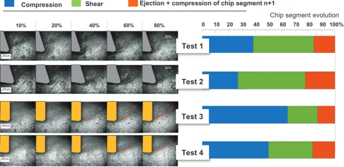
However,experimental investigationson thechipgenesislead to splitthemechanismintothreesuccessivesteps[3,19,20].During the firststage(i.e.compressionstep),ahighcompressionstateonthe mate-rialisinducedbythetoolandlocatedaroundthecuttingedge.The seg-mentstorestheelasticenergywhileplasticitydevelopsintheprimary shearzone.Anoutofplaneswellingofthesegmentisclearlyvisiblein thisphase.Theendofthisstageisdefinedbytheshearplanecreation andtheuprisingofamicrocrackatthetooltip.Duringtheshearphase, thecrackinitiatesatthetooltipandevolvesinsidetheshearzone to-wardthefreechipsurface.Finally,thesegmentisfullyformedandslips onboththecuttingfaceandthenextsegment(tobeformed). Simul-taneously,thetooltipstartsthecompressionphaseofthenextone.As depictedinFig.3theclassicalstepsofthechipformationwereobserved andanalysedforeachtest.
SuchgraphresultingfromaDICanalysisbasedonminorandmajor strains(notpresentedhere)asdetailedin[19,20].Itisclearly percepti-blethatthethreesuccessivessub-processesarehighlyinfluencedbythe cuttingconditions.Firstly,itcanbepointedoutthatthecompression phaseismoreimportantwithanullrakeangle.Thelongdurationof thecompressionphaseleadstoarapidshearphaseandtoaparticular chipgenesisway.Indeed,duringthecompressionphase,thesegment storeselasticenergywhichisthendissipatedinthenextstages.Hence, thelongerthecompressionphaselaststhefasteristhesegmentejection (i.e.shortshearandextractionphases).
Thecompressionphaseisalsoaffectedbythecuttingvelocity.As shownin thetests 1and3(𝑉𝑐=3mmin−1),this phaselastslonger
thaninthecaseoftests2and4(𝑉𝑐=15mmin−1).
Ontheotherhand,itcanbeseenthatcrackpropagationisdelayed whenlowcuttingspeedareinvolved.Thisobservationbringstolight thecuttingvelocityeffectinthestrainlocalizationandthusonthecrack propagation.Therakeangleeffectonthestrainlocalizationandcrack propagationisclearlyshownintheFig.3.Acurvedstrainlocalization zoneisalwaysobservedwithanullrakeanglewhereasitislinearwith arakeangleof15∘.Thiscrackpathtransitionfromcurvedtolinearmay
resultsfromtheshapeofthetriaxialityzone.Asdetailedin[19,20],a hydrostaticpressurezoneislocatedatthetooltipwhichishigher(in termsofmagnitudeandgeometry)inthecaseofnullrakeanglethan thepositiveone(duetotheadditionalcompressioninducedbytherake
80% 80%
80%
Fig.3.5instantsnapshotpicturesacquiredduringthegenerationofonesegmentforthefourinvestigatedcuttingconditions.Thedistinctionbetweenthethree phasesoftheprocessreliesonthecrackpropagation.Thetimeelapsedin-betweencrackinitiationandcompletiondefinestheshearphase.
angle).Duringthesegmentgeneration,thecrackskirtsthetriaxiality zoneinordertoreachthefreesidesurface.Thislatterbeingnarrower forastherakeangleincrease,thecrackcanreachthefreesurfacein astraightmanner.Consequently,thelargeristhetriaxialityzonethe morecurvedisthecrackpath.
3.1. Kinematicfields
Fig.4presents theevolution ofthe logarithmicequivalentstrain (a.k.aHencky’sstrain)duringchipsegmentformation.Strain localiza-tionsareclearlyhighlightedbysignificantstrainmagnitudes(upto1.7). Duringcompressionphase,thestrainmagnitudeislowandseemshighly heterogeneousinspaceandintime.Then,thestrainlocalizationstarts tomoveforwarduptotheshearplanecreation.Finally,astrainingband isobservedwhichisfixedinspaceandonlyfluctuatesinmagnitudeover time.Thestrainlocalizationthicknessishighlydependentonthecutting speedforbothrakeangles.Itdecreasesasthecuttingspeedincreases. Thisinformationprovesthatstrainlocalizationismainlyresultsfrom thecuttingspeedwhilestrainmagnitudeisinfluencedprimarilybythe rakeanglevariationandatlesserscalebythecuttingvelocity.Onthe otherhand,itcanbenoticedthatthechipbulk(i.e.thesidesurfaceof thechipwhichlocatedawayfromthefirstandsecondshearzones)is notsignificantlydeformedwhenthecuttingspeedvaries.Conversely,it seemstobeinfluencedbythevariationoftherakeangle.
Thestrainratesarealsogreatlyinfluencedbythecuttingspeed.A highstrainratesmagnitudeisobservedforearlystageofthesegment chipformation(~ 20%).Thisphenomenonplaysaleadroleforstrain localizationandcrackpropagationsincetheequivalentstrainatfailure decreasesathighcuttingspeed.Consequently,itleadstoarapid seg-mentchipformation.However,therakeangleinfluenceonthestrain rateisnotnegligible[19,49].Adropof50%inthestrainrateis ob-servedatlowcuttingvelocity.Conversely,thiseffectisnotobservedat 15mmin−1whereacomparablemagnitudeisobtained.
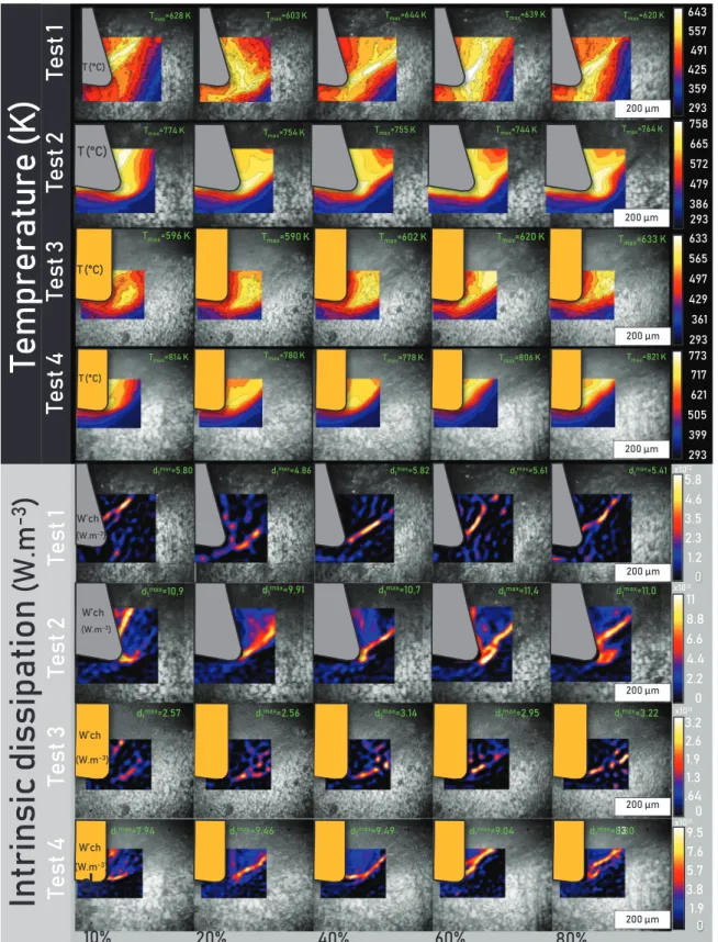
3.2. Thermalfields
Fig.5depictsthetemperatureandintrinsicdissipationdistributions duringchipsegmentformation.Thetemperatureincreaseswiththe cut-tingvelocityaugmentationandat alesser scalewiththerakeangle diminution.
Atlowcuttingspeedandusinga0∘rakeangle,noclearlocalizationis
foundbefore60%ofsegmentformation.However,byvaryingtherake angleto15∘,anearliertemperaturelocalizationisobserved(i.e.at40%
ofthesegmentformation).Foralltests,themaximumtemperaturedoes notevolvesignificantlyduringthesequence,onlyrangingfrom590K to633K.However,thetemperaturegradientissignificantinspace.The min/maxrangewithinthesameimageisaround573Kmm−1.Indeed,
themaintemperatureriseseemstooccurduringthetransitofa mate-rialpointthroughtheprimaryshearzone.Italsoshouldbementioned thatthemaximumtemperaturelocationislocatedintheprimaryshear zone(ZI).SuchfindingsleadtoconsiderthatheatgeneratedinZI(from plasticityanddamage)ismoreimportantthaninthesecondaryand ter-tiaryshearzoneswherefrictionisoftenassumedtoplayaleadingrole. Itcanbeexplainedbytheshortperiodofmachining(∼ 1.2s)which cor-respondstoatransitionalstage.Itisworthremindingthatonlyasmall partofthesecondaryshearzoneiscapturedbythethermalcamera dur-ingtheprocess.Indeed,furtherinvestigationswithathermalimageof thewholesceneofcutneedtobeconductedtobeconclusiveonthis matter.
Converselytotemperature,alocalizationoftheintrinsicdissipation isobservedatearlystageofchipsegmentformation.Sucheffectis de-tectedespeciallyathighcuttingspeed.Thedissipatedpowerevolution canbedescribedthroughthreestages:atfirst ~ 20%,thedissipated powerislowandisconcentratedatthetooltip.Then,fromaprogression in-between~ 20%to~ 60%,thedissipatedpowerincreasesandmoves towardthemiddleoftheprimaryshearzone.Duringthefinalstageof thesegmentchipformation,itisseenfromthelatestimagesthateven whilethecrackpropagationiscompleted,andthatstrainaccumulation stalls,thegeneratedpowerremainshigh.Thethermal source magni-tudeincreasesby43%whenmultiplyingby5thecuttingspeedanda smallreductionisobservedbyvaryingtherakeangleto0∘.These
obser-vationsseemnotsurprisingconsideringthehighlocalizationobserved witharakeangleof15∘andespeciallyathighcuttingspeed.In
addi-tion,itisclearlyperceptiblethattheadditionalcompressioninduced bythenullrakeangledisruptstheshearmechanismsandconsequently thelocalizationphenomena.Theheatsourceinthiscaseseemsmore importantinthespacebutwithasmallermagnitudethaninthecaseof tests1and2.
Itshouldbementionedthatthegenerationofsegmentnoverlaps withtheonegeneration𝑛−1.ItisvisiblefromFig.5at10%(forall
Fig.4. 5instantimagesofthestrainandstrain-ratefieldsdistributionsduringthegenerationprocessofonesinglesegment.Thefourcuttingconditionsunder investigationaredepicted(3m∕min−15m∕minand0◦−15◦).
machiningcondition)thattwoheatsourcesareactivesimultaneously: theupperonecorrespondingtotheslidingofsegment𝑛−1andslightly beaneaththedissipationduetotheearlystageofcompressionin seg-mentn.theinputmechanicalpowerissplitintwolocations,thefirst consistsintheslidingofthesegmentn-1overthesegmentnandthe secondistheearlystageofgeneratingsegmentn.
Thepreviousexperimentalsectionbringstolightthe thermomechan-icalaspectoftheTi-6Al-4Vchipformation.Thekinematicsand ther-malfieldsevolutionsarepresentedanddiscussed.Thestrain localiza-tionphenomenonplaysanimportantroleintheshearplanecreation. Itsmagnitudeismainlypilotedbythecuttingvelocityanditsshapeis stronglyrelatedtothecuttinggeometry(i.e.therakeangleandfeed).
Fig.5. 5instantimagesofthetemperatureandintrinsicdissipationdistributionsduringthegenerationprocessofonesinglesegment.Thefourcuttingconditions underinvestigationaredepicted(3m∕min−15m∕min and 0◦−15◦).
Fromathermalstandpoint,themaximumtemperatureisusually lo-catedintheprimaryshearzone.Itsmagnitudeismainlyinfluencedby thecuttingspeedandatalesserscalebytherakeangle.Byhighlighting bothFigs.4and5,onecanthereforeprovethattheequivalentstrainat failureissmallerathighcuttingspeedeventhoughthetemperaturein theprimaryshearzoneishigher.Thisresulttestifiesthelossof
ductil-ityofmaterialfollowingacompetitionwiththestrainsofteninginthis rangeofthermomechanicalloading.
Thespecificpowerisalsoinfluencedbythemachiningparameters. Thethinstrainingbandinducedathighcuttingspeedleadstoahigh concentrationoftheintrinsicdissipation.However,thedissipationin thesegmentbulkandinthesub-surfaceisfarfromnegligible.Further
Fig.6. Geometryandboundaryconditionsusedfortheimplementationofa3DFEorthogonalcuttingmodel.
investigationsarerequiredtolinkthisphenomenontothesurface in-tegrity(i.e.residualstresses,...)ofthegeneratedsurface.
4. Numericalapproach
4.1. 3Dgeometricfinite-element(FE)model,boundaryconditionsand meshsensitivity
The3Dgeometricmodelproposedconsistsinacarbidecuttingtool andapartmadeofTitaniumalloyTi-6Al-4V.Theworkpiecetomachine ismodelledasaparallelepipedmeasuring10mminlength,1.7mmin heightand1.5mminwidth(𝑤=3mmbutaplaneofsymmetryis de-fined).Itwascreatedbyasinglepartinordertorespectthephysical phenomenainordertoavoidmanymodelinghypotheses.Thetool ge-ometryandthecuttingconditionsarethesameasfortheexperimental study.
AsdetailedinFig.6,the3Dfiniteelementmodeliscreatedunder symmetricconditioninordertoinvestigatetheevolutionofthechip mechanismeither underplanestrain assumption(center of thechip
𝑧=𝑤∕2)andplanestressassumption(sidefreesurface𝑧=0).Theback surfaceofthetoolislockedover6dof.Thebottomsurfaceofthe work-pieceisonlyfreetotranslatealongtheXaxis.Thedisplacementofthe nodesonthebacksurfaceoftheworkpieceisimposedwithaconstant velocitythatequalsthedesiredcuttingspeed.However,heattransferis allowedonlybetweenthetwoparts.
3Dcontinuumelementsunderreducedintegration(C3D8RT)were adoptedforthermomechanicalfieldscalculation.Regardingthe hour-glasscontrol,arelaxstiffnessmethodisusedtopreventhourglassingas recommendedbyBargeetal.[54].
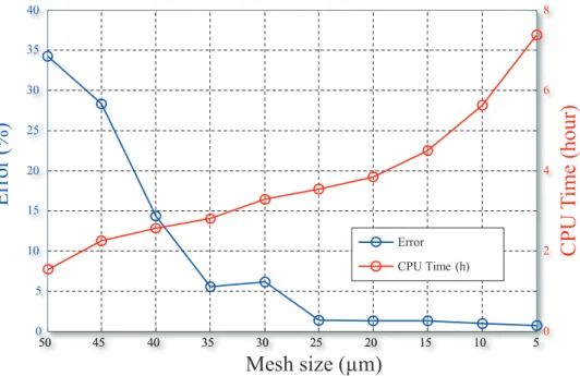
Tomakeacompromisebetweenbothcomputingcostandaccuracy, ameshsensitivityanalysisiscomputedusinganiterativemethod. Ac-cordingly,aseriesofsimulationsarecarriedoutbyvaryingthe charac-teristiclengthofelement(L)from55μmto5μmwithanincerementof 5μm.Foreachsimulation,bothaverageandmaximumofthecutting forces(xdirection)arerecordedfortheerrorcalculation.Hence,the
erroriscalculatedbetweentwosuccessivesmeshsize(i.e.iand𝑖−1) asfollows: 𝑀𝑒𝑠ℎ𝑒𝑟𝑟𝑜𝑟𝑖 (%)= √( 𝑎𝑣𝑒𝑟𝑎𝑔𝑒(𝐹𝑐)𝑖 −𝑎𝑣𝑒𝑟𝑎𝑔𝑒(𝐹𝑐)𝑖 −1 𝑚𝑎𝑥(𝐹𝑐)𝑖 )2 × 100 𝑤ℎ𝑒𝑟𝑒𝑖=0𝑡𝑜10 (3)
AsdepictedinFig.7,theerrorseemstobestablefrom25μmofthe meshlengthforacomputingtimeof3hand37min.Inaddition,the chipformationshowsthatfrom thisvalueofthecharacteristicmesh lengthcanwellcapturetheshearlocalizationandthecrackpropagation onthechip.Consequently,themeshsize25×25×115μm3waschosen
intheregionofinterestandbeyondthiszoneacoarsestmeshisadopted whichisrangesin-between(200× 300× 115−500× 300× 115μm3).
4.2. Materialconstitutiveanddamagelaws
Themechanicalbehaviorofthecarbidetoolismodelledbya clas-sicalthermo-elasticlaw.Themechanicalparametersoftheworkpiece andthecarbidetool(WC)aregiveninTable5.
Sincethetightcouplingbetweenphenomena(mainlybetween tem-peratureandstrainrate)thatoccursduringthechipformation,the mas-teryofworkpiecebehavioranddamageevolutionisessential.Therefore, theworkpiecebehaviorismodelledbyamodifiedLudwicklaw under-takingatightcouplingbetweentemperatureandstrainrate.Thismodel ispresentedintheEq.(4)oftheequivalentplasticflowstress.
𝜎 =𝐴(̇𝜀,𝑇)+𝐵(̇𝜀,𝑇).𝜀𝑛 (̇𝜀 ,𝑇 ) (4)
where𝐴(̇𝜀,𝑇),𝐵(̇𝜀,𝑇), 𝑛(̇𝜀,𝑇)arerespectivelytheyield strength,the hardeningmodulusandthehardeningcoefficientandexhibita depen-dencyonboththestrainrateandtemperature.However,theevolutions ofeachparameteraccordingtothesetwoquantitiesweredescribedby abilinearinterpolationasdetailedinapreviouswork[20].
Thedamagemodelingclassicallyreliesonacumulativeformulation ofthedamageinternalvariableD,ofwhichtheevolutionthroughout
Fig.7. Meshsizesensitivityanalysis. Depic-tionoftheevolutionsof:(i)theerroronthe globalcuttingforceand(ii)theCPUtime,asa functionofthemeshsize.(CPUcharacteristics: AMDopteron6376/2processors16Cores/ 2.3GHZ/RAM132Go).
Table5
MechanicalandthermalpropertiesofthecarbidetoolandTi-6Al-4Vworkpiece(20◦C−550◦C)[6,52,53].
Properties Material
Ti-6Al-4V WC
Young modulus E (GPa) 118 . 8 − 0 . 09 .𝑇 705 Density 𝝆(kg m −3 ) 4452 − 0 . 1 𝑇 15,700 Poisson’s ratio ϑ 0.33 0.23 Specific heat 𝑪 𝒑 ( J −1 K −1 ) 552 . 8 + 0 . 358 .𝑇 −2 . 10 −4 .𝑇 2 + 0 . 313 .𝑇 + 220 Thermal conductivity 𝒌 (W m −1 𝐾 −1 ) 6 . 58 + 0 . 0057 .𝑇 −8 . 10 −5 .𝑇 2 + 0 . 07 .𝑇 + 43 . 1 Expansion Coefficient 𝜶𝒅 ( K −1 ) 1 . 15 −5 5 . 10 −6 Room temperature 𝑇 𝑟 ( K ) 293 293 Fusion temperature 𝑇 𝑓 ( K) 1903 − Taylor-Quinney coefficient 0.8 −
plasticityisdefinedasafunctionoftheincrementofplasticstraind𝜀p
by:
̇𝐷 =𝑑𝜀𝑝
̄𝜀𝑓 (5)
Suchformalismrequiresagoodassessmentofthestrainatfailurē𝜀𝑓 .In
fact,theshearnatureofthemechanismandthenarrowrangeofstress triaxiality𝜂 involvedin cutting(𝑎𝑝𝑝𝑟𝑜𝑥𝑖𝑚𝑎𝑡𝑒𝑙𝑦−0.33<𝜂 <0.33)have ledtoconsidermaxshearfailurecriterionaswellsuitedforthis inves-tigation[20].Thislawcanbedescribedasafunctionofthenormalized Lodeanglē𝜃 byEq.(6).
̄𝜀𝑓 = ⎡ ⎢ ⎢ ⎢ ⎣ √ 3𝜏𝑓 (̇𝜀,𝑇) 𝐵(̇𝜀,𝑇)𝑐𝑜𝑠(𝜋 ̄𝜃 6 ) −𝐴𝐵((̇𝜀̇𝜀,,𝑇𝑇)) ⎤ ⎥ ⎥ ⎥ ⎦ −1 𝑛(̇𝜀,𝑇) (6)
Thestrainrateandtemperaturedependencyisthusaddressedthrough the material parameters and the maximum shear stress at failure
𝜏𝑓 (̇𝜀,𝑇).Thelatteristheonlyparametertocalibrateandisdescribed
asafunctionoftemperatureandstrainratebyabilinearinterpolation asdetailedin[20].TheplaneequationisrecalledinEq.(7)whereas theparametersvaluesusedinsimulationsarespecifiedinTable6.Itis importanttonotethatthedamageandbehaviorlawsaresuccessfully implementedintheFEmodelbymeansofVUMATsubroutine.
𝐴,𝐵,𝑛,𝜏𝑓 =−𝑎.𝑇−𝑏.𝑙𝑛(̇𝜀𝑝 )−𝑐 (7)
Table6
Behavioranddamagelawparameters[20].
A (Pa) B (Pa) n 𝜏f (Pa)
a 9 . 36 𝑒 + 005 5 . 57 𝑒 + 05 9 . 46 𝑒 − 05 7 . 1716 𝑒 + 05
b −1 . 45 𝑒 + 08 4 . 66 𝑒 + 07 4 . 23 𝑒 − 02 9 . 3088 𝑒 + 07
c −8 . 65 𝑒 + 08 −6 . 39 𝑒 + 08 −0 . 365 6 . 9573 𝑒 + 08
4.3. Contactconditionsandfrictionmodeling
Inadditiontobehavioranddamagelaws,thesimulationofthechip formationprocessalsorequiresagooddescriptionoftheinteraction be-tweenthetoolandworkpiece.Therefore,aparticularattentionispaidto thefrictionmodel.Asprovedbyseveralauthors,thetool/chipinterface canbedividedintwodistinctregionswherethetribologicalbehavior isclearlydifferent[55–57].Thefirstregion(i.e.stickregion)islocated aroundthetooltipandischaracterizedbyastrongmaterialadhesion duetohighcontactpressure.Thesecondregion(i.e.slipregion)is char-acterizedbyaslidingmotionofthechipalongtherakeface.
Inthepresentstudy,anewstick-slipfrictionmodelisproposedas formulatedinEq.(8)anddescribedinFig.6(detailA).Accordingly, thestickregionwasdescribedbyaTrescafrictionlawwithacoefficient valuemk equaltotheunity[27].Ontheotherhand,theslidingregion ismodelledbyamodifiedCoulombfrictionlawwhichfriction param-eter𝜇 isdescribedasafunctionoftheslidingvelocityVsl asproposed in[58].𝜎n and𝜏 representrespectivelythenormalandshearfriction
stresses. ⎧ ⎪ ⎨ ⎪ ⎩ |𝜏|=−𝑚𝑘 .√𝜎𝑛 3. ⃖⃖⃖⃗ 𝑉 𝑠𝑙
||⃖⃖⃖⃗𝑉 𝑠𝑙||∶Trescafrictionlaw(forstickregion)
|𝜏|=−𝜇(𝑉𝑠𝑙 ).𝜎𝑛 . ⃖⃖⃖⃗𝑉 𝑠𝑙
||⃖⃖⃖⃗𝑉 𝑠𝑙||∶ModifiedCoulombfrictionlaw(forslidingregion)
(8) AspointedoutbyBodwenandTabor[59],theapparentfriction pa-rameterresultsfromtwocontributions.Itincludesononehandthe ad-hesivephenomena,thatareaffectedbythematerialpropertiessuchas hardness,asperities,andontheotherhandtheplasticdeformationof theworkmaterial,whichcannotbeneglectedundersuchseverecontact conditions.Basedonthisconsideration,severalstudiesprovedthatthe adhesivepartoftheapparentfrictionparameteriscloseto90%inthe caseoftitaniumalloyTi-6Al-4V[58,60].Accordingly,onlythe adhe-sivepartisintroducedinsimulations.Thefrictionlawissuccessfully implementedinthenumericalmodelthroughVfricusersubroutine.
Anotherimportantfeatureofthemodelistheheatpartition coeffi-cient𝛽p .Itdefinestheratioofthefrictionthermalpowerthatspreads
withinthetoolT (andthus 1−𝛽𝑝 withintheworkpieceW).Several modelshaveproposeddifferentapproachesintheassessmentofsuch coefficient[61,62].ThemostrecentapproachesreliesontheThermal ContactResistance(TCR)whichassessmentisadedicated experimen-talchallengeinitsownright[63,64].Inthepresentwork,theoriginal approachproposedbyBlok[61]andJaeger[62]hasbeenchosen.This latterdoesnotrequiretheevaluationoftheTCRbutratherdefines𝛽p
asaratioofthermaleffusivitesofthetool𝜁T andworkpiece𝜁W inthe
caseofadynamiccontact.Suchdefinitionhasalreadybeensuccessfully implementinthefieldsofcuttingsimulation[3,38]andreads:
𝛽𝑝 = 𝜁𝑇
𝜁𝑇 +𝜁𝑊 ×√𝑃𝑒
where 𝜁𝑖 =√𝝆𝑖 .𝑪𝒑𝑖 .𝒌𝑖 and𝑃𝑒 =𝐿×𝑉𝑠 ×𝝆𝑊 ×𝑪𝒑𝑊
4×𝒌𝑊 𝑖=𝑇,𝑊 (9) where, Pe is the Peclet number, Vs the sliding velocity and L the contact width. The evaluation of the Peclet number re-quires the input of the sliding velocity which is an experimen-tal blind spot. Accordingly, four values of 𝛽p was calculated:
at (20◦C∕3mmin−1,500◦C∕3mmin−1;20◦C∕15mmin−1,500◦C∕15
mmin−1).ThematerialparametersforTungstenCarbideandTi-6Al-4V werethoseofTable5.Theobtainedvalues(0.58,0.56,0.75,0.74)was averagedtoobtainavalueof𝛽𝑝 =0.66whichwassetinthemodel.Its shouldbementionedthat90%oftheplasticworkinducedbyfrictions phenomenaisconvertedintoheat[3,20].
5. Numericalandexperimentalconfrontation
TheuseofcoupledmeasurementandFEsimulationsconstitutesa powerfultoolforinvestigationsandprovidesapreciousinsightofchips generationphenomenonfromwhich someconclusionscan be drawn butitalsobringsmanysubsequentquestions.Thepresentsectiondeals withthenumericalandexperimentalresultsobtainedfromorthogonal cuttingoftitaniumalloyTi-6Al-4V.Thecomparisonbetweenthetwo approachesisperformedthroughseveralaspects.Accordingly,the rel-ativeerroriscalculatedasdescribedinEq.(10).
𝐸𝑟𝑟𝑜𝑟(%)= √ √ √ √(𝑚𝑎𝑥(𝑂𝑢𝑡𝑝𝑢𝑡𝑛𝑢𝑚 )−𝑚𝑎𝑥(𝑂𝑢𝑡𝑝𝑢𝑡𝑒𝑥𝑝 ) 𝑚𝑎𝑥(𝑂𝑢𝑡𝑝𝑢𝑡𝑒𝑥𝑝 ) )2 × 100 (10) Thechipmorphologyisdiscussedandcuttingforcesarethus mon-itored andcompared.Moreover, aparticularattentionis paidtothe thermalaspectintermstemperatureevolutionandintrinsicdissipation duringthechipgeneration.
5.1. Chipmorphology
Fig.8depictsthenumericalchipmorpholgyaswellasthedamage fields obtained forthefourmachiningconditions. Alltheperformed cuttingtestsledtoserratedchips,generatedfromquasi-periodiccracks propagation. Chipssegmentsareseparatedbydamagedzones which emphasizethemagnitudeofthethermo-mechanicalloadingsandcracks propagationshistoryinducedduringtheprocess.Thecrackinitiatesat thesidefree surface,closetothetooltip andpropagateswithin the material.
Theclassicaldependencybetweenthecuttingspeedandthechip sizeis alsofound.The chipsizedecreasesasthecutting speedrises Fig.8. Chipmorphologiesobtainedfromthe FEmodelforthefourcuttingconditions.
Fig.9. NumericalvonMisesstressandstresstriaxialityfieldsforthedifferentmachiningconditionsat80%ofthesegmentformation.
Table7
Meanvaluesanderrorsofexperimentalandnumericalforcesunderallmachiningconditions.
𝛾 ( ∘) feed (mm) Vc (m min −1 ) 𝐹𝑐
exp Average Fcnum Average Fc error % 𝐹 𝑓 exp Average Ffnum Average Ff error %
Test 1 15 0.25 3 1463 1329 9.15 693 627 9.52
Test 2 15 1233 1153 6.48 512 473 7.61
Test 3 0 3 1611 1528 5.15 789 733 7.09
Test 4 15 1516 1435 5.34 745 689 7.51
higherresultinganimportantnumberofchipsegments.Itshouldbe mentionedthatasignificanttransversaldeformationofthechipsurface (outofplane)isobservedforallcuttingconditions.Asprovedbyseveral authors,thislatterphenomenonseemsaffectedmainlybytherakeangle andatalesserscalebythecuttingspeed[19,20,49].
Damageismainlyconcentratedintheprimaryandsecondaryshear zones.Thinbandsareobservedinthecaseoftestsperformedwith pos-itiverakeangleandspeciallyat15𝑚.𝑚𝑖𝑛−1. Inthecaseof thirdand
fourthtests,ahighermagnitudeofdamageisobservedinthechipbulk. AsillustratedbyFig.9a,theuseofanullrakeanglegivesbirthtoan additionalstressinthechipsegmentduringtheprocesswhichinduces deformationofthechipbulkandcreationofastronghydrostatic com-pressivezoneatthetooltip.
Fig.9b,showsthecomputedstresstriaxiality(triax)at80%ofthe chipevolutionfordifferentcuttingconditions.Itcanbeseenthatthe mechanicalloadingsdifferwiththerakeanglechanges.Forapositive rakeangle,itisclearlyfoundthatshearistheleadingmodeoffailure. However,acompressive/shearstateisnoticeableinthecaseofthethird andfourthtests.Duetothiseffect,thenumericalmaterialelementsare highlydeformedandstackedthereforeremovingasignificantpartof thedepictedcrackpathline.Ahydrostaticcompressivezoneisobserved nearbythetooltip.Itsshapeandmagnitudeseemsstronglyaffectedby therakeangleandatalesserscalebythecuttingspeed.Basedonthese observations,itappearsthattheshapeoftheshearplanemainlyresults fromtheshapeofthehydrostaticcompressivezone.Inthecaseofthe firstandthesecond tests,a simpleandlinearevolutionof thecrack propagationpathisobserved.Bycontrast,acurvedcrackpathshapeis foundinthecaseoftests3and4.Accordingly,thecrackpropagation seemstoavoidthehydrostaticcompressivezoneinordertoreachthe freesideofmaterial.Thesenumericalobservationsareverysimilarto theexperimentalones.Inaddition,itjustifiestheparticularchipshape foundwithnullrakeangleandbringstolightseveralchallengesabout theinfluenceofthehydrostaticpressureontheshapeandgeometryof theshearbandespecially, inthecaseof anisotropicmaterialswhere therelationbetweenstressandstraintriaxialityisnolongerstraight forward.
5.2. Cuttingforces
Asmentionedintheabovecuttingforcesaremeasuredthrough 6-componentsdynamometer (Kistler9257A).Unfortunately, itsnatural frequency (7kHz)istoolow incomparisonwithchipformation fre-quency.Inaddition,thegenerationof segmentnpartiallyoverlapin timebythegenerationofsegments𝑛−1and𝑛+1. Thisjustifiesthe difficultyinpost-processingmacroscopicforcesusingsuchdevice. Con-sequently,onlyaveragesofthecuttingandfeedforcesareconsidered andcomparedasdetailedinTable7.
Itcanbenotedthatbothcuttingandfeedforcesareaffectedmainly bytherakeangleandthecuttingvelocity.Itincreasesbyvaryingthe rakeangletowardnullvalueorbydecreasingthecuttingvelocity. Re-gardingthisissue,the3Dnumericalmodelpresentsagoodagreement withanacceptableerror.However,thenumericalforcesare underes-timatedinallsimulatedcases.Inaddition,theerrorseemstobemore meaningfulinthecaseofthefeedforceandspeciallyforthetest1.This underestimationcanbeoriginatingfrommanysources.Infact,the con-tactconditionsarehighlyinfluencedbytherakeanglevariationwhich isnottakenintoaccountinthisFEmodel.Inaddition,theuseofthe elementdeletionmethod,theassumptionofaconstantcuttingvelocity, andthechosenmeshsizecanalsobetheoriginoftheobtainederror. Ontheotherhandthecomputedcuttingforcesprovideabettermatch oftheexperimentaloneswhentherakeangleequals0∘.
5.3. Logarithmicstrain(Heq)
Fig.10aandballowthecomparisonbetweennumericaland exper-imentalstrainsinthechipsegment.Overalltests,thenumerical log-arithmicstrainseemsunderestimated.Eventthoughtheerrorissmall fortests3and4(~ 10%),itismorepronouncedinthecaseofpositive rakeangle(~ 24%).Thiserrorcanbemainlyattributedtothe simu-lationtechnique.Sincetheerodingelementtechniqueisemployedin FEsimulations,thestrainhighestcumulationisdiscardedalongwithits bearingelement.AsdepictedinFig.10c,agoodagreementbetween nu-mericalandexperimentalstrainpathsisobserved.Bycontrast,apartof
Fig.10. Numericalandexperimentaldistributionsofthelogarithmicstrainfields:Comparisonsat80%ofthesegmentformationandforalltests.(a)Numerical distributionofthelogarithmicstrain(b)Experimentaldistributionofthelogarithmicstrain(c)Logarithmicstrainpathsextractedfromthenumericalandexperimental results(seethearrowsdirections).Thenumericalstrainpeaksareerodedbythenumericalelementdeletiontechnique.
Fig.11. Numericalandexperimentaldistributionsofthestrainratefields:comparisonsat80%ofthesegmentformationandforalltests:a)numericalresultsb) experimentalresults.
thenumericalresponseisnotfound.Thisfindingleadstoconsiderthat thenumericalpeaksareremovedbytheerosionelementtechnique. De-spitethenumericalartifact,theFEmodelpresentsagoodsensitivityon thelogarithmicstrainasafunctionofthecuttingconditions.Alikethe experimentalobservations,themodelpredictsthatthestrainmagnitude decreasesbyvaryingtherakeanglefrom0∘to15∘.
5.4. Strainrate(Deq)
Numericalandexperimentalstrain ratefields at80%of thechip segmentformationaredepictedinFig.11.Thehighmagnitudeofthe strainrateislocatedmainlyintheprimaryandsecondaryshearzones. Althoughthespatialevolutionofthestrainrateiscorrectlypredicted byFE numericalmodel,anoverestimationis notedoveralltestsand especiallyfortest3.
This error can be induced by the friction model. Since the fric-tionmodelis composedbytwodistinctregions,thelimitinbetween theselattersisarbitrarilyselected.Consequently,theplasticstrainand strainrateinducedbyfrictionatthetooltipandinthesecondaryshear zoneseeminfluenced bythis arbitraryzonedistinction.Thispointis thereforeaclearperspectiveofthepresentwork.Asdeclaredin[49], theVISIRdeviceisfocusedmainlyintheprimaryshearzone. Accord-ingly,thesecondaryshearzoneisnotbringtotheforeinthepresent paper.
However,itisworthnoticingthattheFEandexperimentalshear an-glebandsaredifferent.Thisdifferencecanbeexplainedbythecomplex pathofthecrackwhichisnotretranscribedproperlybytheFEmodel. Infact,theuseofelementdeletioninducesvariationsontheshearangle andthus,onthekinematicfieldsevolution.
Fig.12. Numericalandexperimentaldistributionofthetemperaturefieldsat80%ofthesegmentformationandforalltests:a)numericalthermalfieldsb) experimentalthermalfields.
Fig.13. TheevolutionoftheintrinsicdissipationduringchipsegmentformationinthecaseofTest1.(a)numericalresults(b)experimentalresults.
5.5. TemperatureT
Numerical and experimental temperature fields are presented in
Fig. 12. Overall, the experimental temperature seems correctly esti-matedundera relativeerror inferiorto12%.Experimentally,itcan beseenthatthemaximaltemperatureisalwayslocatedintheprimary shearzone.Bycontrast,thenumericalmaximaltemperatureismainly localizedinbothprimaryandsecondaryshearzones.Thisobservation (alongwiththepreviousstatementconcerningthestrainrates)shows thatthechosenmodelingofthetribologicalinterface,although improv-ingthesegmentationquality,generatesmanyerrorsinthekinematic andthermalfields.
Consequently,thislatterpointleadstoconsiderthatthetribological behaviorrequiresarigorouscharacterizationandidentificationinterms offrictionandheatpartitionsmodelsforbettermodelingthechip-tool interface.
5.6. Thermaldissipation
Theintrinsicdissipationstaystheprincipalfactorfortemperature riseduringmachining.Thisphenomenonisanalyzedandcomparedby twostrategiesasmentionedaboveinEq.(2).
Fig.13promptstheexperimental andnumericalintrinsic dissipa-tionevolutionduringchipsegmentformation.Despitethesmall over-estimationinthesecondaryshearzone,theexperimentaldistribution ofthis phenomenonseems correctlypredictedbythenumerical
sim-ulation.Thedissipationinitiatesatthetooltipvicinityandmovesin thestrainingbandtowardsthefreesurface.Foreachsegment forma-tionstep,apeakofthermaldissipationisobservedwhichisfollowed bycrackpropagation.Thisfindingstendtoprovethatthethermal dis-sipationisnotinducedonlybytheplasticdeformationandthefriction phenomenabutalsobythefailurephenomenon[65–67].
AsdepictedinFig.14,thethermaldissipationmagnitudeis explic-itlyrelatedtomachiningconditions.Asmallincreaseofthedissipation magnitudebyvaryingtherakeangleto0∘isnoticed.Inaddition,the
chipbulkseemsdeeplyaffectedbytheanglevariationwheresome dissi-pationzonesareobserved.Withtheincreaseofthecuttingspeed(tests 2and4),ahighelevationoftheintrinsicdissipationisnotedwitha smalldissipationdistributioninthechipbulk.Thisconstatationproves thatthecuttingvelocityisthekeydriverforthestrainlocalization.It’s worth mentioningthatthekinematicandthermalfieldsanalysiswas focusedonlyontheplanofthecapturedimagesandthus,theinternal strainwasnotanalyzedinthisstudy.
6. FEmodelcontributiontothesurfaceintegrityonthefinalpart
Amongtheaimsofthiscontributionistheunderstandingofthe phys-ical phenomenainducing thesegmented chipduringmachining. For that,experimentalandnumericalinvestigationsofthekinematicsand thermalfieldswereperformedinordertoachievethisgoal.
However,thechipformationmechanismanalysisinitselfisnotthe finalgoal,butit’sanunavoidablestrategytowardbetter
understand-Fig.14. Experimentalandnumericalconfrontationintermsofintrinsicdissipationfieldsduringthechipsegmentformation(at80%ofevolution):(a)numerical results(b)experimentalresults.
Fig.15. Damageevolutionprofilealongthegeneratedsurfaceandinvestigationoftheimpactofthedifferentchipformationphasesonthesurfaceintegrity.Case oftest2(𝑉𝑐=15mmin−1,𝛾 =15◦,𝑓=0.25mm).
ingofthefinalsurfacegenerationanditsintegrity.Accordingly,the exploitationofthepresentedmodelallowsthepredictionof thechip segmentationeffectonthemachinedsurface.
Fig.15depictsthedamagedistributioninthefinalpart.Arippled damagetendencyisobservedalongthepredefinedpathwhichreflects therepetitiveaspectofthisphenomenon.Surprisingly,thistendencycan becorrelatedwiththechipformationsteps(i.ecompression,shearand extraction).Itturnsoutthatthethreestepsofthechipgenesisarethe sourceofthiskindofdamagetendency.Firstly,it’sclearlyperceptible thatthecompressionphaseinducesalwaysthemostimportant dam-agemagnitude.Infact,duringthisphasethesegmentstorestheelastic energywhich willbe dissipatedintheotherstages.Asresults,many phenomenaareobserved,mainly:(i)theoutofplanedeformation phe-nomenonwhichimpactsthefinalpartin theform ofaburr,(ii)the highestintrinsicdissipationandforcelevels,(iii)thedevelopmentofthe shearplaneandtheactivationofthecrackpropagationphenomenon. Thesephenomenacanexplainthehighlevelofthedamageonthe
fi-nalpartduringthisphase.Oncetheshearplaneiscreated,thesegment slidesonitandthedamagedropssignificantly.Atthefinalstep,the seg-mentbreaksfreefromthecontactzoneandcontinuestoslideonboth thecuttingfaceandonthenextsegment.Hence,aprogressiveincrease ofthedamageisobservedwhichcorrespondstothechipsegment ex-tractionbutalso(andprobablymoresignificantly)theinitiationofthe nextone.
Itisworthnoticingthattheanalyzedmachiningvideosshowthat thesecondandthethirdsteps(i.eshearandextraction)arestrongly conditionedbythefirststep.Consequently,onecanthereforeassume thatthecontrolofthecompressionchipformationphasecanimprove thesurfaceintegrity.
7. Conclusionandoutlooks
ThepresentworkdealswiththeTi-6Al-4Vchipformationproblem. Itproposes,ononehand,acoupledin-situmeasurementofthermaland
kinematicfieldsatmicro-scaleandontheotherhand,anumerical inves-tigationinordertorestitutetheexperimentalphenomena.This contri-butionprovidesavaluableinsightonthethermomechanicalcouplings andthusgivesanewunderstandingof theTi-6Al-4V chipformation mechanisms.
Inthefirstsection,thestrain,strain-rates,temperaturesalongwith intrinsicdissipationfieldsarepresentedanddiscussed.The experimen-talobservationshighlightedthedependencyofthephysicalphenomena tothemachiningparameters (i.e.cutting speedandtherake angle). Accordingly,itbringstolightthecuttingspeedeffectonthestrain lo-calizationandalsothegeometricaspectoftheshearanglebymeans oftherakeanglevariation.Inaddition,thecrackpropagationanalysis conductedinthisworkemphasizedtheeffectoftherakeangleonthe chipsegmentshape.
Forconfrontationsake,a3Dorthogonalcuttingmodelissetupand computedforthesamecuttingconditionsasin thepresented experi-ments.Insummary,itcanbesaidthatsimulationresultsshowagood agreementwithexperiments.Itpermitstopredictthechipformation morphology,thermalandkinematicsfieldsunderanacceptableerror. Inaddition,itprovidesapreciousinsightregardingthechipformation genesisanditsinfluenceonthesurfaceintegrity.Its3Daspectwhich liberatestheclassicalplanestrainhypothesisanditssimplemodeling ofbehaviorandmaterialfailureareamongthestrengthspointsofthis FEmodel.However,severalpointsshouldbeimprovedforabetterchip formationpredictionandotherconfigurations(cuttingvelocity,rake an-gle,feed...)canofcoursebeinvestigatedbythesamemeanandwould berequiredtofullyvalidatetheproposedapproach.
TwomaindrawbackscanbesingledoutofthepresentedFE orthogo-nalcuttingmodel.Thefirstoneisthelackofknowledgeonthe tribolog-icalbehaviorofthetungstencarbideandthetitaniumalloyTi-6Al-4V. Indeed,thedeterminationoffrictionandtheheatpartitionevolutions isanexperimentalchallengeandconstitutesaperspectiveofthiswork. Forthispurpose,theuseofopentribometerthatenablestoreproduceas faithfullyaspossiblethecuttingcondition(i.e.contactpressure,sliding velocity,...)seemsinevitable.
TheseconddrawbackoftheproposedFEmodelisthematerial sep-arationtechnique. Itisadirectconsequenceofthechosennumerical procedureandinducesalackofinformationintheprimaryshearzone asdiscussedabove.Otherthanelementdeletion,thenodesplittingand theadaptativeremeshingtechniquespresentaspowerfulalternativeto overcometheproblem[68–70].Indeed,acorrectionofthisnumerical artefactshouldbeaddressedinfutureworks.
DeclarationofCompetingInterests
Theauthorsdeclarethattheyhavenoknowncompetingfinancial interestsorpersonalrelationshipsthatcouldhaveappearedtoinfluence theworkreportedinthispaper.
References
[1] Komanduri R, Turkovich BV. New observations on the mechanism of chip formation when machining titanium alloys. Wear 1981;69(2):179–88. doi: 10.1016/0043-1648(81)90242-8 .
[2] Barry J, Byrne G, Lennon D. Observations on chip formation and acoustic emis- sion in machining Ti6Al4V alloy. Int J Mach Tools Manuf 2001;41(7):1055–70. doi: 10.1016/S0890-6955(00)00096-1 .
[3] Ducobu F, Rivière-Lorphèvre E, Filippi E. Numerical contribution to the comprehen- sion of saw-toothed Ti6Al4V chip formation in orthogonal cutting. Int J Mech Sci 2014;81:77–87. doi: 10.1016/j.ijmecsci.2014.02.017 .
[4] Dandekar CR, Shin YC, Barnes J. Machinability improvement of titanium alloy (Ti-6Al-4V) via lam and hybrid machining. Int J Mach Tools Manuf 2010;50(2):174–82. doi: 10.1016/j.ijmachtools.2009.10.013 .
[5] Bermingham M, Palanisamy S, Dargusch M. Understanding the tool wear mechanism during thermally assisted machining Ti-6Al-4V. Int J Mach Tools Manuf 2012;62:76– 87. doi: 10.1016/j.ijmachtools.2012.07.001 .
[6] Ayed Y, Germain G, Salem WB, Hamdi H. Experimental and numerical study of laser- assisted machining of Ti6Al4V titanium alloy. Finite Elem Anal Des 2014;92:72–9. doi: 10.1016/j.finel.2014.08.006 .
[7] Hong SY, Markus I, cheol Jeong W. New cooling approach and tool life improve- ment in cryogenic machining of titanium alloy Ti-6Al-4V. Int J Mach Tools Manuf 2001;41(15):2245–60. doi: 10.1016/S0890-6955(01)00041-4 .
[8] Sun S, Brandt M, Dargusch M. Machining Ti-6Al-4V alloy with cryogenic compressed air cooling. Int J Mach Tools Manuf 2010;50(11):933–42. doi: 10.1016/j.ijmachtools.2010.08.003 .
[9] Ezugwu E, Silva RD, Bonney J, Machado Á. Evaluation of the performance of CBN tools when turning Ti-6Al-4V alloy with high pressure coolant supplies. Int J Mach Tools Manuf 2005;45(9):1009–14. doi: 10.1016/j.ijmachtools.2004.11.027 .
[10] Arrazola P-J, Garay A, Iriarte L-M, Armendia M, Marya S, Maître FL. Machinability of titanium alloys (Ti6Al4V and Ti555.3). J Mater Process Technol 2009;209(5):2223– 30. doi: 10.1016/j.jmatprotec.2008.06.020 .
[11] Bermingham M, Palanisamy S, Kent D, Dargusch M. A comparison of cryo- genic and high pressure emulsion cooling technologies on tool life and chip morphology in Ti-6Al-4V cutting. J Mater Process Technol 2012;212(4):752–65. doi: 10.1016/j.jmatprotec.2011.10.027 .
[12] Sima M, Özel T. Modified material constitutive models for serrated chip formation simulations and experimental validation in machining of ti- tanium alloy Ti-6Al-4V. Int J Mach Tools Manuf 2010;50(11):943–60. doi: 10.1016/j.ijmachtools.2010.08.004 .
[13] Sutter G, List G. Very high speed cutting of Ti-6Al-4V titanium alloy-change in mor- phology and mechanism of chip formation. Int J Mach Tools Manuf 2013;66:37–43. doi: 10.1016/j.ijmachtools.2012.11.004 .
[14] Harzallah M . Caractérisation in-situ et modélisation des mécanismes et couplages thermomécaniques en usinage : application á l’alliage de titane Ti-6Al-4V. Thése de doctorat dirigée par Landon, Yann et Pottier, Thomas Génie mécanique, mécanique des matériaux Ecole nationale des Mines d’Albi-Carmaux 2018; 2018. Ph.D. thesis .
[15] Calamaz M, Coupard D, Girot F. A new material model for 2D numerical simulation of serrated chip formation when machining titanium alloy Ti 6Al 4V. Int J Mach Tools Manuf 2008;48(3):275–88. doi: 10.1016/j.ijmachtools.2007.10.014 .
[16] Komanduri R. Some clarifications on the mechanics of chip formation when machin- ing titanium alloys. Wear 1982;76(1):15–34. doi: 10.1016/0043-1648(82)90113-2 .
[17] Molinari A, Musquar C, Sutter G. Adiabatic shear banding in high speed ma- chining of Ti-6Al-4V: experiments and modeling. Int J Plast 2002;18(4):443–59. doi: 10.1016/S0749-6419(01)00003-1 .
[18] Hua J, Shivpuri R. Prediction of chip morphology and segmentation during the machining of titanium alloys. J Mater Process Technol 2004;150(1):124–33. doi: 10.1016/j.jmatprotec.2004.01.028 .
[19] Pottier T, Germain G, Calamaz M, Morel A, Coupard D. Sub-millimeter measure- ment of finite strains at cutting tool tip vicinity. Exp Mech 2014;54(6):1031–42. doi: 10.1007/s11340-014-9868-0 .
[20] Harzallah M, Pottier T, Senatore J, Mousseigne M, Germain G, Landon Y. Nu- merical and experimental investigations of Ti-6Al-4V chip generation and thermo- mechanical couplings in orthogonal cutting. Int J Mech Sci 2017;134:189–202. doi: 10.1016/j.ijmecsci.2017.10.017 .
[21] Owen D, Vaz M. Computational techniques applied to high-speed machining un- der adiabatic strain localization conditions. Comput Methods Appl Mech Eng 1999;171(3):445–61. doi: 10.1016/S0045-7825(98)00220-5 .
[22] Johnson GR, Cook WH. Fracture characteristics of three metals subjected to various strains, strain rates, temperatures and pressures. Eng Fract Mech 1985;21(1):31–48. doi: 10.1016/0013-7944(85)90052-9 .
[23] Mabrouki T, Girardin F, Asad M, Rigal J-F. Numerical and experimental study of dry cutting for an aeronautic aluminium alloy (a2024-t351). Int J Mach Tools Manuf 2008;48(11):1187–97. doi: 10.1016/j.ijmachtools.2008.03.013 .
[24] Atlati S, Haddag B, Nouari M, Zenasni M. Analysis of a new segmen- tation intensity ratio sir to characterize the chip segmentation process in machining ductile metals. Int J Mach Tools Manuf 2011;51(9):687–700. doi: 10.1016/j.ijmachtools.2011.05.007 .
[25] Dorogoy A, Rittel D. Determination of the johnson–cook material parameters using the SCS specimen. Exp Mech 2008;49(6):881. doi: 10.1007/s11340-008-9201-x .
[26] Germain G, Morel A, Braham-Bouchnak T. Identification of material constitutive laws representative of machining conditions for two titanium alloys: Ti6Al4V and Ti555-3. J Eng Mater Technol 2013;135(3):31002–11. doi: 10.1115/1.4023674 .
[27] Yaich M, Ayed Y, Bouaziz Z, Germain G. Numerical analysis of constitu- tive coefficients effects on fe simulation of the 2D orthogonal cutting pro- cess: application to the Ti6Al4V. Int J Adv Manuf Technol 2017;93(1):283–303. doi: 10.1007/s00170-016-8934-4 .
[28] Ducobu F, Riviére-Lorphévre E, Filippi E. On the importance of the choice of the parameters of the johnson-cook constitutive model and their influence on the re- sults of a Ti6Al4V orthogonal cutting model. Int J Mech Sci 2017;122:143–55. doi: 10.1016/j.ijmecsci.2017.01.004 .
[29] Umbrello D, M’Saoubi R, Outeiro J. The influence of Johnson-Cook material con- stants on finite element simulation of machining of AISI 316L steel. Int J Mach Tools Manuf 2007;47(3):462–70. doi: 10.1016/j.ijmachtools.2006.06.006 .
[30] Zhang Y, Mabrouki T, Nelias D, Courbon C, Rech J, Gong Y. Cutting simula- tion capabilities based on crystal plasticity theory and discrete cohesive elements. J Mater Process Technol 2012;212(4):936–53. doi: 10.1016/j.jmatprotec.2011.12. 001 .
[31] Owen D, Vaz M. Computational techniques applied to high-speed machining un- der adiabatic strain localization conditions. Comput Methods Appl Mech Eng 1999;171(3–4):445–61. doi: 10.1016/S0045-7825(98)00220-5 .
[32] Liu J, Bai Y, Xu C. Evaluation of ductile fracture models in finite element simula- tion of metal cutting processes. J Manuf Sci Eng 2013;136(February 2014):11010. doi: 10.1115/1.4025625 .
[33] Bao Y, Wierzbicki T. On the cut-off value of negative triaxiality for fracture. Eng Fract Mech 2005;72(7):1049–69. doi: 10.1016/j.engfracmech.2004.07.011 .