HAL Id: hal-00513871
https://hal.archives-ouvertes.fr/hal-00513871
Submitted on 1 Sep 2010
HAL is a multi-disciplinary open access archive for the deposit and dissemination of sci-entific research documents, whether they are pub-lished or not. The documents may come from teaching and research institutions in France or abroad, or from public or private research centers.
L’archive ouverte pluridisciplinaire HAL, est destinée au dépôt et à la diffusion de documents scientifiques de niveau recherche, publiés ou non, émanant des établissements d’enseignement et de recherche français ou étrangers, des laboratoires publics ou privés.
Samuel Kenzari, Patrick Weisbecker, Marco Curulla, Guillaume Geandier,
Vincent Fournée, Jean-Marie Dubois
To cite this version:
Samuel Kenzari, Patrick Weisbecker, Marco Curulla, Guillaume Geandier, Vincent Fournée, et al.. Formation and properties of Al composites reinforced by quasicrystalline AlCuFeB particles. Philo-sophical Magazine, Taylor & Francis, 2008, 88 (05), pp.755-766. �10.1080/14786430801955253�. �hal-00513871�
For Peer Review Only
Formation and properties of Al composites reinforced by quasicrystalline AlCuFeB particles
Journal: Philosophical Magazine & Philosophical Magazine Letters Manuscript ID: TPHM-07-Aug-0227.R1
Journal Selection: Philosophical Magazine Date Submitted by the
Author: 26-Jan-2008
Complete List of Authors: Kenzari, Samuel; Laboratoire de Science et Génie des Matériaux et de Métallurgie (LSG2M), CNRS-UMR 7584; Institut Jean Lamour, CNRS-INPL-UHP
Weisbecker, Patrick; Laboratoire des Composites ThermoStructuraux, CNRS-UMR 5801
Curulla, Marco; Laboratoire de Science et Génie des Matériaux et de Métallurgie (LSG2M), CNRS-UMR 7584; Institut Jean Lamour, CNRS-INPL-UHP
Geandier, Guillaume; Laboratoire de Métallurgie Physique, UFR Sciences SP2MI; European Synchrotron Radiation Facility
Fournée, Vincent; Laboratoire de Science et Génie des Matériaux et de Métallurgie (LSG2M), CNRS-UMR 7584; Institut Jean Lamour, CNRS-INPL-UHP
Dubois, Jean-Marie; Laboratoire de Science et Génie des Matériaux et de Métallurgie (LSG2M), CNRS-UMR 7584; Institut Jean Lamour, CNRS-INPL-UHP
Keywords: metal matrix composites, oxidation, phase transformations, quasicrystals Keywords (user supplied): Tribological properties, Compressive properties
For Peer Review Only
3 4 5 6 7 8 9 10 11 12 13 14 15 16 17 18 19 20 21 22 23 24 25 26 27 28 29 30 31 32 33 34 35 36 37 38 39 40 41 42 43 44 45 46 47 48 49 50 51 52 53 54 55 56 57 58 59 60For Peer Review Only
Formation and properties of Al composites reinforced by quasicrystalline
AlCuFeB particles
S. KENZARI†¶, P. WEISBECKER‡, M. CURULLA†¶, G. GEANDIER$§, V. FOURNEE†¶* and J. M. DUBOIS†¶
† Laboratoire de Science et Génie des Matériaux et de Métallurgie (LSG2M), CNRS-UMR 7584, Parc de Saurupt, ENSMN, 54042 Nancy Cedex, France
¶ Institut Jean Lamour, CNRS-INPL-UHP, Ecole des Mines, Parc de Saurupt, 54042 Nancy, France
‡ Laboratoire des Composites ThermoStructuraux, CNRS-UMR 5801, 3 allée de la Boétie, 33600 Pessac, France
$ European Synchrotron Radiation Facility, 6rue Jules Horowitz, BP 220, 38043 GRENOBLE Cedex 9, France
§ Laboratoire de Métallurgie Physique, UFR Sciences SP2MI, Boulevard Marie et Pierre Curie, BP 30179 - 86 962 Futuroscope Chasseneuil, France
* Corresponding author. E-mail address: fournee@lsg2m.org
Abstract
Al-based composites reinforced by icosahedral (i-) Al59Cu25.5Fe12.5B3 quasicrystalline
particles were prepared by solid state sintering. It is found that Al diffusion from the matrix to the quasicrystalline particles induces phase transformation into the I-Al7Cu2Fe tetragonal
phase. In order to preserve the i phase, we use an oxidation pre-treatment of the particles and study its influence onto the kinetics of the phase transformation (Al + i L I) as a function of the temperature by high energy X-ray diffraction. We show that the oxide layer acts as a barrier reducing efficiently the diffusion of Al up to a sintering temperature of 823 K, allowing the control of the phases in the composites. The mechanical properties and the friction behaviour of the composites are investigated and show the negative influence of the oxide on the interface strength.
Keywords:
Quasicrystals; Al-based composite; Phase transformation; Oxidation; Tribological properties; Compressive properties. 3 4 5 6 7 8 9 10 11 12 13 14 15 16 17 18 19 20 21 22 23 24 25 26 27 28 29 30 31 32 33 34 35 36 37 38 39 40 41 42 43 44 45 46 47 48 49 50 51 52 53 54 55 56 57 58 59 60
For Peer Review Only
1. Introduction
Quasicrystals are aperiodic alloys possessing long range order and non crystallographic rotational symmetries like five-fold or ten-fold axis. They define a new class of materials with attractive properties, such as low friction coefficient, low adhesion and high wear resistance [1, 2]. However, these properties could only be used for technological applications in the form of coatings [3] or reinforcement particles in metal matrix composites (MMC) [4] in order to circumvent their intrinsic brittleness. Al-based composites reinforced by Al-Cu-Fe quasicrystalline particles (Al/(AlCuFe)p) were first studied by Tsai et al. [4]. They found that the hardness of the composite is increased by adding i-AlCuFe particles but noticed the appearance of the I-Al7Cu2Fe tetragonal phase during the formation process by sintering at
873 K. More recently, Tang et al. reported the formation of (Al/(AlCuFeB)p) composites by either vacuum hot pressing or quasi-isostatic forging [5-8]. The quasicrystalline phase in the particles was found to transform into the I phase during processing, producing compressive residual stresses in the Al matrix associated with an unusual strengthening. In order to preserve the i phase, Fleury et al. [9] made similar MMC by using Ni-coated Al-Cu-Fe particles resulting in composites with a higher amount of i phase. Recently [10], we reported that oxidation pre-treatments of the quasicrystalline particles also prevent the formation of the I-Al7Cu2Fe tetragonal phase during sintering, enabling the formation of composites
containing no I phase.
In this paper, we analyze the effect of temperature on the kinetics of the (i LI) phase
transformation in (Al/(AlCuFeB)p) composites for different oxidation pre-treatments of Al-Cu-Fe-B particles. Icosahedral particles with nominal composition Al59Cu25.5Fe12.5B3 was
preferred to the canonical Al62Cu25.5Fe12.5 composition due to its higher yield stress and its
lower friction coefficient [11-13]. The friction behaviour and the mechanical properties of sintered composites will also be discussed, with an emphasis on the influence of the oxidation pre-treatment on their properties.
2. Experimental Procedure
The AlCuFeB particles were produced by gas atomization. X-ray diffraction pattern of the powders can be indexed as a quasicrystalline phase containing a small amount of S-phase (cubic, CsCl type, a T 2.9 Å). This extra phase usually coexists with the quasicrystalline phase in gas atomized powders because it participates to the peritectic reaction by which the icosahedral phase is formed. The particles were then annealed at 873 K for 60 minutes, either in an evacuated tube (10-5 mbar) or in air. These pre-treatments result in almost pure icosahedral phase particles covered by either a thin (a few nm) or a thick (a few tens of nm)
3 4 5 6 7 8 9 10 11 12 13 14 15 16 17 18 19 20 21 22 23 24 25 26 27 28 29 30 31 32 33 34 35 36 37 38 39 40 41 42 43 44 45 46 47 48 49 50 51 52 53 54 55 56 57 58 59 60
For Peer Review Only
oxide layer [14, 15]. Both AlCuFeB and commercial Al (99.98 %) powders were then sieved with a mesh size of 25 µm and blended in a planetary ball mill under an argon atmosphere at 200 tr.min-1 for 1 min.
These powders were used to prepare two sets of three samples by cold isostatic pressing (1.6 GPa, 300 K). Each set contain the same volume fraction of i-AlCuFeB particles (15 vol. %), which were either pre-treated in vacuum or in air. In situ measurements by X-ray diffraction were performed on the ID15B beamline at the ESRF (European Synchrotron Radiation Facility, France) in order to quantify the kinetics of the phase transformation (i L I) during different thermal cycles. In the case of oxidized i-particles, the three composites were heated up to 748, 773 and 823 K respectively at 3 K.s-1 and maintained at this temperature until the phase transformation was completed. In the case of non-oxidized particles, the temperatures were 723, 773 and 823 K. The radiation used was a high energy monochromatic X-ray beam of 89.25 ± 0.02 keV. The experimental setup consisted of a furnace equipped with two halogen lamps (1000 W each) located in front of each other and surrounding the sample. The temperature was measured at different points, either with thermocouples welded directly on the sample or at fixed positions in the furnace. An image intensifier and a FReLoN CCD camera allowed to record one image every 5 seconds. The x-ray wavelength was determined by using aluminium powder as a reference material and was 0.013892 nm. Finally, the range of 2 angles investigated was 1.00-8.00°.
A third set of composites was prepared by sintering. Samples prepared by this way contained different volume fractions of AlCuFeB particles (0, 15, 30, and 60 vol. %), either submitted or not to oxidation pre-treatments. Before sintering, the powders were placed in a carbon matrix and the chamber was evacuated at 10-3 mbar. The composites were sintered under low uniaxial pressure (32MPa) and in helium atmosphere (750 mbar) for 3.5 h. After sintering, the surface of the samples was mechanically polished with SiC paper in water lubricant, from 500 grit down to 4000 grit. Samples were characterized after sintering by X-ray diffraction (XRD) using a SIEMENS D500 diffractometer (wavelength, XCoKY1=0.1788965 nm) and Scanning
Electron Microscopy (SEM). Friction properties were investigated with a pin on disk tribometer. Friction tests were carried out at room temperature in ambient atmosphere with a relative humidity of 50 % and under non-lubricated conditions. The indenters used were 6 mm balls of either 100Cr6 hard steel, Al2O3or Si3N4. The sliding velocity was 0.5 cm.s-1 and
the normal load was 2N. The radius of the trace was 5 mm. Hardness was measured by Brinell indentation with a 2.5 mm ball and a load of 62.5 daN applied for 5 s. Mechanical properties were evaluated by compression tests performed on samples (3x3x10 mm3)
3 4 5 6 7 8 9 10 11 12 13 14 15 16 17 18 19 20 21 22 23 24 25 26 27 28 29 30 31 32 33 34 35 36 37 38 39 40 41 42 43 44 45 46 47 48 49 50 51 52 53 54 55 56 57 58 59 60
For Peer Review Only
prepared from the bulk sintered composites and deformed along the longitudinal axis under a constant strain rate ([&=10-4 s-1).
3. Results and discussions
3.1. Isothermal kinetics of the $-phase formation 3.1.1. In situ high energy X-ray diffraction
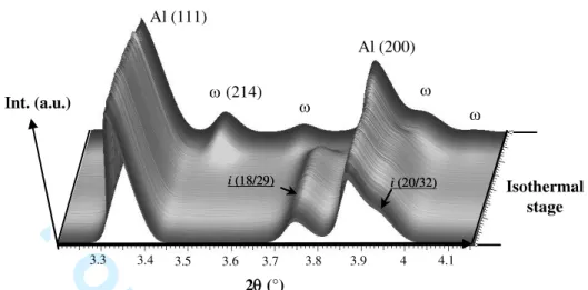
Figure 1 gives a three dimensional representation of the set of diffraction patterns acquired during the isothermal stage for a composite containing 15 vol. % of non-oxidized i-AlCuFeB particles prepared by cold isostatic pressing. At first, the sample only contains fcc aluminium and the i-AlCuFeB phase. The diffraction patterns obtained from composites containing pre-oxidized powders are similar, with no additional diffraction peaks, suggesting that the oxide layer is either amorphous or poorly crystallized and very thin. The phase transformation i-AlCuFeB L I-Al7Cu2Fe is clearly observed in Figure 1, with the
progressive disappearance of the (18/29) and (20/32) peaks of the i-phase and the simultaneous appearance of peaks corresponding to the I-phase. In all cases, the phase transformation starts during the isothermal stages allowing to observe the influence of the temperature on the kinetics of the I-phase formation.
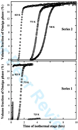
Figure 2 shows the evolution of the volume fractions of the I-phase during the transformation (i L I) for the two sets of composites prepared by cold isostatic pressing. The phase fractions are determined using the integrated intensities of the main diffraction peaks for each phase. Absolute values are estimated thanks to calibration using the known initial volume fractions for the Al/(i-AlCuFe) composites or by using theoretical intensities calculated from structural data for the Al/(I-AlCuFe) composites resulting from the thermal treatment. The volume fraction fv for each phase can be estimated using the following formulas: ) 214 ( 2 ) 29 / 18 ( 1 ) 111 ( ) 111 (
I
K
I
K
I
I
fv
i Al Al Al+
+
=
) 111 ( 4 ) 214 ( 3 ) 29 / 18 ( ) 29 / 18 ( Al i i iI
K
I
K
I
I
fv
+
+
=
) 111 ( 6 ) 29 / 18 ( 5 ) 214 ( ) 214 ( Al iK
I
I
K
I
I
fv
+
+
=
(1) 3 4 5 6 7 8 9 10 11 12 13 14 15 16 17 18 19 20 21 22 23 24 25 26 27 28 29 30 31 32 33 34 35 36 37 38 39 40 41 42 43 44 45 46 47 48 49 50 51 52 53 54 55 56 57 58 59 60For Peer Review Only
where fvAl + fvi+ fv = 1, IAl(111), Ii(18/29) and I (214) are the integrated intensities of the Al (111),
i-phase (18/29) and -phase (214) peaks respectively, Kj(j = 1,…,6) are constants calculated
using known initial volume fractions for Al/(i-AlCuFe) composites or by using theoretical intensities calculated from structural data for the Al/(I-AlCuFe) composite (Table 1).
Figure 2 shows that the formation of the -phase is much faster for composites containing non-oxidized AlCuFeB particles (series 1) rather than pre-oxidized particles (series 2). In the former case, the iLI transformation is almost completed after 0.3 hour at 823 K and
after 2 hours at 773 K (a temperature of 723 K was not sufficient to induce the transformation). For pre-oxidized particles, the kinetics of the phase transformation is slower, even at high temperature, and the time to complete the transformation is approximately 3, 5 and 7 hours at 823, 773 and 748 K, respectively. This means that Al diffusion is reduced by the oxide barrier, opening a window to form (Al/(AlCuFeB)p) composites containing only Al and the icosahedral phase by sintering up to 823 K. Figure 2 also shows that the incubation time of the transformation, determined by the appearance of the first diffraction peak of the I phase, increases when the temperature decreases and when the AlCuFeB particles are oxidized .
3.1.2 Formation of the $-Al7Cu2Fe phase
The isothermal mechanism of the phase transformation can be analyzed on the basis of the Johnson–Mehl–Avrami (JMA) law [16]:
) ) ( exp( 1 ) (t kt n fv = (2)
where fv(t) is the transformed volume fraction of the I phase, t is the real time of the transformation, which is determined as the total time minus the incubation time, k is the crystallization rate constant, and n is the Avrami exponent reflecting the nature and geometry of the mechanisms of nucleation and growth during phase transformation. The value of n can be determined using the following equation:
{
ln(1 ( ))}
ln( ) ln( )ln fv t =n k +n t (3)
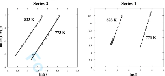
and plotting ln{-ln(1-fv(t))} versus ln(t) for different temperatures allows to derive the exponent n. Figure 3 shows the JMA plots for the two series of composites over the range of transformed volume fraction between 10 and 90 vol. %. The Avrami exponent takes a value of about 2.25 ± 0.25 (Table 2) for both series, independently of the temperature and of the pre-treatment. Based on the work of Christian [16], the n exponent of the i L I transformation is consistent with a three-dimensional (3D) diffusion-controlled growth with decreasing nucleation rate. The growth of the first I nuclei formed is faster than nucleation
3 4 5 6 7 8 9 10 11 12 13 14 15 16 17 18 19 20 21 22 23 24 25 26 27 28 29 30 31 32 33 34 35 36 37 38 39 40 41 42 43 44 45 46 47 48 49 50 51 52 53 54 55 56 57 58 59 60
For Peer Review Only
and growth of subsequent I nuclei. The initial stage of the transformation could be controlled by a grain edge nucleation of the I phase. In this case, nucleation could occur at the interface of two i crystallites and the amorphous oxide layer.
The growth rate of the volume fraction of the I phase can be determined by differentiation of the JMA equation:
) ) ( exp( . . ) ( )) ( ( nkntn 1 kt n t d t fv d = (4) The growth rates for each series are listed in Table 2. As expected, the rates increase for non-oxidized i particles. For comparison, growth rates of the 2nd series are 2 times larger than for the first series at 773 K and 8 times larger at 823 K. These results support further the fact that the oxide barrier is effective to prevent formation of the I phase.
3.2. Friction, hardness and compressive behaviours of bulk composites
Al/(AlCuFeB)p composites were prepared by sintering, containing different particle volume fractions and using different pre-oxidized treatments of the AlCuFeB particles, either to prevent or to promote the formation of the I-phase. The fraction of the I-phase after sintering decreases with increasing oxidation time and almost vanishes for 100 hours of oxidation pre-treatment in air.
3.2.1 Friction and hardness behaviours
Using this set of composites, the influence of the i-phase on friction and hardness was tested. Table 3 summarizes the main characteristics of the different samples. Figure 4 shows the variation of the work of the friction force, calculated by integrating each friction curve over the first five meters of sliding. The work of the friction force decreases with increasing volume fraction of AlCuFeB particles, confirming our previous observation [10]. The Brinell hardness also increases with increasing volume fraction of AlCuFeB particles. The presence of the i-phase in Al/(AlCuFeB)p composites improves the friction and hardness properties less significantly than when the -phase is present. This result may be explained by the embrittlement of the interface between the aluminium matrix and the icosahedral particles due to presence of the oxide layer. SEM investigations of the worn surface of the composites and indenters show that the AlCuFeB particles and counterpart balls are covered by a transferred layer which is made up primarily of aluminium and oxygen (not shown here). For composites containing 60 vol. % of AlCuFeB particles, the work of the friction force is divided by three and the hardness increased by a factor of 6 compared to the properties of the aluminium matrix. 3 4 5 6 7 8 9 10 11 12 13 14 15 16 17 18 19 20 21 22 23 24 25 26 27 28 29 30 31 32 33 34 35 36 37 38 39 40 41 42 43 44 45 46 47 48 49 50 51 52 53 54 55 56 57 58 59 60
For Peer Review Only
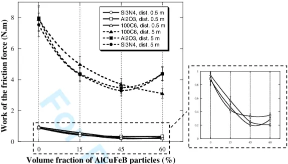
Different types of indenters (100Cr6 hard steel, Al2O3and Si3N4) have been used with
the hope to avoid aluminium transfer during sliding. Alumina is an inert oxide and thus could limit material transfer. Silicon nitride is likely to react with aluminium and could modify the nature of the pin/composite interface by forming compounds of AlN or AlSi type. However, all the tests carried out presented a similar behaviour to those obtained with the 100Cr6 indenters within experimental accuracy, as shown in Figure 5. This can be explained by the high contact pressures in our experimental conditions (500 MPa), producing severe plastic deformation and coating of the indenter by Al transferred from the matrix. Therefore, the actual sliding body is no more hard steel or ceramic but essentially Al. Only at the beginning of the friction experiment does the nature of the sliding bodies have an influence on friction, before material transfer occurs. We observe that the friction coefficient ranges from 0.1 to 0.3 at the beginning of the sliding, depending on the composites, and then reaches a common value of about 0.6 after 5 m of sliding, independently of the sample as a result of material transfer.
3.2.2 Compressive behaviour
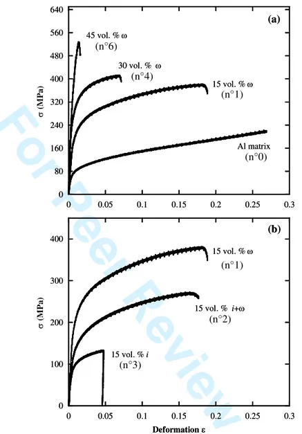
Compressive tests have been performed on the different samples listed in Table 4. Stress-strain curves obtained from room temperature compression tests are presented in Fig. 6. Data in Fig. 6a are for composites containing only the I-phase at different volume fractions whereas data in Fig. 6b are for composites containing 15 vol. % of pre-oxidized AlCuFeB particles. Measurements of yield strength byield of the different samples are shown in Table 5.
The yield point byield was defined as the stress at 0.2% of plastic deformation. Although
differences are observed in compression strain and strength, all composites have a similar compressive behaviour. After exceeding the yield stress, the stress increases with increasing deformation up to the ultimate compressive strength. A significant increase of the yield stress byield and the hardness was achieved by incorporating AlCuFeB particles into the pure
aluminium matrix. High yield strength of 405 MPa was obtained for the composite containing a volume fraction of particles of 45 %. Relative to the properties of the matrix, it corresponds to an increase of the yield stress ( b0.2) by 300 MPa (290 %) and of the hardness by 143 HB
(350 %), respectively, as shown in Table 5. However, in the same time, the ductility of the composite is reduced. For comparison, Al composites reinforced with 40 vol. % of SiC particles (10-21µm) have a b0.2 of about 150 MPa [17]. As already mentioned by several
studies [5-9, 18], the I phase can be used as an effective reinforcement compared to commercial Al composites. Contrary to Al/(SiC)p composites the formation of the I phase induces compressive residual stresses in the Al matrix associated with an unusual strengthening, as reported by Tang et al. [15, 17].
3 4 5 6 7 8 9 10 11 12 13 14 15 16 17 18 19 20 21 22 23 24 25 26 27 28 29 30 31 32 33 34 35 36 37 38 39 40 41 42 43 44 45 46 47 48 49 50 51 52 53 54 55 56 57 58 59 60
For Peer Review Only
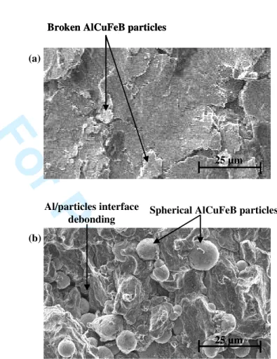
In the case of pre-oxidized AlCuFeB particles, the mechanical resistance and ductility are poorer although the i phase is preserved (Fig. 6b and Table 5). This is counterintuitive, since the mechanical properties of the i phase are better than those of the I phase and therefore improved properties of the composite should result as reported by Fleury et al. [9] and Tsai et al. [4]. The lower mechanical properties observed in our case can only be attributed to the embrittlement of the Al/particles interface due to the oxide layer. These results are consistent with several recent studies by Tang et al. [6-8] demonstrating the importance of the oxide layer thickness on the mechanical properties of similar composite materials. The embrittlement of the Al/particles interface is highlighted by observing the fracture surfaces of composite samples, either reinforced by i-AlCuFe particles or by I-AlCuFe particles. Figure 7 shows that fracture occurs at the Al/particles interface when particles have been oxidized. When non-oxidized particles are used, the fracture surface propagates through the reinforcement particles (Fig. 7(a)). Consequently, the formation of the I phase enhances the bonding strength between the matrix and the particles due to inter-particle diffusion during the solid state sintering process [ 5-9, 18].
4. Conclusions
Oxidation pre-treatment of the icosahedral quasicrystalline particles allowed us to reduce significantly the kinetics of Al diffusion from the matrix to the quasicrystalline particles for temperatures up to 823 K. Consequently, composites made of i-Al59Cu25.5Fe12.5B3
particles dispersed in a pure aluminium matrix with different volume fractions could be prepared by solid state sintering with low uniaxial pressure. This positive result is however weakened because the oxide layer causes embrittlement of the Al/i-AlCuFeB interfaces. Friction and mechanical properties of the composites have been measured for different compositions. A significant decrease of the work of the friction force and an increase of the mechanical properties is observed with increasing volume fraction of AlCuFeB particles, up to 60 vol. %. The best mechanical properties are obtained when the reinforcement particles are totally transformed into tetragonal I-phase due to enhanced inter-particle bonding.
Acknowledgements
We would like to thank the staff of the ID15B beamline at the European Synchrotron Radiation Facility for technical assistance. We are grateful to S. Raffy (St Gobain) for the provision of quasicrystalline powders and to P. Delcroix for preparing samples by cold isostatic pressing. Help in SEM and compression test experiments by D. Bonina (LSG2M,
3 4 5 6 7 8 9 10 11 12 13 14 15 16 17 18 19 20 21 22 23 24 25 26 27 28 29 30 31 32 33 34 35 36 37 38 39 40 41 42 43 44 45 46 47 48 49 50 51 52 53 54 55 56 57 58 59 60
For Peer Review Only
Nancy) and O. Ferry (LPM, Nancy) is greatly acknowledged. This work was supported by the ADEME agency under contract n° 03 66 033.
References
[1] J.M. Dubois, S.S. Kang and J. von Stebut, J. Mater. Sci. Lett. 10 (1991), 537.
[2] J.M. Dubois, P. Plaindoux, E. Belin-Ferré, N. Tamura, D.J. Sordelet, in: S. Takeuchi and T. Fujiwara, Editors, Proceedings of the Sixth International Conference on Quasicrystals, ICQ6, World Scientific, Singapore, (1997), 733.
[3] J.M. Dubois, S.S. Kang and Y. Massiani, J. Non-Cryst. Solids 153&154 (1993), 443. [4] A.P. Tsai, K. Aoki, A. Inoue and T. Masumoto, J. Mater. Res. 8, 1 (1993), 5.
[5] F. Tang, I.E. Anderson and S.B. Biner, J. of Light Metals 2, (2002), 201. [6] F. Tang, I.E. Anderson and S.B. Biner, Mat. Sci. Eng. A 363, (2003), 20.
[7] F. Tang, I.E. Anderson, T. Gnaupel-Herold and H. Prask, Mat. Sci. Eng. A 383, (2004), 362.
[8] F. Tang, T. Gnaupel-Herold, H. Prask and I.E. Anderson, Mat. Sci. Eng. A 399, (2005), 99.
[9] E. Fleury, S.M. Lee, G. Choi, W.T. Kim, D.H. Kim, J. Mater. Sci. 36 (2001), 963.
[10] S. Kenzari,P. Weisbecker, G. Geandier, V. Fournée and J.M. Dubois, Phil. Mag. 86 , 3-5, (2006), 287.
[11] S.S. Kang and J.M. Dubois, Phil. Mag. A 66 (1) (1992), 151.
[12] P. Brunet, L.M. Zhang, D.J. Sordelet, M. Besser and J.M. Dubois, Mater. Sci. Eng. A 294 (2000), 74.
[13] J.M. Dubois, P. Archambault, L. Bresson and P. Cathonnet, French Patent N° 9 602 224 (1996).
[14] G. Bonhomme, M. LeMieux, P. Weisbecker, V.V. Tsukruk and J.M. Dubois, J. Non-Cryst. Solids 334&335 (2004), 532.
[15] P. Weisbecker, G. Bonhomme, G. Bott and J.M. Dubois, J. Non-Cryst. Solids 351 (2005), 1630.
[16] J.W. Christian, The theory of transformations in metals and alloys, Pergamon, London (1965).
[17] D.L. Mcdanels, Metal. Trans. A 16, (1985), 1105.
[18] S.M. Lee, J.H. Jung, E. Fleury, W.T. Kim et D.H. Kim, Mat. Sci. Eng. A 294-296, (2000), 99. 3 4 5 6 7 8 9 10 11 12 13 14 15 16 17 18 19 20 21 22 23 24 25 26 27 28 29 30 31 32 33 34 35 36 37 38 39 40 41 42 43 44 45 46 47 48 49 50 51 52 53 54 55 56 57 58 59 60
For Peer Review Only
2 (°) (214) Al (111) Al (200) i (18/29) i (18/29) i (20/32)i (20/32) 3.3 3.4 3.5 3.6 3.7 3.8 3.9 4 4.1 Isothermal stage Int. (a.u.) Table 1Kj values for volume fraction calculations.
K1 K2* K3* K4 K5* K6*
Kj
0.975 1.199 1.025 1.229 0.814 0.834
*Constants calculated using theoretical intensities calculated from structural data for the Al 50 vol. % + 50 vol. % composite.
Figure 1. 3D representation of diffraction patterns obtained during an isothermal stage at 773 K. 3 4 5 6 7 8 9 10 11 12 13 14 15 16 17 18 19 20 21 22 23 24 25 26 27 28 29 30 31 32 33 34 35 36 37 38 39 40 41 42 43 44 45 46 47 48 49 50 51 52 53 54 55 56 57 58 59 60
For Peer Review Only
0 2 4 6 8 10 12 14 16 773 K 823 K 748 K Series 2 V ol um e fr ac ti on o f O m ég a p h as e (% ) 0 2 4 6 8 10 12 14 16 0 2 4 6 8 10 823 K 773 K 723 K V ol u m e fr ac ti on o f O m ég a ph as e (% )Time of isothermal stage (hrs) Series 1 0 2 4 6 8 10 12 14 16 773 K 823 K 748 K Series 2 V ol um e fr ac ti on o f O m ég a p h as e (% ) 0 2 4 6 8 10 12 14 16 0 2 4 6 8 10 823 K 773 K 723 K V ol u m e fr ac ti on o f O m ég a ph as e (% )
Time of isothermal stage (hrs) Series 1
Figure 2. Top: Volume fraction of -phase for the
composites containing i-particles oxidized in air for 60 minutes as a function of time and isothermal temperatures. Bottom: volume fraction of -phase for the composites containing i-particles annealed in vacuum for 60 minutes as a function of time and isothermal temperatures. 3 4 5 6 7 8 9 10 11 12 13 14 15 16 17 18 19 20 21 22 23 24 25 26 27 28 29 30 31 32 33 34 35 36 37 38 39 40 41 42 43 44 45 46 47 48 49 50 51 52 53 54 55 56 57 58 59 60
For Peer Review Only
- 3 2.5 - 2 1.5 - 1 - 0.5 0 0.5 1 Series 2 Series 1 - 3 2 - 2 1 - 1 - 0 0 0 1 3 4 5 6 7 8 9 823 K 823 K 773 K 773 K ln(t) ln(t) -3 -2 -1 0 1 6 6.5 7 7.5 8 8.5 9 9.5 ln (-ln (1 -f v( t) )) 2 3 4 5 6 7 8 0 50 100 150 200 250 300 350 400 1 2 3 4 5 6 W or k of t he f ri ct io n f or ce ( N .m ) B rin ell h ar d ne ss (H B ) Samples Table 2Comparison of the main characteristic data of the phase formation.
Tisothermal (K) n k (sec-1) d(fv )/d(t) max (min-1)
773 2 4.8392.10-4 0.029753 Series 1 823 2.5 5.6201.10-4 0.28423 773 2.3 2.6803.10-4 0.015361 Series 2 823 2.2 6.3634.10-4 0.035102 Table 3
Summary of the XRD analyses of samples.
Composite N° AlCuFeBVol. % Pre-TreatmentOxidation before sinteringXRD after sinteringXRD
1 0 - Al Al 2 15 in vacuum Al + i Al + 3 15 in air for 100h Al + i Al + i 4 30 in vacuum Al + i Al + 5 30 in air for 75h Al + i Al + i + 6 60 in vacuum Al + i Al +
Figure 4. Brinell hardness and work of the friction force
of the various samples listed in Table 3. Lines are only
Figure 3. JMA plots for the two series of Al/(AlCuFeB)p composites. The slope of each line takes value
of about 2.25 ± 0.25. 3 4 5 6 7 8 9 10 11 12 13 14 15 16 17 18 19 20 21 22 23 24 25 26 27 28 29 30 31 32 33 34 35 36 37 38 39 40 41 42 43 44 45 46 47 48 49 50 51 52 53 54 55 56 57 58 59 60
For Peer Review Only
02 4 6
8 Si3N4, dist. 0.5 mAl2O3, dist. 0.5 m 100C6, dist. 0.5 m 100C6, dist. 5 m Al2O3, dist. 5 m Si3N4, dist. 5 m
Volume fraction of AlCuFeB particles (%)
W or k of t he f ri ct io n fo rc e (N .m ) 0 15 45 60 0 0.2 0.4 0.6 0.8 1 0 15 45 60 Table 4
Summary of the XRD analyses of samples.
Composite N° Vol.% AlCuFeB Pre-treatmentsOxidation before sinteringXRD after sinteringXRD
0 0 - Al Al 1 15 - Al + i+ Al + 2 15 in air for 10h Al + i Al + i + 3 15 in air for 100h Al + i Al + i 4 30 - Al + i+ Al + 5 30 75h Al + i Al + i + 6 45 - Al + i+ Al + Table 5
Mechanical properties of samples listed in Table 4.
Composite N° yield (MPa)
± 10 % Hardness (HB) Increase of Hardness Increase of yield ( 0.2)
compared to the Al matrix
0 104 41± 2 - -1 159 67 ± 3 26 MPa , 63 % 55 MPa , 53 % 2 127 50 ± 3 9 MPa , 21 % 23 MPa , 22 % 3 72 40 ± 2 -1 MPa , -3 % -30 MPa , -31 % 4 251 100 ± 5 59 MPa , 143 % 147 MPa, 141 % 5 183 70 ± 4 29 MPa , 70 % 79 MPa , 76 % 6 405 184 ± 18 143 MPa , 348 % 301 MPa , 289 %
Note: All the indicated values correspond to an average value of at least 2 samples.
Figure 5. Dependencies of the work of the friction force with the volume fraction of AlCuFeB
particles and the sliding distance for different indenters.
3 4 5 6 7 8 9 10 11 12 13 14 15 16 17 18 19 20 21 22 23 24 25 26 27 28 29 30 31 32 33 34 35 36 37 38 39 40 41 42 43 44 45 46 47 48 49 50 51 52 53 54 55 56 57 58 59 60
For Peer Review Only
Figure 6. Comparison of the stress-strain curves of the
Al/(AlCuFeB)p composites prepared with particles containing only the -phase at different volume fractions (a) containing 15 vol. % of pre-oxidized AlCuFeB particles (b). Composite numbers listed in Table 4 are given.
0 80 160 240 320 400 480 560 640 0 0.05 0.1 0.15 0.2 0.25 0.3 (M P a) 45 vol. % 30 vol. % 15 vol. % Al matrix 0 100 200 300 400 0 0.05 0.1 0.15 0.2 0.25 0.3 (M P a) Deformation 15 vol. % i 15 vol. % i+ 15 vol. % (a) (b) 0 80 160 240 320 400 480 560 640 0 0.05 0.1 0.15 0.2 0.25 0.3 (M P a) 45 vol. % 30 vol. % 15 vol. % Al matrix 0 100 200 300 400 0 0.05 0.1 0.15 0.2 0.25 0.3 (M P a) Deformation 15 vol. % i 15 vol. % i+ 15 vol. % (a) (b) (n°6) (n°4) (n°1) (n°0) (n°1) (n°2) (n°3) 3 4 5 6 7 8 9 10 11 12 13 14 15 16 17 18 19 20 21 22 23 24 25 26 27 28 29 30 31 32 33 34 35 36 37 38 39 40 41 42 43 44 45 46 47 48 49 50 51 52 53 54 55 56 57 58 59 60
For Peer Review Only
25 µm 25 µm 25 µm Al/particles interface debonding 25 µm Broken AlCuFeB particles25 µm 25 µm Broken AlCuFeB particles
(a)
(b)
Spherical AlCuFeB particles
Figure 7. Representative fracture surfaces of (a) composite
samples containing the phase and (b) the i phase.
3 4 5 6 7 8 9 10 11 12 13 14 15 16 17 18 19 20 21 22 23 24 25 26 27 28 29 30 31 32 33 34 35 36 37 38 39 40 41 42 43 44 45 46 47 48 49 50 51 52 53 54 55 56 57 58 59 60