Nom de la revue. Volume X – n° X/2002, pages 1 à X
brittle formation
Frédéric Collin
1,4− Xiang Ling Li
2– René Chambon
3– Robert
Charlier
11
Université de Liège
Institut de Génie Civil et de Mécanique Chemin des Chevreuils 1, 4000 Liège Sart Tilman, Belgique
f.collin@ulg.ac.be
2
SCK-CEN, Mol, Belgium
3
Laboratoire 3S, CNRS-UJF-INPG, Grenoble, France
4
Chargé de Recherches, Fonds National Belge de la Recherche Scientifique
RÉSUMÉ. Cet article s’intéresse aux effets de couplages pouvant apparaître entre le problème
mécanique et la diffusion d’eau lors du creusement d’une excavation, en relation avec la problématique du stockage de déchets nucléaires. Les couplages hydromécaniques sont tout d’abord mis en évidence. Ensuite, l’effet de la prise en compte de la variabilité de la perméabilité avec l’endommagement sont présentés. Enfin, différents types de condition limite du problème écoulement sont considérés et leur influence sur la convergence de la galerie et sur la localisation des déformations est étudiée.
ABSTRACT. This paper is concerned with the coupling effects existing between the mechanical
problem and the water diffusion process during an excavation, in relation with the nuclear waste disposal concepts. The hydromechanical coupling effects are first evidenced. Then, the permeability variation with damage is studied. Finally, different kind of flow boundary condition are considered. Their influence on the cavity convergence is highlighted and their effect on strain localisation process as well.
MOTS-CLÉS : couplages hydromécaniques, localisation des déformations, enfouissement de
déchets, condition limite.
KEYWORDS: hydromechanical coupling, strain localisation, underground storage, boundary
1. Introduction
One solution nowadays proposed for long term nuclear waste is the realization of waste repositories in deep geological low permeability layers: the Boom Clay formation in Belgium, clay-stone formation in France and granite and claystone formations in Switzerland for example. These geological layers ensure a natural protection against an eventual migration of radionuclide to the human activity areas. Underground waste disposals are thus going to be constructed by building a network of wells and galleries in the host formation. An important aspect of this problem is the necessity to ensure that gallery excavation does not damage the host formation. Indeed if some fracturation processes appear, they will constitute preferential paths for pollutant migration like radionuclide. The tunnelling method should then minimize the damaged zone (EDZ) around the excavation. The mechanical behaviour of the host formation is usually brittle and the constitutive laws usually used to reproduce their behaviour are damaged models or strain-softening models. Such kind of models allows to reproduce the progressive decrease of material strength during testing; consequently, they predict also strain localisation, which is observed in-situ ([MER 04]).
The final objective of the GDR-Momas benchmark is the evaluation of the relevance of the numerical codes used by the participants to model the different proposed tests with the same constitutive equations. The different scientific teams participating and the benchmark contents are described in [CHA 05]. The modelling focuses on the coupling between mechanical behaviour of the host formation and the hydraulic diffusion (in saturated/unsaturated conditions) during the excavation process. In the following, we present first the constitutive mechanical law and the diffusion model prescribed by the benchmark proposal. Two different simulations are then presented with an isotropic and anisotropic initial stress state respectively. For each case, the influence of the flow boundary condition is highlighted: imposed pore pressure, dripping condition or imposed relative humidity (RH) condition. Moreover, due to the damaged process, the permeability increases, which influences strongly cavity convergence in these coupled simulations.
2. Benchmark exercises
This coupled modelling is a benchmark exercise proposed by the GDR-Momas and organized by EDF-CEA ([CHA 05]). The aim of this exercise is the study of the excavation process with a very simple strain-softening constitutive law in order to better understand the evolution of the EDZ in a coupled problem. The main phenomena appearing during tunnelling are taken into account: the progressive decrease of material strength, the increase of the permeability and the strain localisation. Physical phenomena like thermal or creep effects are out of the scope of this benchmark exercise.
2.1. Description of the constitutive model
The proposed constitutive law is an elasto-plastic strain-softening model. The yield criterion is a Drucker-Prager model given by the following equation:
* 3 3 0 2 tan c F IIσ m Iσ φ ⎛ ⎞ ≡ + ⎜ − ⎟= ⎝ ⎠ [1]
where IIσ∗ is the second deviatoric stress invariant, Iσ is the first stress invariant,
φ is the friction angle, parameter m is a function of φ: m = 2 sin(φ)/(3-sin(φ)), the
cohesion c= c0 f(γ p) is the softening variable, c0 is the initial cohesion and γ p is the
equivalent deviatoric plastic deformation.
The evolution of the cohesion is related to the equivalent plastic deformation through the following relationship:
2 2 ( ) 1 (1 ) 0 p p p p R p R p p R f if si γ γ α γ γ γ α γ γ ⎛ ⎞ = − −⎜ ⎟ < < ⎝ ⎠ = ≥ [2] 0 1 2 3 4 5 6 7 8 9 10 0.00 0.20 0.40 0.60 0.80 1.00 EPS1 [%] q [ MPa ] (a) 0.00 0.20 0.40 0.60 0.80 1.00 1.20 0.00 0.20 0.40 0.60 0.80 1.00 1.20 1.40 1.60 γp [%] Cohe s ion [MP a ]_ (b)
Figure 1. Drained triaxial modeling: Evolution of deviatoric stress and cohesion
A drained triaxial test has been modelled with this constitutive relationship and the results are presented on Figure 1-a,b. The deviatoric stress (noted q) is first increasing during the elastic phase as a function of the axial strain (noted EPS1). When the plastic criterion is reached, the strength of the material progressively decreases as the strain-softening takes place. This softening is evidenced on Figure 1-b that shows the evolution of the cohesion as a function of the deviatoric strain.
This simulation and the further ones have been performed with the parameters values defined in Table 1.
Name Value Unit
E0 Young modulus 5800 MPa
ν0 Poisson ratio 0.3 -
c0 Initial cohesion 1 MPa
φ Friction angle 25 Degree
α Relative residual cohesion 0.01 -
p R
γ
Deviatoric strain threshold 0.015 -Table 1: Parameters used in the simulations (Mechanical model)
The water flows in the medium are predicted through the generalized Darcy’s law: int. ( ) . . ( ) w w w w k f grad p ρ g grad y µ ⎡ ⎤ = − ⎣ + ⎦ [3]
In unsaturated brittle geomaterials, the intrinsic permeability is a function of the saturation degree and the damage process. The following expression is used in the simulations:
int ,. , . int
sat r n r w
k =k k k [4]
where kr,n et kr,w are given by the following relationship in the frame of the
benchmark proposal:
(
)
1.176 1 2.429 , 1 , 1 r w r w k S − − ⎡ ⎤ = +⎢ − ⎥ ⎣ ⎦ [5] , 0 12 3 2 , 0 0 6 2 , 0 1 0 1 2.10 ( ) 0 10 1 2.10 10 r n r n r n k if n n k n n if n n k if n n − − = − < = + − < − < = + − > [6]As far as unsaturated conditions are concerned, the following expression of the retention curve is used, valid if the suction s is positive:
0.412 1 1 0.412 , 1 7 10 r w s S − − ⎡ ⎛ ⎞ ⎤ ⎢ ⎥ = + ⎜⎢ ⎝ ⎟⎠ ⎥ ⎣ ⎦ [7]
The following simulations have been performed with the parameters values defined in Table 2.
Name Value Unit
n0 Initial porosity 0.15 -
b Biot’s coefficient 0.8 -
Kw Incompressibility modulus 2000 MPa
int
sat
k Intrinsic permeability 10-19 m²
ρw Water density 1000 Kg/m³
Table 2: Parameters used in the simulations (Flow model)
The FE code Lagamine is used for the benchmark modelling. Details on the implementation of such coupled models in the FE code can be found in [LI 00, COL 02] ; the description of the FE code (general formulation, resolution technique) is presented in [CHA 87].
2.2. Description of the problem
A cylindrical unsupported cavity of 3 m diameter is located in an homogeneous low permeability formation. The excavation process is 1.5 Ms (around 17 days) long and is modelled by decreasing the initial total stress and pore pressure towards zero. Two main cases have been considered depending on the initial stress state. A first case considers an isotropic stress state, which allows a one dimensional axisymetrical modelling: ' ' ' 7.74 4.7 xx zz yy w MPa p MPa σ =σ =σ = − =
A second case considers an initial anisotropic stress state (with the same pore pressure), which needs a bidimensional plane strain modelling:
' ' ' 7.74 11.64 xx zz yy MPa MPa σ σ σ = = − = −
In both cases, two steps are considered: first the excavation process (duration T = 1.5 Ms) and a second phase during which the radial convergence of the cavity evolves due to the water diffusion process. The final modelling time is 300 Ms (about 9.5 years). At the external boundaries of our model, the initial conditions are assumed to be preserved in terms of total stress and pore pressure. This supposes that the external boundaries are far enough from the cavity. In the modelling, they are located at a radial distance seven times the cavity radius.
at r=3m ' 0 0 1 4.7 1 0 w w xx yy w for t T t bp T t p T for t T p σ σ σ σ σ ≤ ≤ ⎧ ⎪ ⎛ ⎞ ⎪ = − = ⎜ − ⎟ ⎪ ⎝ ⎠ ⎪⎪ ⎛ ⎞ ⎨ = − ⎜ ⎟ ⎪ ⎝ ⎠ ⎪ > ⎪ ⎪ = = = ⎪⎩ and at r=∝ 0 4.7 w p MPa σ σ ⎧ = ⎨ = ⎩
3. Isotropic stress state: Axisymetric modelling
In this unidimensional axisymetrical modelling, we present first the case where the permeability is not evolving with porosity changes (Referred as case 1.1). It allows us to evidence the influence of the flow boundary condition and the permeability increase. -4 -3 -2 -1 0 1 2 3 4 5 6 2 4 6 8 10 12 14 16 18 20 Radial distance [m] Pore pre s s u re [ M Pa ]_ t = 1.5 E6 s t = 5.0 E6 s t = 50 E6 s t = 300 E6 s (a) -20 -18 -16 -14 -12 -10 -8 -6 -4 -2 0 0 2 4 6 8 10 12 14 16 18 20 Radial distance [m] Radi al di spl acem ent [cm ] t = 1.5 E6 s t = 5.0 E6 s t = 50 E6 s t = 300 E6 s (b)
Figure 2. Pore pressure and displacement curve during coupled excavation
In Figure 2-(a), we see that the pore pressure remains (at the cavity nodes) at the atmospheric pressure after the excavation phase. Due to the hydro-mechanical coupling (dilatancy effect), a pore pressure decrease is observed in the damaged zone, which implies an ‘numerical’ injection of water into the formation. Moreover, Figure 2-(b) shows that the radial displacement is equal to 1.26 cm at the end of the excavation and reaches 19.3 cm after 300 Ms. The coupling effects between the water diffusion and the mechanical process are thus important.
3.1. Influence of hydric boundary condition
A more realistic condition (for the flow problem) is a dripping boundary condition: a water outflow can be created only if the pore pressure in the formation
is higher than the atmospheric pressure (Unilateral flow condition). This case will be referred as case 1.2 in the following. On the other hand, for long-term predictions, one can assume an equilibrium between the pore pressure at the tunnel and the relative humidity of the cavity atmosphere. Indeed, this relative humidity can be controlled in waste disposal. A third case (Case 1.3) is then considered, where a negative pressure of –5 MPa is imposed as boundary condition.
Figure 3 shows the resulting pore pressure distribution for the two latter cases. In Case 1.2, the pore pressure becomes negative near the cavity at the end of the excavation. Then pore pressure increases progressively. In case 1.3, the results is similar at the end of the excavation. However, after this first phase, the pore pressure remains negative as it is imposed by the boundary condition and the suction diffuses in the formation.
-4 -3 -2 -1 0 1 2 3 4 5 6 2 4 6 8 10 12 14 16 18 2 Radial coordinate [m] P o re pr essur e [ M P a ] t = 1.5 E6 s t = 5.0 E6 s t = 50 E6 s t = 300 E6 s (a) Case 1.2 -6 -4 -2 0 2 4 6 2 4 6 8 10 12 14 16 18 20 Radial coordinate [m] Por e pr essur e [ M Pa] t = 1.5 E6 s t = 5.0 E6 s t = 50 E6 s t = 300 E6 s (b) Case 1.3 Figure 3. Pore pressure distribution in case 1.2 and case 1.3
These pore pressure distributions have a direct influence on the convergence predicted. Table 3 presents the results for the three cases. At the end of the excavation, the convergences are more or less the same. But as far as the long-term response is concerned, the predicted displacements are rather different. Indeed in case 1.3, the remaining suction near the tunnel ensures an additional strength and limits the material deformations. The case 1.3 condition predicts a rather narrow EDZ in comparison with the two other ones.
Case 1.1 Case 1.2 Case 1.3
t = 1,5 Ms 1,26 cm 1,03 cm 1,52 cm
t = 300 Ms 19,3 cm 7,45 cm 1,58 cm
3.2. Influence of the permeability increase
In the following simulations, the permeability is increasing as a function of the porosity (Equation 6). The three previous cases corresponding to different flow boundary conditions are considered (Case 1.4, 1.5 and 1.6).
When the pore pressure has decreased to the atmospheric pressure (Case 1.4), the simulation becomes numerically difficult. Indeed, due the increase of permeability, the pressure field is quite uniform (and equal to the atmospheric pressure) in the plastic zone. Therefore, the ‘capillary cohesion’ induced by the negative pressure of the previous case disappears. After 98% of excavation, the radial convergence of the cavity is equal to 28.6 cm (around 25 times the convergence obtained with a constant permeability).
-4 -3 -2 -1 0 1 2 3 4 5 6 2 4 6 8 10 12 14 16 18 Radial distance [m]
Pore pressure [MPa]
t = 1.5 E6 s t = 5.0 E6 s t = 50 E6 s t = 300 E6 s (a) Case 1.5 -6 -4 -2 0 2 4 6 2 4 6 8 10 12 14 16 18 20 Radial distance [m] Pore pressure [ M Pa] t = 1.5 E6 s t = 5.0 E6 s t = 50 E6 s t = 300 E6 s (b) Case 1.6 Figure 4. Pore pressure distribution in case 1.5 and case 1.6
Figure 4 shows the results for the two other boundary conditions. With a dripping condition, we see clearly the zone where the pressure field is uniform (very high permeability value). At the end of the modelling the pressure is not as negative as before and the radial convergence is higher than in the previous simulation. When the suction is imposed at the boundary, the effect of permeability increase is always positive because is allows the suction diffusing deeper into the medium. This leads to lower cavity convergence.
Case 1.4 Case 1.5 Case 1.6
t = 1,5 Ms 28,6 cm 1,04 cm 1,04 cm
t = 300 Ms - 8,23 cm 1,09 cm
4. Anisotropic stress state: plane strain modelling
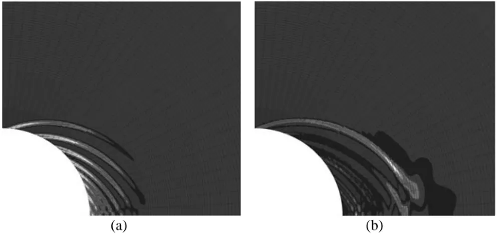
During the excavation, the behaviour of the material becomes plastic near the tunnel and permanent strains are created. The yield criterion is first met in the direction where the orthoradial stress is the major principal stress. The pore pressure distribution and the radial displacement curves are similar to the ones obtained in axisymetrical simulations. However, the difference is that shear band localization appears during the modelling. Indeed, at the end of excavation, there is no clear localization patterning even if the Rice’s criterion is met. After that step, pore pressure increases progressively (in the plastic zone) and a patterning is gradually created. Figure 5-a presents a map of equivalent strains, where the different shear bands appears clearly. A deviatoric strain intensity indicator is shown in Figure 5-b; this indicator evidences the strain activity of the shear band. One can see here that only the external shear band is active at the end of the simulation and that a chip is finally created. It is clear however that these results are mesh dependent and enhanced models are necessary for an objective post-localization modelling (See [ZER 01] for an example of excavation and [ZHA 04], [COL 05] for coupled enhanced models).
(a) (b)
Figure 5. Equivalent strain and deviatoric strain indicator for active shear band (t
= 300Ms)
When a suction of 5 MPa is applied at the cavity nodes, this decreases the radial convergence and this inhibits completely the shear band localisation. The increase of the permeability amplifies the decrease of radial displacement.
5. Conclusions
The GDR-Momas benchmark proposed to model the excavation process in a brittle formation using a coupled model. With the strain-softening constitutive model used, the coupling effects between water diffusion and the mechanical aspects are very important. The computations showed that the flow boundary condition at the cavity deeply influences the cavity convergence. The RH condition predicts the lowest radial displacement.
If one considers the permeability increase with the porosity changes, the influence of the different boundary conditions are exacerbated. If the pore pressure is imposed to the atmospheric one, the convergence is dramatically increased. At the opposite, if the suction is imposed, the radial displacement is decreased in comparison to the case with a constant permeability.
It is well known also that strain-softening models produce strain localisation and that the numerical responses suffer from a pathological mesh-dependency. Different numerical solutions are proposed to solve this problem, such as local second gradient models. But once again, the flow boundary condition influences deeply the model predictions. The imposed suction condition inhibits completely the shear band localisation. The choice of a correct/realistic boundary condition is thus a crucial task.
Acknowledgments
The authors are grateful to FNRS and UE (under RTN-DIGA project) for the help and grant they received.
5. References
[CHA 87] Charlier R., Approche unifiée de quelques problèmes non linéaires de mécanique des milieux continus par la méthode des éléments finis, Thèse de doctorat, Université de Liège, 1987.
[CHA 05] Chavant C., Fernandes R., Evaluating the reliability of hydro-mechanical
simulation : a benchmark of numerical techniques carried out by Research Group of
MoMas, 2nd International Meeting Clays in Natural & Engineered Barriers for
Radioactive Waste Confinement, Tours, 14-18 March 2005, pp 249-250.
[COL 02] Collin F., Li X.L., Radu J.P., Charlier R., Thermo-hydro-mechanical coupling in clay barriers, Engineering Geology, 64, 2002, pp. 179-193.
[COL 05] Collin F., Chambon R., Charlier R. A finite element method for poro mechanical modelling of geotechnical problems using local second gradient models, International
[LI 00] Li X.L., Comportement hydromécanique des sols fins : de l'état saturé à l'état non-saturé, PhD Thesis, University of Liège, 2000.
[MER 04] Mertens J., Bastiaens W., Dehandschutter B., Characterisation of induced discontinuities in the Boom Clay around the underground excavations (URF, Mol, Belgium), Applied Clay Science 26, pp 413– 428, 2004.
[ZER 01] Zervos A., Papanastasiou P., Vardoulakis I., Modelling of localisation and scale-effect in thick-walled cylinders with gradient elastoplasticity, Int. J. Solids and Struct. 38, 2001, pp. 5081-5095.
[ZHA 04] Zhang C, Schrefler B.A., Particular aspects of internal length scales in strain localization analysis of multiphase porous materials. Computer Methods in Applied