Improvement of HF RFID detection for small and misaligned tag
Texte intégral
Figure
Documents relatifs
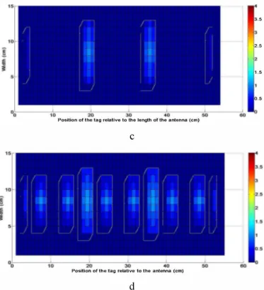
This is the perspectives of this work because the context drives us to use several resonators over the wide reader loop surface, consequently generating multiple and
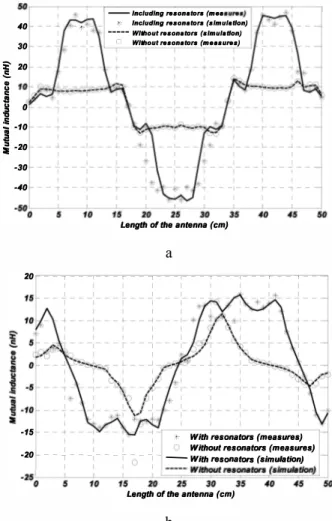
In this paper, all the equivalent impedance parameters of the system are studied according to the lateral misalignment of the tag above the reader antenna in the case of conventional
The addition of the resonator can increase the equivalent mutual inductance and mutual resistance respectively by 10 nH (from IlnH t02lnH) and 1.1 Q (from OQ to 1.1 Q)
Serializing the sub-coils in a complementary way allows an optimization of the mutual inductance value among a possible trajectory of the tags both in HM and VM. The
Improving LF Reader Antenna volume of detection for RFID token tag thanks to Identical Coaxial Loops (ICLs) and in/out-of phase multiple-loops structures.. Antoine Diet,
The addition of the resonator can increase the equivalent mutual inductance and mutual resistance respectively by 10 nH (from IlnH t02lnH) and 1.1 Q (from OQ to 1.1 Q)
Moreover, a too wide resonator would drives to a too strong coupling with the reader coil which can affect the tuning of the reader loop and penalize the detection
Finally, the measurement of the Received Signal Strength Indication (RSSI) level received by the reader antenna for different positions of a mouse phantom model in a cage is
