Science Arts & Métiers (SAM)
is an open access repository that collects the work of Arts et Métiers Institute of Technology researchers and makes it freely available over the web where possible.
This is an author-deposited version published in: https://sam.ensam.eu
Handle ID: .http://hdl.handle.net/10985/7461
To cite this version :
Guillaume FROMENTIN, Aleksandra BIERLA, Clotilde MINFRAY, Gérard POULACHON - An experimental study on the effects of lubrication in form tapping - Tribology international - Vol. 43, p.1726-1734 - 2010
An experimental study on the effects of lubrication in form
tapping
G. Fromentin (1), A. Bierla (1), C. Minfray (2), G. Poulachon (1)
(1) LaBoMaP, Arts et Metiers ParisTech Cluny, Rue porte de Paris, F-71250 Cluny, France
(2) LTDS, Ecole Centrale de Lyon, 36 avenue Guy de Collongue, F-69134 Ecully Cedex, France
Corresponding author:
Guillaume FROMENTIN, Arts et Metiers ParisTech Cluny, Rue Porte de Paris, F-71250 CLUNY, FRANCE, Tel.: + 33 385 595 330, Fax: + 33 385 595 370, email:
Abstract: This paper presents the results of a study of lubrication in form tapping and aims at a better understanding of its effect. It appears that lubrication is of paramount
importance. Oil with efficient high pressure additives can reduce considerably the torque necessary to form the thread. Lubricants reduce the tool / work material friction during the forming process and, as a consequence, the resulting strain distribution and the strain hardening of the thread are affected. This investigation includes an analysis on the effects of additives in lubricants on the temperature during tapping, enabling correlation with the appearance of chemical elements of the oil which react with the thread material and contribute to lubrication.
Key words: Metal working Fluids; Form tapping; Additives Performance Testing
Ms. Ref. No.: TRIBINT-D-09-00062
Title: An experimental study on the effects of lubrication in form tapping Tribology International
Corresponding author:
Guillaume FROMENTIN, Arts et Metiers ParisTech Cluny, Rue Porte de Paris, F-71250 CLUNY, FRANCE, Tel.: + 33 385 595 330, Fax: + 33 385 595 370,
email: [email protected]
Answer to reviewers:
Reviewers comments were taken into account and the modifications incorporated in the article.
Nevertheless one remark from 1st review was not understood. Our study duly shows that
results from tapping test and metallurgical analysis are coherent. The higher the tapping torque is the more strain hardening is appeared. Effectively it also shows that sulphur percentage on thread surface, analyzed by EDS, cannot be correlated to MFW friction reducing performance. It is understandable because this analysis only characterized chemical composition of tribological film. Then we complete our study with introducing XPS analysis in order to debate on chemical compounds of sulphured layer (sulphide or sulphate). Two new authors have also been added.
I would like to mention that, concerning the form tapping test, it allow discriminating MFW which cannot be by cut tapping.
About “formation torque”, it is named like this because is the torque needed for the thread formation. I think if we named it “forming torque”, it may be confused with tapping torque in form tapping.
The conclusion was also modified for more details.
I must acknowledge the painstaking efforts of the reviewers for the reviewing the article. I thank them for improving the understanding of the paper. I think the additions and modifications made in the article address all issues raised by the esteemed reviewers.
1 2 3 4 5 6 7 8 9 10 11 12 13 14 15 16 17 18 19 20 21 22 23 24 25 26 27 28 29 30 31 32 33 34 35 36 37 38 39 40 41 42 43 44 45 46 47 48 49 50 51 52 53 54 55 56 57
An experimental study on the effects of lubrication in form
tapping
G. Fromentin (1), A. Bierla (1), C. Minfray (2), G. Poulachon (1)
(1) LaBoMaP, Arts et Metiers ParisTech Cluny, Rue porte de Paris, F-71250 Cluny, France
(2) LTDS, Ecole Centrale de Lyon, 36 avenue Guy de Collongue, F-69134 Ecully Cedex, France
Corresponding author:
Guillaume FROMENTIN, Arts et Metiers ParisTech Cluny, Rue Porte de Paris, F-71250 CLUNY, FRANCE, Tel.: + 33 385 595 330, Fax: + 33 385 595 370, email: [email protected]
Abstract: This paper presents the results of a study of lubrication in form tapping and aims at a better understanding of its effect. It appears that lubrication is of paramount importance. Oil with efficient high pressure additives can reduce considerably the torque necessary to form the thread. Lubricants reduce the tool / work material friction during the forming process and, as a consequence, the resulting strain distribution and the strain hardening of the thread are affected. This investigation includes an analysis on the effects of additives in lubricants on the temperature during tapping, enabling correlation with the appearance of chemical elements of the oil which react with the thread material and contribute to lubrication.
Key words: Metal working Fluids; Form tapping; Additives Performance Testing
1. Introduction
*Manuscript
1 2 3 4 5 6 7 8 9 10 11 12 13 14 15 16 17 18 19 20 21 22 23 24 25 26 27 28 29 30 31 32 33 34 35 36 37 38 39 40 41 42 43 44 45 46 47 48 49 50 51 52 53 54 55 56 57 58 59 60
Form tapping is a thread forming process used more and more in manufacturing. This process is very interesting and economically beneficial compared to cut tapping because it leads to much longer tool life, improved reliability, and better cleanliness (no chip). Although form tapping has existed for decades, very few studies have been published on the subject. The interest in this process is growing, due to its importance for the manufacturing industry, particularly in the automotive sector. Thus, new and advanced research on this process is significant.
During form tapping, the thread is formed by displacing of the work material, whereas in cut tapping it is created by chip removal. Therefore, the internally formed thread is characterized by the split crest at its top, as shown later. The thread percentage depends on the hole diameter. A. Agapiou [1] gives an analytical formula for this relationship. The smaller the hole diameter, the higher the thread percentage. Thus, the procedure needs higher torque, and it is necessary to monitor and control the hole making operation in order to avoid tool breakage. Thread formers are mostly sintered high speed steel taps with appropriate treatments and coatings to produce the required and favourable characteristics of toughness and hardness. They are designed with lobes which make them more difficult to grind and they have no flute which makes them less brittle. The complicated geometry of these thread formers has lead to several studies [2-4]. Also, the work material has to be ductile enough to be thread formed, and most studies deal with non ferrous alloys [1,5-6]. Nevertheless, hardened steel can be thread formed [4,7-8]. In this case, from the economic point of view, form tapping, due to longer tool life, is much more beneficial than cut tapping. Analytical models for the thread forming process have also been proposed [5-6,9]. However, they show a lack of knowledge about friction between the tool and the work material. A thorough understanding of frictional conditions is important in thread forming to achieve a correct use of fluids as lubricants, coolants, or both.
Tapping is a very harsh machining process that is quite sensitive to lubrication or cooling. Thus, the tapping test has been proposed as a standard test [10,11] for cutting fluid evaluation and comparison.
This study deals with the influence of lubricants during thread forming on hardened steel. In order to achieve a clear understanding, several fields of investigation are included:
1 2 3 4 5 6 7 8 9 10 11 12 13 14 15 16 17 18 19 20 21 22 23 24 25 26 27 28 29 30 31 32 33 34 35 36 37 38 39 40 41 42 43 44 45 46 47 48 49 50 51 52 53 54 55 56 57
lubricant characterization, tapping forces, temperatures measurements and metallurgical aspects, and surface analysis on formed thread.
2. Characteristics of lubricants
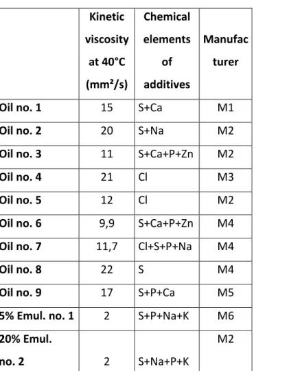
During this study, a total of 9 oils and 2 water-based emulsions from 6 different manufacturers have been tested in form tapping.
These fluids are recommended by their manufacturers as suitable for the tapping process or forming processes. They contain extreme pressure additives mainly based on either sulphur or chlorine. Their viscosities are known. In order to identify all chemical additives, oil is put on a substrate made of aluminium copper alloy and the samples are analysed with a Scanning Electron Microscope (SEM) equipped with a Energy Dispersive Spectrometer (EDS). This method does not enable determination of the content of each element present in different oils, because the intensity of the EDS peak depends mainly on the thickness of the oil film on the substrate. Nevertheless, ranking of the amount of different elements within a lubricant can be analysed and they are quoted in Table 1 in decreasing order. Oils no. 1, 2, 3 & 6 are mentioned as chlorine-free and only oils no. 4, 5 & 7 are chlorinated oils. Fig. 1 shows the spectrum of oil no. 3; except for the Al and Cu peaks due to the substrate, all the other peaks are linked to chemical elements of the oil. The quantities of different elements included in each oil are unknown, and moreover an element such as sulphur may appear in the oil in different molecules [12,13]. It can be contained in overbased sulfonates (sodium sulfonate and calcium sulfonate), sulphured-ester, and/or poly-sulphur. These compositions are only known to the oil manufacturer. Sulphured or chlorinated additives may react with iron from the worked steel at the contact surface with the tool, and they may then contribute to lubrication.
Concerning the emulsions tested, the concentrates are analysed by the same method. Two water-based emulsions are investigated, with 5% and 20% oil respectively. The appearance of potassium is explained by the fact that it is a surface active agent facilitating the emulsion of oil in water.
1 2 3 4 5 6 7 8 9 10 11 12 13 14 15 16 17 18 19 20 21 22 23 24 25 26 27 28 29 30 31 32 33 34 35 36 37 38 39 40 41 42 43 44 45 46 47 48 49 50 51 52 53 54 55 56 57 58 59 60
The work material used in this study is C70 carbon steel. Its structure is mostly perlitic due to the carbon content value, and its ultimate strength is 900 MPa.
The tapping experiments were performed on a DMC65V Deckel Maho Gildemeister 3 axis vertical machining centre equipped with a spindle controlled both in speed and position. After drilling, a boring operation is performed to calibrate the hole and to achieve an accurate hole axis straightness. Blind holes are tapped with a semi-rigid holder in order to reduce axial force due to axis synchronisation errors. The thread former is a M12×1.5 6HX tap, made of HSS-E and TiN-coated. Its design is composed of 5 lobes and a short entry taper with 3 pitches. Concerning the tapping conditions, the spindle speed is fixed at 370 rpm in all the tests, which corresponds to a tangential speed of 14 m/min at the nominal diameter. The hole diameter before tapping is equal to 11.31 mm, which leads to a thread percentage of 87%.
New taps, all coming from the same batch and cleaned with acetone, are used for each lubricant, and each is tested several times. All cylindrical samples are machined in rolled bars coming from the same batch, implying that the samples have the same hardness. The blind hole is filled with the lubricant and the thread former is covered with lubricant before tapping. During tapping, the torque and the thrust force are measured on the tapped sample with a 9273 Kistler piezo-electric dynamometer.
3.2. Torque measurement analysis
During the form tapping operation the torque varies until the spindle reverses for different reasons. Fig. 2 shows torque as a function of time, and Fig. 3 shows the tap during
working in a sample at different positions. The torque increases from time T1 to T2 when
the entry taper of the tool penetrates the workpiece. At time T2, all the lobes of the entry
taper are working the material, and the first thread is completely formed. The value of the
torque at this moment is named the Formation Torque. Even beyond T2, the torque would
continue to increase due to the increasing contact surface between the workpiece and the tool resulting from springback of the deformed material. This is the reason why thread formers are designed with a back clearance angle. The reduction of the tool diameter on
the back taper is a few hundredths of a millimeter for a 10 mm length. At time T3, the
spring back of the deformed material is equal to the back clearance of the tap and
1 2 3 4 5 6 7 8 9 10 11 12 13 14 15 16 17 18 19 20 21 22 23 24 25 26 27 28 29 30 31 32 33 34 35 36 37 38 39 40 41 42 43 44 45 46 47 48 49 50 51 52 53 54 55 56 57
still remains active, the torque will subsequently remain constant as shown in Fig. 2. And
finally, at time T4, the tap stops and travels out of the workpiece, the torque is becoming
negative. The increase of the torque from T2 to T3 is called Friction Torque. It is clear that
there is friction between the work material and the tool in the entry taper during formation of the thread by the plastic flow. Nevertheless, the term Friction Torque applies to the torque caused by the contact of the work material with the back taper which is not involved in the formation of the thread. The Mean Torque is calculated during the steady state, from
T3 to T4.
3.3. Effect of lubricant on torque
Different tests show that the torque does not always reach and remain at a constant level even though the area of the contact surface between the tool and the workpiece reaches a constant value. Fig. 4 shows the comparison of different lubricants used in tapping. The torque curves for oils no. 2 & 4 and emulsion no. 2 reach a steady-state as seen previously in Fig. 2 with emulsion no. 1. However, two other scenarios are possible:
(a) The torque may increase monotonically while the tap is working, as shown in the curve for oil no. 9. In this case it may be explained by the oil losing its lubrication due to increased temperature.
(b) The torque increases under the effect of springback of the deformed material, after which the torque decreases somewhat to reach a steady-state at a lower mean torque as seen by the curve with oil no. 1. The oil may need a higher temperature or more time to allow its additives to react, in order to increase its efficiency.
If the torque curve does not reach a steady-state, the Mean Torque is calculated from T =
1.5 s to T4, then the Friction Torque is defined in Equation (1).
Friction Torque = Mean Torque – Formation Torque (1)
Fig. 4 shows the significance of the lubricant in form tapping. The Mean Torque with the least effective oil, is 53% higher than the Mean Torque with the most effective one, i.e., oil
1 2 3 4 5 6 7 8 9 10 11 12 13 14 15 16 17 18 19 20 21 22 23 24 25 26 27 28 29 30 31 32 33 34 35 36 37 38 39 40 41 42 43 44 45 46 47 48 49 50 51 52 53 54 55 56 57 58 59 60
efficient lubricant reduces not only the Friction Torque on the back taper of the tool, but also the Formation Torque. This is an interesting point, because the Formation Torque concerns the entry taper, which is the active zone of the tool where the pressures between the tool and the work material are higher than in the back taper.
All results are presented in Fig. 5. Lubricants are ranked from best to worst by considering the Mean Torque as the criterion. This ranking would be a little different if the criterion taken into account is the Formation Torque, the maximum torque, or the tapping energy. The first four lubricants show a decreasing efficiency, where oils no. 5 to no. 7 have a comparable mean torque and the last four also present a decreasing efficiency. The Mean
Torque of oil no. 9 is only 10% lower than the emulsion no. 1. Oils with chlorine additives
do not rank well. Chlorinated additives are used less and less due to health and environmental issues. This means that it is possible to replace chlorinated oils with better ones. Concerning the emulsions, emulsion no. 1 is a little more efficient although it is a 5% water-based emulsion against 20% for emulsion no. 2. If the two emulsions are compared with water, it appears that the emulsions do not have any ability to lubricate during form tapping of high strength steels.
Friction percentage and formation percentage are respectively defined in equations (2) and (3).
% Friction = Friction Torque / Mean Torque (2)
% Formation = Formation Torque / Mean Torque (3)
All oils reduce Friction Torque compared to emulsions; moreover powerful oils decrease
Formation Torque. The trend is that the better the oil is, the lower the Friction and Formation Torque are, but the Friction Percentage rises (i.e., the Formation Percentage
decreases). As a result, it appears easier to decrease the friction on the back taper of the tool than on the entry taper. This may confirm the fact that generally the stresses are much higher in this second zone. Concerning the lubrication conditions on each lobe of the entry taper, two hypotheses may be proposed. The first is that efficient oil reduces the force on each lobe of the entry taper. The second is that it reduces only forces on the first lobes and not on the last lobes of the entry taper, where stresses would be much higher because of strain-hardening and higher depth of penetration.
1 2 3 4 5 6 7 8 9 10 11 12 13 14 15 16 17 18 19 20 21 22 23 24 25 26 27 28 29 30 31 32 33 34 35 36 37 38 39 40 41 42 43 44 45 46 47 48 49 50 51 52 53 54 55 56 57
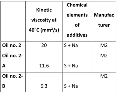
It would be interesting to determine which properties of a lubricant make it adequate for the form tapping process. A simple comparison can be done between the kinetic viscosity and the Mean Torque during tapping. However, as seen in Fig. 6 there is no correlation between these two measurements. Oil with a viscosity up to 20 mm²/s may lead to a low torque as with oil no. 2, but also to a large torque as shown with oil no. 8. As a result, additives contained in the oil may have a significant effect on the torque during the forming operation.
In order to confirm this conclusion, the manufacturer of oil no. 2 agreed to produce this oil with two other values of viscosity. It means that they are made from different base oils but contain the same additives, as it is recapitulated in Table 2. The torque measurements in Fig. 7 show that there is no significant difference between these oils. The Mean Torque is
the same, only the torque between T2 and T3 appears to change a little, which can be
explained by the fact that there is an interaction between the base oil and the additives. As a consequence, these tests confirm that the viscosity does not influence the torque during form tapping, and that the additives are the elements responsible for making a successful oil.
3.4. Lubrication and temperature
Heat generation and the associated temperature rise in manufacturing processes are significant topics of research. The rise in temperature leads to thermal softening of the work material which would be beneficial in manufacturing operations, but too high a temperature decreases mechanical properties of the tool material, and contributes to its rapid wear by different mechanisms. The lubricant is also affected by the temperature which is necessary to make the chemical reaction of additives contained in the oil possible, but excessive temperatures may cause burning of the oil. Thus, the oil is affected by the elevated temperature, and the reverse has to be considered. The operating temperatures are decreased by an efficient lubricant which would considerably reduce friction between the tool and the work material. This would lead to less energy generated directly by friction, and the stress distribution being changed, the heat created in the deformed zones is also reduced.
1 2 3 4 5 6 7 8 9 10 11 12 13 14 15 16 17 18 19 20 21 22 23 24 25 26 27 28 29 30 31 32 33 34 35 36 37 38 39 40 41 42 43 44 45 46 47 48 49 50 51 52 53 54 55 56 57 58 59 60
spindle speed (rad/s). Thus, the higher the tapping torque is, the more heat is created. However, this reasoning does not allow us to know whether the temperature is locally higher or not. 4 1 ( )
T T E Mz t dt (4)Since it is not possible to measure directly the temperature of the lubricant at the tool/work material interface, it was decided to measure it with a thermocouple (TC1) 1 mm from the
root to the 3rd thread, i.e., 4.5 mm from the top of the sample. It is not feasible to place it
close by the root because it would be inside the deformed zone with the risk of being destroyed. A second thermocouple (TC2) measures the temperature in the oil contained at the bottom of the tapped sample, as shown in Fig. 8.
TC1 measures two maxima in temperature at time 1 s and time 4 s as shown in Fig. 9. Heat appears mainly in the deformed zones of the work material and at the tool interface due to friction. Then, the heat is partially transferred to the tool, and another portion is evacuated by the lubricant which is removed out of the tapped sample. However, most of the heat is generated and conducted into the work material. The temperature at the measurement point TC1 is the consequence of different heat fluxes as shown in Fig. 8 with a simplified approach. The first maximum temperature, at time 1 s, is reached due to the heat flux F2 caused by the forming of the nearest thread. Other contributions are flux F1 coming from the upper formed thread and flux F3 which goes to the bottom of the sample where temperatures are lower. The conjunction of these different fluxes explains the second maximum 3 s later. Generally, due to the sample’s geometry, the heat is conducted to the bottom of the sample. As a result, the temperature of the oil, which is not removed from the hole by the tool, increases over a long time, as registered by the thermocouple TC2 and shown in Fig. 10.
The first maximum in temperature, called TC1max on Fig. 9, may be considered as being a characteristic temperature of the lubrication effect. Results of the temperature measurements are summed up in Fig. 11. With oil no. 2, which was classified as the second best oil in efficiency (Fig. 5), has a peak temperature of 111°C. In comparison, emulsion no. 1, which is an inefficient lubricant if the tapping torque is considered, reaches a temperature of 153°C. Thus, the temperature is correlated with the efficiency of the
1 2 3 4 5 6 7 8 9 10 11 12 13 14 15 16 17 18 19 20 21 22 23 24 25 26 27 28 29 30 31 32 33 34 35 36 37 38 39 40 41 42 43 44 45 46 47 48 49 50 51 52 53 54 55 56 57
lubricant. The temperature of oil no. 9 is higher than the one of oil no. 8 which is higher than the one of oil no. 2.
The site of the lubricant temperatures TC2 shown in Fig. 10 does not correspond to the workpiece temperature shown in Fig. 9. The temperature of emulsion no. 1 is lower than those of the three oils, whereas the emulsion leads to more heat generated. This is explained by the fact that emulsions have a higher specific heat than oils.
There is an equilibrium linked to different interactions between temperature, lubricant reaction and torque. Torque creates a thermal energy increase, the temperature allows chemical reactions of additives, and the lubricant reaction reduces the torque, as explained in Fig. 12. These measurements show that efficient lubricants become active at lower temperatures than poor lubricants.
4. Investigation of tapped samples
The tested oils have an important effect on torque, and particularly, they may change the
Formation Torque. This means that oils may change metallurgical aspects in the formed
thread. It has been shown that the additives are involved in the lubrication process. Thus, the addidives must have reacted and the chemical elements which composed them would be traceable on the thread surface.
4.1. Metallurgical analysis of the formed thread
With form tapping, the thread is obtained by the displacement of the work material. This plastic flow leads to strain-hardening of the material. The analysis of the photo micrograph of the sample shows different deformed zones such as the flank and the root of the thread. Hardness measurements were performed in order to observe the influence of the lubricant on the strain within the work material. A chemical nickel coating is used in order to measure the hardness as close as possible to the root. Fig. 13 presents Vickers microhardness measurements from 15 µm to 250 µm of the root for oil no. 2 and emulsion no. 1.
1 2 3 4 5 6 7 8 9 10 11 12 13 14 15 16 17 18 19 20 21 22 23 24 25 26 27 28 29 30 31 32 33 34 35 36 37 38 39 40 41 42 43 44 45 46 47 48 49 50 51 52 53 54 55 56 57 58 59 60
This data shows that the strain-hardening in the thread is higher when using a poor lubricant. This point is correlated with the Mean Torque, i.e., the higher the torque is during tapping, the higher is the strain-hardening. All hardness measurements taken on different samples tapped with the other lubricants confirm this point. Regarding the form of the split crest in Fig. 14, it appears that lubrication influences the formation process. So the level of friction between the thread former and the work material is affected by the lubricant and, as a result, it clearly changes the strain distribution within the deformed material. This would also mean that the strength of the thread depends on the lubricant used during tapping.
This analysis can be supported by examining the strain-hardening resulting from each lobe of the entry taper. If the bottom of the blind tapped hole is observed every 72° (i.e., 360° divided by the 5 lobes of the tool), the thread can be analyzed at different stages of formation. This method was previously explained [7]. Fig. 15 presents the Vickers
microhardness at 30 m distance from the root as a function of the number of lobes having
worked. The first 10 lobes are in the entry taper, and each one deforms the work material
to a harder state than the previous one. The 11th lobe is the first lobe in the back taper of
the tool, and there is no more strain-hardening. The curves drawn concern emulsion no. 1 and oil no. 2 as in Fig. 13. It appears that for the emulsion the strain-hardening along the thread formation is much higher than for oil no. 2. This confirms the previous results.
1 2 3 4 5 6 7 8 9 10 11 12 13 14 15 16 17 18 19 20 21 22 23 24 25 26 27 28 29 30 31 32 33 34 35 36 37 38 39 40 41 42 43 44 45 46 47 48 49 50 51 52 53 54 55 56 57
4.2. EDS analysis on the thread surfaces
It has been established that the viscosity of the oil does not influence the torque during tapping and as a result additives contained in lubricants may be the main cause affecting the torque. This hypothesis would be confirmed if high pressure additives based on sulphur and chlorine appear at the surface of the threads.
The percentage of sulphur and the appearance of chlorine on the root of the 3 pitches in the middle samples are measured with SEM equipped with EDS. Unfortunately, the SEM used is not calibrated to quantify the percentage of chlorine. The steel used has a higher machinability due to inclusions of manganese sulphide. However, the presence of these sulphides in the work material does not interfere with the measurements on the root of the thread of sulphur coming from the oil. The EDS spectrums show that there is a high peak of sulphur without the appearance of manganese, thus the measurement is not related to manganese sulphide.
Fig. 16 shows the results concerning each lubricant. The percentage of sulphur measured on the root of the sample tapped with emulsions is insignificant compared to the one tapped with oil. Thus, the poor ability of emulsions to lubricate during processing is confirmed. Sulphur is detected by EDS on the thread tapped with oil containing sulphured additives, i.e., oil no. 1 to 3 and oil no. 6 to 9. In the case of thread tapped with oil no. 4, 5 and 7 containing chlorinated additives, the appearance of chlorine is revealed by EDS analysis. Regarding the oils based mainly on sulphured additives, the weight percentage of sulphur on the thread is between 0.7% and 0.8% except for the two less efficient oils. Concerning the oils no. 8 and no. 9, the rate rises to 1.4%. These measurements are reliable, and the presence of sulphur on the thread seems to be in contradiction with the fact that its use leads to the highest torques. Several hypotheses may be proposed. The chemical reaction time for additives with iron could be too long and the tap travels out when the reaction starts. Another hypothesis is that the sulphides, which are produced by the chemical reaction of the additive, do not reduce friction. The last hypothesis is that the lubricant would be degraded by too high temperature. In the case of oil no. 9 it would be
confirmed with the increasing torque after T3 and moreover, on the last formed thread, 7%
sulphur is measured. Thus, in the case of oil no. 9, no correlation is noted between the torque, the created heat and the lubricant reaction.
1 2 3 4 5 6 7 8 9 10 11 12 13 14 15 16 17 18 19 20 21 22 23 24 25 26 27 28 29 30 31 32 33 34 35 36 37 38 39 40 41 42 43 44 45 46 47 48 49 50 51 52 53 54 55 56 57 58 59 60
Analysis of sulphur percentage on the thread with its formation is conducted on a tapped sample with oil no. 2. Fig. 17 shows an increasing percentage with the number of lobes having worked. This is correlated with the strain-hardening previously measured. During the deformation of the work material, strain energy is converted into heat and it results in a temperature rise. The strain-hardening during thread formation, resulting from higher strain energy, shows that the temperature is increasingly high on the lobe in the entry taper. This corresponds to the increase from the ambient temperature to the maximum TC1 temperature on Fig. 9. The increasing temperature causes a more and more efficient chemical reaction, implying that the sulphur percentage on the root of the thread grows.
4.3. XPS analysis of thread surfaces
It has been shown by EDS that the sulphur percentage on threads tapped with different oils is not characterizing the lubrication efficiency of the oil. Further understanding can be obtained by analyzing the sulphured layer on the threads with other devices than EDS. Thus, the analysis of the threads, tapped with two chosen oils no. 2 and 6, is realized by means of the X-ray Photoelectron Spectroscopy (XPS), which is a surface analysis technique. These two oils have quite different additive formulation (cf. §2) and show a distinct lubrication efficiency in tapping possibly related to various chemical bonds created during form tapping. This kind of surface analysis should reveal the information about the sulphur form and bring to light the possible scenario of physico-chemical reactions that took place.
Before introducing them into the analysis vacuum chamber, the threads are cut (dry machining) and washed ultrasonically in a bath of pure heptane. The oils residues have to be removed to guarantee the very investigation of the chemical reaction products of additives with the metallic surface. The zone of analysis is localized at the root of the totally formed part of thread which is the zone subjected to the heaviest contact with the tap.
The XPS analysis is carried out with a Mg K (1253.4 eV) line excitation source (VG XR2) and the detection is made by the VG ESCALAB 220i spectrometer. The X-ray power and analyzer resolution are 180 W and 0.72 eV, respectively. Advantage® software is employed for the recording and processing of XPS spectra and a Shirley background is used for their fitting. Constraints such as L/G ratio (60%) and FWHM are applied to border
1 2 3 4 5 6 7 8 9 10 11 12 13 14 15 16 17 18 19 20 21 22 23 24 25 26 27 28 29 30 31 32 33 34 35 36 37 38 39 40 41 42 43 44 45 46 47 48 49 50 51 52 53 54 55 56 57
them. The relative intensities of the spin-orbit features for the S2p3/2 and S2p1/2 peaks are
considered during the fitting of the sulphur spectra.
Determination of sulphur form (peak position) is vital in this case in comparison to gathering precise information about the atomic percentages of each chemical element individually. So, the adventitious carbon and any other surface contaminants were not removed by argon ion: an ion sputtering may accidentally modify the position of sulphur peak on XPS spectra.
The four common chemical elements discerned on XPS spectra of the tapped threads surfaces with oils no. 2 and 6 are carbon, oxygen, iron and sulphur. Among them, only sulphur spectrum is significantly different on the surfaces of the two analyzed specimens (threads tapped with oil no. 2 and 6). This observation agrees with the assumption put forward above: various chemical phenomena occurred, in which the atoms of sulphur contained in the two different blends took part.
Electron binding energies in the XPS spectrum were calibrated against the carbon C1s main peak which is considered granted at 285 eV (bonds C-C, C-H). Two other binding energies of C1s at 287 eV and 289 eV observed for both analyzed specimens can be attributed to different carbon-oxygen bonds (C-O, O-C=O, carbonate). The binding energies of O1s indicate the presence of oxides (among others, iron oxides) and confirm the presence of carbon-oxygen groups on the surfaces. The iron is easily noticeable by XPS analysis on these two samples. The most intense peaks of iron are assigned to be at
around 709.5 eV-710 eV and 711 eV corresponding to iron oxides of Fe2+ type and/or
sulphides and iron oxides of Fe3+ type respectively. Another one, significantly less intense,
at 707 eV can be attributed to the metallic iron (Fe0). The surface of tapped threads is
widely covered by iron oxides as it was confirmed by the presence of oxides on oxygen spectra. Fig. 18 shows the XPS spectra of sulphur. An important peak of sulphides at 161.3 eV and another one at 168 eV assigned to sulphates are discerned on the surface of thread formed with oil no. 6. On the surface of thread formed with oil no. 2, only one peak close to 168 eV is observed and corresponds to sulphates. Furthermore, there is no other significant peak which could be attributed to another form of sulphur existing on the surface of the thread formed with oil no. 2.
1 2 3 4 5 6 7 8 9 10 11 12 13 14 15 16 17 18 19 20 21 22 23 24 25 26 27 28 29 30 31 32 33 34 35 36 37 38 39 40 41 42 43 44 45 46 47 48 49 50 51 52 53 54 55 56 57 58 59 60
for form tapping (oil no. 6 is less efficient than oil no. 2). At first sight, it is possible that any other element contained in oil no. 6 could somehow affect and decrease the overall lubrication efficiency of this blend. Nevertheless, due to the complexity of its formulation, it is hardly possible to determine the exact chemical reactions involving all the components. This hypothesis however seems to be less probable regarding the similar quantity of sulphur detected on the surface of the thread realized with oil no. 6 in comparison to the specimen obtained with oil no. 2; the reactivity of sulphur in the case of oil no. 6 is rather comparable to the one of oil no. 2.
On the other hand, the presence of sulphates on the surface is often attributed to oxidation of sulphides or other sulphur species [14]. This explanation is probably true for the specimen tapped with oil no. 6. In the case of specimen tapped with oil no. 2, the peak of sulphates is too intense to be only due to oxidation; in the meantime, any other residual sulphur species which could be the source of oxidation is not observed. Additionally, the analysis of Na1s peak (1071 eV) shows the presence of sodium sulphate/sulphonate on the surface that obviously can be assigned to the oxygenated form of sulphur as shown on the sulphur spectra of specimen tapped with oil no. 2.
Form tapping is a severe machining operation but the temperature and the velocity of the sliding matter still remain lower than in the case of any cutting operation. Indeed, it can be supposed that in the case of the sulphur additive enclosed in blend no. 6, its atoms are very mobile and can be easily liberated during form tapping to promote the formation of sulphides (for example polysulfure). Contrary to the previous case, the sulphur additive added to oil no. 2 contains sulphur, which in the range of thermal and mechanical solicitations in form tapping, does not decompose completely and participates to the formation of chemically adsorbed layer of sulphates/sulphonates. In form tapping, the layer formed by oil no. 2 has a better anti-friction behaviour expressed by a lower tapping torque than the layer of sulphides, which is essentially characterized by its capacity of preventing the welding wear.
5. Conclusions
The present study evaluates the ability of 9 oils and 2 water-based emulsions to reduce friction in form tapping. From this study, important differences are shown to exist between
1 2 3 4 5 6 7 8 9 10 11 12 13 14 15 16 17 18 19 20 21 22 23 24 25 26 27 28 29 30 31 32 33 34 35 36 37 38 39 40 41 42 43 44 45 46 47 48 49 50 51 52 53 54 55 56 57
these lubricants, and consequently the choice of suitable oils for form tapping is necessary to obtain success with this process.
An efficient oil may reduce not only the friction on the back taper of the thread former, but also the friction force on the entry taper. As a result, the metallurgical aspects of the formed thread are affected, as the profile of the split crest and the work hardening during formation. The efficiency of oil depends mostly on its additives and less on its viscosity, and lubrication mechanism in form tapping of high strength steels is mainly achieved by chemical way. Surface analysis on the threads confirms the reaction of the fluid additives, based on sulphur, with the work material. XPS analysis points out the formation of different sulphured species on the surfaces of the threads formed with two distinct oils; the efficiency of these two lubricants in form tapping seems to be essentially affected by the chemical reactions involving sulphur and probably much less by its quantity (the sulphur percentage detected by EDS on the surfaces formed with both tested oils is quite similar). In addition, the surfaces of the threads formed with the oils that contributed to the poorest lubrication in form tapping were twice and more abounding in sulphur than those analyzed by XPS. Thus, the key to performance of a given lubricant in form tapping is surely determined by the molecular structure of the sulphur additive and its thermal behaviour. Furthermore, it would be interesting to qualify other lubrication technologies, such as Minimum Quantity of Lubricant (MQL) or solid lubricant coatings, for form tapping applications in hardened steel.
1 2 3 4 5 6 7 8 9 10 11 12 13 14 15 16 17 18 19 20 21 22 23 24 25 26 27 28 29 30 31 32 33 34 35 36 37 38 39 40 41 42 43 44 45 46 47 48 49 50 51 52 53 54 55 56 57 58 59 60
6. Acknowledgments
The authors gratefully acknowledge the Walter Prototyp and PSA Peugeot Citroën companies for their support to this research. They would like also to acknowledge Thierry Le MOGNE and Jean-Michel MARTIN for XPS analyses.
1 2 3 4 5 6 7 8 9 10 11 12 13 14 15 16 17 18 19 20 21 22 23 24 25 26 27 28 29 30 31 32 33 34 35 36 37 38 39 40 41 42 43 44 45 46 47 48 49 50 51 52 53 54 55 56 57 References
[1] Agapiou JS. Evaluation of the effect of high speed machining on tapping. Journal of Manufacturing Science & Engineering Technology ASME 1994;116:457-462.
[2] Zhitnitskii SI, Andreichikov OS. Rolling tool for rolling internal thread. Machine & Tooling 1965;36(10):33-36.
[3] Urlapov GP. Fluteless taps. Machine & Tooling 1969;15(10):46-48.
[4] Ivanov V, Kirov V. Rolling of internal threads: Part 1. Journal of Materials Processing Technology 1996;72:214-220.
[5] Chowdhary S, Burak Ozdoganlar O, Kapoor SG, DeVor RE. Modeling and analysis of internal thread rolling. Transactions of the NAMRI of SME 2002;329-336.
[6] Chandra R, Das SC. Forming taps and their influence on production. Journal of Indian Engineering 1975;55:244-249.
[7] Fromentin G, Poulachon G, Moisan A. Metallurgical Aspects in Cold Forming Tapping. Proceedings of the 18th International Conference on Manufacturing Research, 10-12 September 2002. Leeds Metropolitan University, England. Editor by K. Cheng and D. Webb, ISBN 1860583784, 373-377.
[8] Fromentin G, Etude mécanique et technologique du taraudage par déformation : application aux aciers prétraités (in french), PhD defended 22th September 2004, ENSAM Cluny, France.
[9] Henderer WE, BF von Turkovich. Theory of the cold forming tap. Annals of the CIRP 1974;23:51-52.
[10] NordTest MECH 039. Tapping torque test for cutting fluid evaluation. NordTest Method. 1998.
[11] ASTM D5619-00. Standard test method for comparing metal removal fluids using the tapping torque test machine, American Society for Testing and Materials. 2000.
[12] Hong H. Machinability of steels and titanium alloys under lubrication. Wear 1993;162-164:34-39.
[13] Haigang C. The tribological behaviours of various metallic cations in tapping of titanium alloy. Wear 2001;247:120-123.
1 2 3 4 5 6 7 8 9 10 11 12 13 14 15 16 17 18 19 20 21 22 23 24 25 26 27 28 29 30 31 32 33 34 35 36 37 38 39 40 41 42 43 44 45 46 47 48 49 50 51 52 53 54 55 56 57 58 59 60
[14] Pratt A.R., Muir I.J., Nesbitt H.W., X‐ray photoelectron and Auger electron spectroscopic studies of pyrrhotite and mechanism of air oxidation, Geochimica et Cosmochimica Acta 1994; 58(2):827‐841.
ig. captions
Fig. 1. EDS Spectrum of oil no. 3.
Fig. 2. Evolution of the torque during a form tapping operation. Fig. 3. Different positions of the tap during processing.
Fig. 4. Torque curves for different lubricants. Fig. 5. Synthesis of torque results for all lubricants Fig. 6. Mean torque versus oil viscosity.
Fig. 7. Effect of the viscosity of oil no. 2 on torque.
Fig. 8. Thermocouple localisations and heat fluxes designation. Fig. 9. Temperatures measured at 1mm from the thread root by TC1. Fig. 10. Temperature measured in the fluid by TC2.
Fig. 11. Summary of the temperatures measured. Fig. 12. Mechanical, thermal, and chemical interactions. Fig. 13. Microhardness at the root of the thread.
Fig. 14. Photo micrographs of samples made with emulsion no. 1 and oil no. 2. Fig. 15. Strain hardening along the thread formation.
Fig. 16. Sulphur weight percentage on tapped samples.
Fig. 17. Sulphur weight percentage evolution during the thread formation with oil no. 2. Fig. 18. Chemical shifts of sulphur peak on the surfaces of formed threads with oils no. 2 and 6 (XPS analysis)
Table captions
Table 1. Values of the kinetic viscosities and designations of the chemical elements.
Fig.1. EDS Spectrum of oil no. 3. Substrat e chemica l element s
Fig.2. Evolution of the torque during a form tapping operation. -1000 0 1000 2000 3000 4000 5000 0 0.5 1 1.5 2 2.5 3 Time (s) Mz To rque (N·cm ) Tap entrance Fricti on t orque Forma tion torqu e Mean to rque T1 T2 T3 T4 5% Emulsion no. 1
Fig.3. Different positions of the tap during processing. T1 T2 T3 T>T3 sampl e tap Identica l contact surface
Fig.4. Torque curves for different lubricants. 0 500 1000 1500 2000 2500 3000 3500 4000 4500 0 0.5 1 1.5 2 2.5 3 Time (s) Mz Torqu e (N·cm) Oil no. 9 Emulsion no. 2 Oil no. 4 Oil no. 2 Oil no. 1 Tap entrance +73 %
Fig.5. Summary of torque results for all lubricants. 0 500 1000 1500 2000 2500 3000 3500 4000 4500 Oil no. 1 Oil no. 2 Oil no. 3 Oil no. 4 Oil no. 5 Oil no. 6 Oil no. 7 Oil no. 8 Oil no. 9 Emul. no. 1 Emul. no. 2 Wat er Torqu e (N·c m) 0% 10% 20% 30% 40% 50% 60% 70% 80%
Mean Torque Formation Torque Friction Torque % Friction % Formation
Increasing efficiency
Fig.6. Mean torque versus oil viscosity. 0 4 8 12 16 20 24 Oil no. 1 Oil no. 2 Oil no. 3 Oil no. 4 Oil no. 5 Oil no. 6 Oil no. 7 Oil no. 8 Oil no. 9 Emul. no. 1 Emul. no. 2 Kineti c v isc osi ty a t 40 °C (mm²/ s) 0 500 1000 1500 2000 2500 3000 3500 4000 4500 Mean T orque (N·cm ) Viscosity at 40°C (mm²/s) Mean Torque (N·cm)
Fig.7. Effect of the viscosity of oil no. 2 on torque. 0 500 1000 1500 2000 2500 3000 0 0.5 1 1.5 2 2.5 3 Time (s) Mz To rque (N·cm ) Tap entering Oil no. 2 Oil no. 2-B Oil no. 2-A
Fig.8. Thermocouple localizations and heat fluxes designation. TC1 TC1 F3 F1 F4 F2 TC2
Fig.9. Temperatures measured at 1mm from the thread root by TC1. 0 25 50 75 100 125 150 175 200 0 1 2 3 4 5 6 7 8 9 10 Time (s) TC1 T em perat ure (°C) Oil no. 2 Oil no. 8 Oil no. 9 Emulsion no. 1 Oil no. 2 Emulsion no. 1 Oil no. 8 Oil no. 9 TC1max
Fig.10. Temperature measured in the fluid by TC2. 0 10 20 30 40 50 60 70 80 0 10 20 30 40 50 60 70 80 Time (s) TC 2 Tempera ture ( °C) Oil n°2 Oil n°8 Oil n°9 Emulsion n°1 Oil no. 2 Oil no. 8 Oil no. 9 TC2max Emulsion no. 1
Fig.11. Summary of the temperatures measured. 0 20 40 60 80 100 120 140 160
Oil no. 2 Oil no. 8 Oil no. 9 Emul. no. 1
Tem perat ure (°C) 0 500 1000 1500 2000 2500 3000 3500 4000 4500 Mean T orque (N·cm ) TC1max TC2max Mean Torque
Fig.12. Mechanical, thermal, and chemical interactions. Mechanical forces Additive reaction Temperature Friction reduction Heat conversion Activation
Fig.13. Microhardness at the root of the thread. 260 310 360 410 460 510 560 0 25 50 75 100 125 150 175 200 225 250 Distance from the root of the thread (mm)
Microhardn ess HV 0,0 25 Emulsion no. 1 Oil no. 2 root flank m easure m ent poin ts Ni coating
Fig.14. Photo micrographs of samples made with emulsion no. 1 and oil no. 2.
Oil no. 2 Emulsion no. 1
Fig.15. Strain-hardening along the thread formation. 200 250 300 350 400 450 500 0 2 4 6 8 10 12 14 16
Number of lobes having worked
Micro hardn ess HV 0,1 at 30 m m from t he root Emulsion no. 1 Oil no. 2
Fig.16. Sulphur weight percentage on tapped samples. 0.00% 0.25% 0.50% 0.75% 1.00% 1.25% 1.50% 1.75% 2.00% Oil no. 1 Oil no. 2 Oil no. 3 Oil no. 4 Oil no. 5 Oil no. 6 Oil no. 7 Oil no. 8 Oil no. 9 Emul. no. 1 Emul. no. 2 Sulph ur weight pe rcent age on the root o f the threa d 0 500 1000 1500 2000 2500 3000 3500 4000 4500 Mean T orque (N·cm ) % Sulphur Mean Torque (N·cm) + Cl + Cl + Cl 5%
Fig.17. Sulphur weight percentage evolution during the thread formation with oil no. 2. 200 250 300 350 400 450 0 2 4 6 8 10 12
Number of lobes having worked
Microhardn ess HV 0,1 at 30 m m from t he root 0.0% 0.4% 0.8% 1.2% 1.6% 2.0% Sulp hur weigh t pe rcent age on t he root
Oil no. 2 Microhardness
Fig.18. Chemical shifts of sulphur peak on the surfaces of formed threads with oils no. 2 and 6 (XPS analysis)
Kinetic viscosity at 40°C (mm²/s) Chemical elements of additives Manufac turer
Oil no. 1 15 S+Ca M1
Oil no. 2 20 S+Na M2
Oil no. 3 11 S+Ca+P+Zn M2
Oil no. 4 21 Cl M3
Oil no. 5 12 Cl M2
Oil no. 6 9,9 S+Ca+P+Zn M4
Oil no. 7 11,7 Cl+S+P+Na M4
Oil no. 8 22 S M4
Oil no. 9 17 S+P+Ca M5
5% Emul. no. 1 2 S+P+Na+K M6
20% Emul.
no. 2 2 S+Na+P+K
M2
Table 1. Values of the kinetic viscosities and designations of the chemical elements.
Kinetic viscosity at 40°C (mm²/s) Chemical elements of additives Manufac turer Oil no. 2 20 S + Na M2 Oil no. 2-A 11.6 S + Na M2 Oil no. 2-B 6.3 S + Na M2