HAL Id: hal-01183948
https://hal.archives-ouvertes.fr/hal-01183948
Submitted on 19 Feb 2016HAL is a multi-disciplinary open access archive for the deposit and dissemination of sci-entific research documents, whether they are pub-lished or not. The documents may come from
L’archive ouverte pluridisciplinaire HAL, est destinée au dépôt et à la diffusion de documents scientifiques de niveau recherche, publiés ou non, émanant des établissements d’enseignement et de
Using Shared Risk Link Groups to enhance backup path
computation
Mohand Yazid Saidi, Bernard Cousin, Jean-Louis Le Roux
To cite this version:
Mohand Yazid Saidi, Bernard Cousin, Jean-Louis Le Roux. Using Shared Risk Link Groups to enhance backup path computation. Computer Networks, Elsevier, 2009, 53 (9), pp.1341-1353. �10.1016/j.comnet.2009.01.001�. �hal-01183948�
Using Shared Risk Link Groups to Enhance Backup
Path Computation
Mohand Yazid SAIDI
aBernard COUSIN
bJean-Louis LE ROUX
c aIRISA/INRIA, Universit´e de Rennes I - Campus de Beaulieu, 35042 Rennes, FrancebIRISA, Universit´e de Rennes I - Campus de Beaulieu, 35042 Rennes, France
cFrance T´el´ecom, 2 Avenue Pierre Marzin, 22300 Lannion, France
Abstract
To cope quickly with all types of failure risks (link, node and Shared Risk Link Group (SRLG)), each router detecting a failure on an outgoing interface activates locally all the backup paths protecting the primary paths which traverse the failed interface. With the observation that upon a SRLG failure, some active backup paths are inoperative and do not really participate to the recovery (since they do not receive any traffic flow), we propose a new algorithm (SRLG structure exploitation algorithm or SSEA) exploiting the SRLG structures to enhance the admission control and improve the protection rate.
With our algorithm, more flexibility is provided for the backup path selection since a backup path which protects against the failure of a link belonging to a SRLG does not systematically bypass all the links of that SRLG. Moreover, our algorithm permits to save more bandwidth because it does not allocate the bandwidth for the inoperative backup paths even if they are activated.
Simulations show that our algorithm SSEA decreases the ratio of rejected backup paths and, it reduces in distributed environments the average number of messages sent to manage the bandwidth information necessary for the backup path computation.
Key words: network, local protection, SRLG, bandwidth sharing, path computation
1 Introduction
With the intense deployment of network real-time applications (voice over IP, TV, network games, etc.) in the last decade, fast recovery from network failures be-comes desirable to ensure the communication service continuity. Hence, to cope
quickly with network failures, local (proactive) protection pre-computing and often pre-configuring backup paths is preferred and adopted [1,2].
With the advent of MPLS (MultiProtocol Label Switching) [3] in the last decade, local protection is provided in efficient manner. In fact, MPLS offers a great flex-ibility for path (Label switched Path or LSP) selection and provides mechanisms allowing resource1 reservations2 and backup path preconfigurations.3 Moreover
and contrarily to the local protection in low layers (e.g. p cycles [4]), MPLS per-mits perper-mits the separation of the traffic in several classes and to choose the classes of traffic to be protected.
In order to cope with any physical failure4 in a logical (MPLS/IP) level, three types
of failure risks are defined: link, node and Shared Link Risk Group (SRLG). The first type of failure risk corresponds to the risk of a logical link failure due to the breakdown of an exclusive physical component of the logical link. The second type of failure risk corresponds to the risk of a logical node failure due to the breakdown of an exclusive physical component of the logical node. Finally, the third type of risk corresponds to a set of logical links that share a common physical component (optical fiber, crossconnect, etc.) whose failure may impact all links in the set [5–7].
Two types of backup LSP are defined for MPLS local protection [8]: Next HOP (NHOP) LSP and Next Next HOP (NNHOP) LSP. A NHOP LSP (resp. NNHOP LSP) is a backup path protecting against link failure (resp. node failure); it is setup between a primary node called Point of Local Repair (PLR) and one primary node downstream to the PLR (resp. to the PLR next-hop) called Merge Point (MP). Such backup LSP bypasses the link (resp. the node) downstream to the PLR on the pri-mary LSP. When a link failure (resp. node failure) is detected by a node, this later activates locally all its NHOP and NNHOP (resp. its NNHOP) backup LSPs by switching traffic from the affected primary LSPs to their backup LSPs.
In order to ensure that there is enough bandwidth after a failure (i.e. to guarantee the communication repair success), the backup paths should reserve the bandwidth they need beforehand. Besides, to decrease the bandwidth allocations and accept much more connection establishments, the practical hypothesis of single failure is often adopted [9,6,10,11,7,12,13]. With such hypothesis, all the backup paths protecting against failures of different components can share their bandwidth allocations (on their common links) since they cannot be active at the same time.
Several classical approaches [9,6,10,11,7,12,13] are developed to optimize the
band-1 In this paper, resource refers to bandwidth.
2 Resource reservations ensure enough resource is available after the recovery from a
fail-ure.
3 Backup LSP preconfiguration decreases recovery time down to 50 ms.
4 A single failure affects only one physical component. Such failure can affect several
width allocated to the backup paths (called also protection bandwidth). In such ap-proaches, the authors suggest to determine the cumulative bandwidth of the backup paths which would be activated on each link, after each possible failure. We note that a backup path is activated if its head-end router detects a failure on the pro-tected link or node. As only the activate backup paths can really use their re-sources, the classical approaches propose to allocate the maximum of cumulative bandwidths of backup paths which could be active at the same time on each link.
Contrarily to the protection against link and node failure risks which uses only one backup path for each primary path, the protection against a SRLG risk employs sev-eral backup paths, one for each link which belongs to the primary protected path and to the SRLG. Moreover, for fast recovery from a SRLG failure, all the backup paths which protect against the failure of links belonging to the failed SRLG will be activated simultaneously. With the observation that some activated backup paths do not really use their resources (bandwidth) after a SRLG failure (because the traffic of the primary paths they protect was switched towards other backup paths which bypass their head-end routers), we propose in this article to enhance the protection quality and increase the bandwidth sharing by extending its application to some activated backup paths. In our approach, we explore the SRLG structures to deter-mine the active backup paths which do not really use their resources after certain SRLG failures. Such active backup paths are in reality inoperative after such fail-ures since they do not consume the bandwidth. In order to decrease the protection bandwidth that is allocated on each link, we propose to limit the concurrence for protection bandwidth to the backup paths which can be operative at the same time. In our proposition, more flexibility is provided for backup path selection since a backup path does not systematically bypass all the links sharing a SRLG with the protected link.
The rest of this article is organized as follows: In Section 2, we review some works related to the bandwidth sharing. In Section 3, we give a SRLG structure based classification of the backup paths that permits to improve the backup path computa-tion. In our classification, the backup paths are grouped into two sets: the operative backup paths which receive the rerouted traffic after a failure, and the inoperative backup paths which do not receive any traffic after a failure, although they are active. In Section 4, we propose and describe a new algorithm (SRLG Structure Exploitation Algorithm or SSEA) which decreases the protection bandwidth allo-cations and provides more flexibility for the backup path selection. In Section 5, we give some ideas and propositions for the implementation of the SRLG structure ex-ploitation algorithm in both centralized and distributed environments. In Section 6, we present and analyze some simulation results and we give, in Section 7, some conclusions.
2 Related Work
With the increasing interest for local proactive protection in the last decade, several works [1,2,9,6,10,11,7,12,13] have been devoted to the determination of algorithms computing the backup paths. To minimize the quantity of bandwidth allocated on links while avoiding the bandwidth constraint violation (bandwidth insufficiency), the Backup Path Computation (BPC) algorithms require the knowledge of some information like the primary and backup paths, bandwidth allocations and protected risks.
Depending on the number of simultaneous failures that we would tolerate, the quan-tity of bandwidth reserved on each link for protection can be high (large number of simultaneous failures) or low (small number of simultaneous failures). Indeed, the number of simultaneous failures that can be processed successfully determine all the failure scenarios, which in turn control the number and structures of the backup paths which provide the protection. Due to the rarety of multiple failures5 and the
complexity to protect (in local and proactive manner) against this type of failure, and in order to increase the bandwidth availability (increase the bandwidth sharing), most of works in the literature consider only single failures [9,6,10,11,7,12,13]. With such type of failure (i.e. a single failure), the quantity of bandwidth that should be reserved on each link for protection, depends on the cumulative band-width of the paths which could be active at the same time after any single failure occurrence. Two strategies of bandwidth sharing are defined to reduce the protec-tion bandwidth allocaprotec-tions: backup-backup bandwidth sharing and backup-primary bandwidth sharing.
In the first strategy (backup-backup bandwidth sharing), the quantities of protec-tion bandwidth allocated on links are decreased significantly with the applicaprotec-tion of the bandwidth sharing between the backup paths [9,6,10,11,7,12,14]. This type of bandwidth sharing is made possible thanks to the hypothesis of single failures which ensures that some backup paths cannot be active (they do not use their band-width) at the same time. Thus, only the backup paths protecting against a same risk can be in concurrence for bandwidth allocation.
When a new backup path is being computed, control admission is applied on all its links to verify the bandwidth constraints. Two concepts are defined in [6] to ensure the respect of the protection bandwidth constraints: protection failure risk group and protection cost.
The protection failure risk group of a backup path b, denoted PFRG (b), is a set composed of all the risks whose failure activates the backup path b. With the defi-nition of the function Act as follows (BP aths is the set of all the backup paths and
Risks is the set of all the network failure risks):
Act : BP aths × Risks → {0, 1} (b, r) 7→ y =
1 if b is active upon the failure of r 0 otherwise
We determine the protection failure risk group of a backup path b as follows:
P F RG (b) = {r\r ∈ Risks and Act (b, r) = 1} (1)
The protection cost of a risk r on a link λ, denoted δλ
r, corresponds to the cumulative
bandwidth of the backup paths which will be activated on the unidirectional link
λ upon a failure of the risk r. It is computed as follows (bw (b) is the bandwidth
required by the backup path b):
δλ r =
X
b ∈ BP aths ∧ λ ∈ b
Act (b, r) × bw (b) (2)
For a SRLG risk srlg composed of link risks (l1, l2, .., ln), the protection cost on a
link λ verifies always the following equality: δλ srlg =
P
0<i≤nδlλi.
To compute a new backup path b, only the unidirectional links λ verifying the fol-lowing inequality can be used:
P rλ+ Maxr∈P F RG(b)(δrλ) + bw (b) ≤ Cλ (3)
where P rλis the the cumulated bandwidth of the backup paths traversing the arc λ
and Cλis the capacity of the arc λ.
To cope successfully with any single failure, the amount of protection bandwidth
Bkλ that should be reserved on each link λ is determined as follows:
Bkλ = Maxr(δλr) (4)
The backup-backup bandwidth sharing strategy improves substantially the band-width use and decreases the blocking probability. It is easy to be deployed in cen-tralized environments where the unique BPCE (Backup Path Computation Element) knows all the bandwidth information (like protection costs, link capacities, cumu-lative primary bandwidths, etc.) that is required for the backup path computation. Indeed, the centralized BPCE can deduce the values of all the bandwidth param-eters used in (3) from the structures and properties of the paths which it has pre-viously computed. In distributed environments however, the advertisement of the bandwidth information that is required for the backup path computation is costly
and could overload the network. Thus, using heuristics aggregating and/or reducing this bandwidth information before its advertisement in the network could give some interesting and practical solutions [9,11,7,12,14]. For instance, to decrease the size and frequency of the advertisement messages, the Kini’s heuristic [9] suggests to approximate all the protection costs on a given unidirectional link by the highest protection cost on that link (i.e. ∀(λ, r) : δλ
r is approximated by Maxr(δrλ)). In
this way, a given unidirectional link λ can be used to establish a new backup path b if it verifies the following inequality: P rλ+ Maxr(δrλ) + bw (b) ≤ Cλ.
In the second strategy (backup-primary bandwidth sharing), another style of band-width sharing (bandband-width sharing between the primary and backup paths) is applied to decrease the protection bandwidth allocated on links. This type of sharing was proposed for the first time in [13]. It suggests to (pre)allocate the bandwidth freed by the deactivated (or bypassed) primary path segments upon a failure of a risk r to the backup paths which will be activated to recover from that failure. For in-stance, when a protected link (resp. an unprotected link) u-v traversed by a primary path p fails, a quantity of bandwidth equal to the bandwidth of p is freed on all the links located between the end nodes of the backup path repairing the primary path
p (resp. on all the links located between the failed link and the destination node
of the primary path p). Such freed bandwidth is then assigned to the backup paths which will be activated to recover from the failure of link u-v.
To avoid the violation of the bandwidth constraints with this second strategy, only the unidirectional links λ verifying the following inequality can be selected to be in a new backup path b:
P rλ+ Maxr∈P F RG(b)(δrλ+ bw (b) − Frλ, 0) ≤ Cλ (5)
To cope successfully with any single failure, the amount of protection bandwidth
Bkλ that should be reserved on each link λ is determined as follows:
Bkλ = Maxr(δλr − Frλ, 0) (6)
where Fλ
r is the total primary bandwidth freed on the link λ after a failure of the
risk r.
Compared to the first strategy of bandwidth sharing, this second strategy can en-hance the bandwidth availability but it introduces several new drawbacks. Firstly, it complicates the resource preemption since the elimination of a primary path does not systematically free the associated bandwidth (because the bandwidth could be shared between a primary path and some backup paths). Secondly, it increases the amount of information that should be advertised in the network to enable the BPC to be performed in distributed environments. Concretely, in addition to the informa-tion required to perform the control admission with the first strategy, the applicainforma-tion
of the second strategy of bandwidth sharing requires the knowledge of the quanti-ties of primary bandwidth freed on the links for all single failures.
Although there are some activated backup paths which do no receive any traffic after a SRLG failure, both the bandwidth sharing methods of the first and the second strategies allocate them bandwidth. This wastes bandwidth and blocks uselessly some protection requests.
3 Motivations
For fast recovery, each router detecting a failure on one of its outgoing interfaces activates locally all the backup paths which protect the primary paths traversing the failed interface. Although active, some backup paths (inoperative backup paths) do not participate to the recovery of the affected communications because the traf-fic was already redirected by upstream routers onto other backup paths (operative backup paths) bypassing their head-end routers.
By limiting the concurrence for the protection bandwidth to the operative backup paths, we decrease the protection bandwidth allocations. Besides, with the restric-tion of the protecrestric-tion failure risk group of a backup path b to the risks whose failure operates the backup path b, we provide more flexibility for the path selection.
Before describing our improvement propositions, we show in the next subsection the difference between the set of the active backup paths and the set of the operative paths, upon failure. Next, we propose and describe an algorithm permitting the determination of the operative backup paths, by using the structures of the SRLGs.
3.1 Active backup paths vs. operative backup paths
Due to the difficulty to distinguish quickly between the types of failure (node, link or SRLG), each router detecting a failure on an outgoing interface activates all the backup paths which protect the primary paths traversing6 the affected interface.
As a single physical failure can affect many logical links (e.g. in case of a SRLG failure), several backup paths protecting a same primary path can be activated upon one single physical failure. In some situations, the head-end router of an activated backup path b1is bypassed by another activated backup path b2that protects a same
primary path. In such a case, the backup path b1 does not receive and reroute the
traffic of the affected primary path; it is considered as inoperative since it does not
6 If a node failure can be distinguished quickly from a link failure, only NNHOP paths are
Fig. 1. Local protection of a primary path
really use its resources (particularly the bandwidth). Hence, the bandwidth allo-cated for such inoperative path can be freed and realloallo-cated to other paths. Contrar-ily to the backup path b1, the other backup path b2really participates to the recovery
since it reroutes the traffic of the affected primary path. This path is considered as
operative. Its resources (particularly the bandwidth) cannot be reallocated to other
paths.
In figure 1, two backup paths b1A(A→F→G→D) and b1B(B→C→E→ H→G→D)
are setup to protect the primary path p1 (A→B→D) against the failure of the four
following risks: node B, link A-B, link B-D and SRLG srlg = (A-B, B-D). When the router A (resp. router B) detects a failure on the interface leading to its adjacent router B (resp. router D), it activates locally the backup path b1A(resp. b1B) which
protects the unique primary path traversing the failed interface. Hence, for the fail-ure of node B or the failfail-ure of link A-B (resp. the failfail-ure of link B-D), traffic of the affected primary path p1 will be switched onto the unique activated backup path
b1A (resp. b1B). As only one outgoing interface of the primary path routers can be
affected upon a single link or a single node failure, we conclude that at most one backup path per primary path could be activated. As a result, all the backup paths activated to recover from a link or node failure really receive and reroute the traffic
(a) Two operative backup paths upon the SRLG failure
(b) One operative backup path upon the SRLG failure
Fig. 3. Operative backup paths
of the affected primary paths.
With risks of type SRLG however, some activated backup paths do not receive or reroute the traffic of the affected primary paths. For instance, when the SRLG srlg in figure 1 fails, all the end routers of the srlg’s links (i.e. routers A, B and D) will detect a failure. As a result, all the backup paths protecting an affected primary path and whose head-end router is an end router of the links belonging to the failed SRLG will be activated (cf. figure 2). Typically, the backup path b1A(resp. b1B) will
be activated since it protects the affected primary path (p1) and its head-end router
A (resp. B) is an end router of a link A-B (resp. B-D) belonging to the affected
SRLG srlg. As the traffic switching toward a backup path results in the bypassing of a primary path segment located between the head-end and the tail-end routers of the backup path, we deduce that only the backup path b1Areceives and reroutes
the traffic of the affected primary path p1 after the recovery from the failure of the
SRLG srlg. Indeed, after the activation of the backup path b1A, the traffic of the
primary path p1 is forwarded on the path A→F→G→D: the head-end router B of
the second activated backup path b1Bis bypassed and thus, no packet traverses this
backup path.
3.2 Exploiting the SRLG structures to determine the set of operative backup paths
In order to determine the set of operative backup paths OP Br upon a failure of
a risk r, we consider the simple risks (node and link risks) and composite risks (SRLGs). With a simple failure risk r, the operative backup path set OP Bris
com-posed of all the activated backup paths upon a failure of r (cf. section 3.1). With a composite risk srlg, a backup path b protecting a primary path p is in the operative backup path set OP Bsrlg if and only if:
(1) The backup path b protects against the failure of a link belonging to the SRLG
srlg.
(2) There is no backup path b’ (b’ 6= b) such as:
• b’ protects the primary path p against the failure of a link belonging to the
SRLG srlg,
• The sub-path of p located between the end routers of b’ contains, as transit
router, the head-end router of the backup path b.
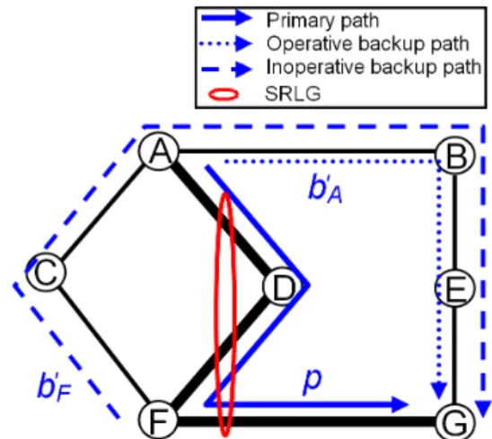
To better understand the procedure of determination of the operative backup paths upon a SRLG failure, let us consider an example. In figure 3, a primary path p (A→D→F→G) traversing the unique SRLG srlg = (A-D, D-F, F-G) of the net-work is established. To protect this primary path against the failure of link F-G, we setup a same NHOP backup path F→C→A→B→E→G in both sub-figures (bF
in the sub-figure 3(a) and b0
F in the sub-figure 3(b)). To protect the primary path p against the failure of node D (and against the failure of link A-D), we used a
different backup path in each sub-figure. Hence, in sub-figure 3(a), we setup the backup path bA(A→C→F) and in sub-figure 3(b), we configured the backup path b0
A(A→B→E→G).
Upon a failure of the SRLG srlg, the nodes A and F activate the backup paths bAand bF in the sub-figure 3(a) (resp. the backup paths b0Aand b0F in the sub-figure 3(b))
for recovery. In figure 3(a), both the backup paths bAand bF become operative after
the recovery from the SRLG failure. In fact, the backup path bA(resp. bF) protects
the primary path p against the failure of a srlg’s link A-D (resp. F-G) and its head-end router A (resp. F) does not belong to the primary path segment located between the end routers F and G (resp. A and F) of the unique other backup path bF (resp. bA) protecting the primary path p (against the failure of a link in the same SRLG srlg). In figure 3(b) however, only the backup path b0
A becomes operative (for the
same reasons as bA in figure 3(a)) upon the failure of the unique network SRLG srlg. The second backup path b0
F is inoperative upon the failure of the SRLG srlg
since there is another backup path b0
Averifying these two conditions: (1) b0Aprotects
the primary path p (i.e. the same primary path as the one protected by b0
F) against
the failure of a link (A-D) belonging to srlg. (2) The sub-path (A→D→F→G) of
p located between the end routers (A and G) of b0
A contains, as transit router, the
head-end router (F) of the backup path b0 F.
4 Using SRLG structures to enhance the BPC
As described in the previously, the exploitation of the SRLG structures permits to determine the operative backup paths after a SRLG failure. In this section, we show that we can enhance the backup path computation with the exploitation of the SRLG structure information. Typically, we reduce the protection bandwidth allo-cations by limiting the concurrence for the protection bandwidth to the operative
backup paths. Besides, we provide more flexibility for the backup path selection by restricting the set of failure risks that should be bypassed by the backup paths.
4.1 Decreasing the bandwidth allocation
Instead of using the activity state of backup paths to allocate the protection band-width, we propose here to exploite the operativity state of backup paths to reduce the protection bandwidth allocations. Before showing how to utilize the operativity state of backup paths to enhance the protection bandwidth allocation, let us defining a new function Op as follows:
Op : BP aths × Risks → {0, 1} (b, r) 7→ y =
1 if b is operative upon the failure of r 0 otherwise
where: BP aths is the set of all the backup paths and Risks is the set of all the network failure risks.
As only the operative backup paths receive traffic upon failure, we propose to limit the concurrence for the protection bandwidth allocation to the operative backup paths. In this way, the protection bandwidth allocations are reduced since a backup path which is inoperative after a failure of a given SRLG does not require to reserve any unit of bandwidth to cope with the failure of that SRLG.
To manage the set of risks whose failure operates a backup path b, we reduce the protection failure risk group of b and define the Restricted Protection Failure Risk
Group of b (or RPFRG (b)) as follows:
RP F RG (b) = {r\r ∈ Risks and Op (b, r) = 1} (7)
In addition to the reduction of the protection failure risk group set, we modify (2) to exploit the operative/inoperative state information when the backup paths are computed. Hence, we define the protection price γλ
r as the cumulative bandwidth
of the operative backup paths on the unidirectional link λ upon the failure of the risk r. It is determined as follows:
γrλ = X
b ∈ BP aths \ λ ∈ b
Op (b, r) × bw (b) (8)
With the substitution of the couple (PFRG (b), δλ
in (3), (4), (5) and (6), we obtain the formulas ensuring the respect of the bandwidth constraints and allowing the computation of the minimal protection bandwidth to be allocated on each unidirectional link.
Concretely, with the backup-backup bandwidth sharing, we have:
P rλ+ Maxr∈RP F RG(b)(γrλ) + bw (b) ≤ Cλ (9)
Bkλ = Maxr(γrλ) (10)
With the primary-backup bandwidth sharing, we have:
P rλ+ Maxr∈RP F RG (b)(γrλ+ bw (b) − Frλ, 0) ≤ Cλ (11)
Bkλ = Maxr(γrλ− Frλ, 0) (12)
Since the set of the operative backup paths is included in the set of the activated backup paths (i.e. ∀ b ∈ BP aths : RPFRG (b) ⊆ PFRG (b))), we deduce that all the protection prices are lower or equal to their corresponding protection costs (∀(r, λ) : γλ
r ≤ δλr). As a result, much more protection bandwidth is saved.
Example: Let us applying the backup-backup bandwidth sharing to the link A→B in figure 3(b).
Without the exploitation of the SRLG structures, we compute the minimal protec-tion bandwidth Bk1AB allocated on the link A→B as follows:
Bk1AB = Max(δADAB, δDAB, δF GAB, δABsrlg) = δsrlgAB = 2 × bw (p)
With the exploitation of the SRLG structures, we compute the minimal protection bandwidth Bk2AB allocated on the link A→B as follows:
Bk2AB = Max(γADAB, γDAB, γF GAB, γsrlgAB) = γsrlgAB = bw (p)
Thus, we note that Bk2AB = 50% Bk1AB
By assuming that CAB = 2 × bw (p), in the first case no new primary path (resp.
backup path protecting against the risks in {A-D, D, F-G, srlg1}) can traverse the
link A→B whereas in the second case any new primary path p0 (resp. any backup
path b0) of bandwidth bw (p0) ≤ C
AB/2 (resp. bw (b0) ≤ CAB/2) can be routed on
the link A→B. Thus, we have decreased the bandwidth allocation for the backup paths and provide the capability to setup more of primary or backup paths with the same overall network resource.
4.2 Providing flexibility for the backup path selection
In addition to the protection bandwidth decrease, the exploitation of the SRLG structures in the BPC has another important advantage: it provides more flexibility for the backup path selection and improves the quality of protection (i.e. the num-ber of protected risks on a primary path is increased) by reducing the set of risks that a backup path must bypass. In our approach, a new backup path b does not systematically bypass all the SRLGs containing the link to be protected. Instead, only the node and link to be protected and the SRLGs whose failure operates the new backup path b should be bypassed (i.e. only the risks in RPFRG (b)).
Since the set of links (and nodes) that a backup path should bypass must be known before the start of its computation, to apply our approach it would be necessary to determine beforehand whether a backup path is operative or not after a failure of any risk. By analyzing the sufficient conditions (cf. section 3.2) allowing the determination of the operative backup paths, we deduce that the links traversed by a backup path have no incidence on the operative state of that backup path upon failure. Indeed, only (1) the protected link and node, (2) the head-end router of the backup path b in computation, and (3) all the backup paths protecting a same primary path as b against the failure of an upstream link (which belongs to the same SRLG as the protected link) to the link to be protected, are used to deduce the operative state of b upon any given failure. Thus, the risks forming the restricted protection failure risks group of any backup path can be deduced before its computation, in condition that the backup paths protecting against the failures of upstream links are completely determined.
In figure 3(b) for instance, any computed backup path b0
D protecting the primary
path p against the failure of the link D→F is inoperative upon the failure of the SRLG srlg. Indeed, upon such failure, the traffic is switched by the router A onto the backup path b0
A which joins the primary path p on a router G downstream to
the head-end router D of the backup path b0
D. Since after the recovery from the
failure of the SRLG srlg, the rerouted traffic reaches its destination router G without traversing the path b0
D, we conclude that, independently on the links forming b0D,
this last backup path b0
D is inoperative upon a failure of the SRLG srlg. Thus, the
new backup path b0
D can utilize the arc D→A to protect against the failure of its
next hop, although the link D-A and the link to be protected D-F belong to the same SRLG srlg. This permits to decrease the blocking probability (i.e. probability that a new request be rejected) and provides more flexibility for the backup path selection.
4.3 SRLG structure exploitation algorithm (SSEA)
In order to decrease the protection bandwidth allocations (cf. section 4.1) and to offer more flexibility for the backup path selection (cf. section 4.1), we propose a new algorithm SSEA (cf. algorithm 1) taking into account the SRLG structures to enhance the BPC. Thus, to compute a new backup path b, we determine in the first step of our algorithm SSEA the restricted protection failure risk group of the backup path b (i.e. RPFRG (b)). This restricted protection failure risk group is formed of all the elements in PFRG (b) except the risks whose failure does not operate the backup path b. In order to denote the elements of RPFRG (b), we say that a given risk is really protected by the backup path b if and only if such risk is in RPFRG (b).
In the second step of our algorithm SSEA, we eliminate from the network topology all the links and nodes which belong to the risks in RPFRG (b). In this way, no failure risk can affect simultaneously both a primary path and one of its backup paths. Obviously, since the set of risks to be bypassed by each new backup path is reduced, more flexibility is provided for the path selection.
In order to ensure the respect of the bandwidth constraints, we apply in the third step Algorithm 1 Computation of a backup path b with the SRLG structure exploitation algorithm
inputs
A graph G = (V, E) corresponding to the network topology. V is the set of vertices (routers) and E is the set of edges (links)
begin algorithm
1. {Determination of the set RPFRG (b) which is composed of the risks whose failure operates the backup path b}
RPFRG (b) ← {r \ Op (b, r) = 1}
2. {Determination of the links which should be bypassed by the backup path b}
E” ← {λ ∈ E \ ∃ r ∈ RPFRG (b): λ ∈ r}
{Determination of the nodes which should be bypassed by the backup path b} V” ← {n ∈ V \ ∃ r ∈ RPFRG (b): n ∈ r}
3. {Determination of the links verifying the bandwidth constraints} if backup backup sharing only then
E’ ← {λ \ λ ∈ E ∧ P rλ+ Maxr∈RP F RG(b)(γrλ) + bw (b) ≤ Cλ}
else
E’ ← {λ \ λ ∈ E ∧ P rλ+ Maxr∈RP F RG(b)(γrλ+ bw (b) − Frλ, 0) ≤ Cλ}
end if
4. {Determination of the backup path b}
Use any local protection technique (one-to-one backup or facility backup) and any path computation algorithm to determine the backup path b on the graph
G’ = (V \ V”, E’ \ E”)
Fig. 4. A backup path traversing a link of a SRLG containing the protected link
of our algorithm SSEA inequality 9 (for the backup-backup bandwidth sharing) or inequality 11 (for the primary-backup bandwidth sharing) to select the links which can be used for the next backup path computation. Clearly, all the links which do not satisfy inequality 9 (or inequality 11 for the primary-backup bandwidth sharing) are pruned from the network topology before the BPC starts.
In the last step of our algorithm SSEA, we deduce one backup path providing the desired protection by running any path computation algorithm (e.g. CSPF) with the use of any local protection technique (one-to-one backup protection or facility backup protection [8]). Thus, our algorithm is generic and compatible with any path computation algorithm and any local protection technique.
To better understand our algorithm, let us consider the example in figure 3(b). Sup-pose that we are trying to compute a new backup path b0
D protecting the primary
path p against the failure of the node F and link D-F. Assume also that all the net-work links have a capacity of one unit. Independently on the chosen local protection technique, the backup path b0
D must interconnect node D to node G.
With the application of the classical BPC algorithms, no path can support b0 D since
such path would bypass all the links (A-D, D-F, F-G) belonging to the SRLG srlg (note that srlg is in PFRG (b0
D) and srlg includes the protected link D-F). With our
algorithm SSEA however (step 1 of algorithm 1), the probability to determine a path for b0
D is increased since the set of risks that the backup path b0D should bypass
is reduced to the sub-set RPFRG (b0
D) (note that RPFRG (b0D) ⊆ PFRG (b0D)).
Typ-ically, the links A-D and F-G of the SRLG srlg can be used to establish the backup path b0
D since srlg does not belong to RPFRG (b0D) (RPFRG (b0D) = {D-F, F}). In
the second step of algorithm 1, we eliminate from the network topology, the links (link D-F) and nodes (node F) composing the risks of RPFRG (b0
D). In the third
step of algorithm 1, we eliminate from the network topology the unique (unidirec-tional) link A→D which does not verify (9) (A→D is also the unique unidirectional link which does not verify (11)). After that, we can run any CSPF algorithm to
de-termine the unique backup path D→A→B→E→G interconnecting node D to node
G (figure 4).
Note that the three backup paths b0
A, b0D, and b0F (in figure 4) share totally their
band-width on the common path segment A→B→E→G although they protect against the failure of links belonging to the same SRLG. This sharing does not induce any bandwidth constraint violation because the three backup paths b0
A, b0D, and b0F
can-not be operative at the same time.
5 Implementation requirements for the SRLG structure exploitation algo-rithm
With a centralized implementation of the SRLG structure exploitation algorithm, the unique BPCE can store all the information about the network topology, the SRLG structures and the path properties (traversed links, type, bandwidth, etc.). From such information, the centralized BPCE determines the bandwidth parame-ter values of each link (cumulative primary bandwidth, protection prices, primary bandwidth freed) and deduces the best backup paths.
We note that to improve the protection quality, the centralized BPCE should es-tablish a computation order for the backup paths protecting a same primary path. Indeed, to determine the final operative state of each backup path (cf. section 3.2), the BPCE should begin with the protection of the links closest to the head-end router of each primary path.
With a distributed implementation of the BPC taking account of the SRLG struc-tures, a comparable information as that transmitted in the classical approaches [9,6,10,7,12,13] is sufficient to avoid the violation of the bandwidth constraints. For instance, the information advertised with the approach described in [6,10,12] is sufficient to decrease the bandwidth allocation. However, a very slight transfor-mation of the advertised infortransfor-mation (replacement of the protection cost values by the corresponding protection price values) is required with [9,7,13].
To enhance the protection quality with the distributed approaches, it is necessary that each BPCE determines, upon any failure, whether the backup path that is be-ing computed is operative or not before the start of its computation. This can be done by establishing a computation order for the backup paths which protect the same primary path (against the failure of the same SRLG). Typically, before start-ing the computation of a new backup path b, each PLR should verify that all the backup paths, which protect against the failures of upstream links of the primary path protected by b, are already computed and configured.
order of backup paths can be imposed. Concretely, each PLR can notify7 its
down-stream routers of the accomplishment of the configuration of its backup path. Thus, to guarantee the respect of the backup path computation order, each PLR should wait for the notifications of all its upstream routers before it starts to compute its backup path.
6 Analysis and simulation results
6.1 Simulation model
In order to evaluate the performances of the SRLG structure exploitation algorithm (SSEA), we compared it to the Kini’s heuristic and TDRA algorithm. We chose the Kini’s heuristic for its practicability whereas we opted for the TDRA algorithm for its efficiency to determine the backup paths reducing the protection bandwidth allocation.
6.1.1 Comparison metrics
Four metrics are used for the comparison: ratio of rejected backup paths (RRP), relative gain in backup path rejection (RGR), normalized SRLG bandwidth (NSB) and average number of messages (ANM) transmitted in the network per configured backup path.
The first metric measures the ratio of backup paths that are rejected because of the lack of protection bandwidth on the network links. It corresponds to the ratio be-tween the number of backup path requests that are rejected and the total number of backup path requests (RRP = #rejected protection requests / #protection requests).
The second metric calculates the gain in the RRP values obtained by using a new BPC method instead of an old one. It is determined as follows: RGR (newMeth,
oldMeth) = ( RRP (oldMeth) - RRP (newMeth) ) / RRP (oldMeth).
The third metric measures the amount of bandwidth allocated on links to protect against the SRLG failures. It is determined as the ratio between the total amount of bandwidth dedicated for the protection against the SRLG failures and the cumu-lated bandwidth of the backup paths.
For the SRLG structure exploitation algorithm, we have:
NSB =P(r is a SRLG, λ ∈ E)(γλ r) /
P
(r is a link, λ ∈ E)(δλr)
7 The notifications can be included in the RSVP path messages refreshing the primary
(a) Medium size topology (95 risks) (b) Large size topology (162 risks) Fig. 5. Test topologies
For the TDRA algorithm and the Kini’s heuristic, we have:
NSB =P(r is a SRLG, λ ∈ E)(δλr) /
P
(r is a link, λ ∈ E)(δrλ)
The fourth metric counts the (average) number of messages traversing the network links, after each backup path establishment, to maintain and update the protection bandwidth information necessary for the BPC (ANM = Pλ∈E #messages travers-ing (λ) / #accepted protection requests where E is the set of network unidirectional
links).
Contrarily to the values of the metrics RRP, RGR and NSB, those of the metric
ANM depend strongly on the implementation type (centralized or distributed) and
on the mechanism distributing the information necessary for the BPC (flooding or targeted advertisements). In a centralized environment, any BPC demand is trans-mitted to the centralized server which processes it and sends back the computation results to the requesting router. Hence, independently on the bandwidth sharing strategies and on the BPC algorithms, the number of messages transmitted in the network to process a set of requests is always the same. Accordingly, it is pointless to compare the ANM of our proposition to those of the classical centralized BPC ap-proaches. In a distributed environment, the BPC requests are generally processed by the backup head-end routers themselves. As a result, no message (or a very small number of messages) is transmitted in the network to send the BPC demands and receive the results from the servers (BPCEs). However, to maintain an updated bandwidth information about the shared parameters (protection prices/costs of the SRLGs), some BPCEs should communicate. Two main processes are used: flood-ing and targeted advertisement. In the simulations presented here, we opted for the targeted advertisement implementation since it reduces the ANM values by limiting the set of routers receiving the bandwidth information (cf. [12,7]).
6.1.2 Topologies, SRLGs and traffic matrix generation
Two well known network topologies are used for our simulation. The first topology (USA network), depicted in figure 5(a), is composed of 28 routers and 45 bidirec-tional links. It is a network topology of a medium size where the average degree of nodes is equal to 3.21. To take SRLG failures into account, we added to the topol-ogy in figure 5(a) 22 SRLGs. These SRLG are generated so that the protection against the failure of any risk remains physically possible. The second topology, depicted in figure 5(b), is composed of 50 routers and 87 bidirectional links. It is a network topology of a large size where the average degree of nodes is equal to 3.48. To take SRLG failures into account, we added to this topology (figure 5(b)) 25 SRLGs. These SRLG are generated so that the protection against the failure of any risk remains physically possible.
The traffic matrix is generated randomly and consists of requests arriving one by one and asking for quantities of bandwidth uniformly distributed between 1 and 10. The head-end and tail-end routers of each primary path are chosen randomly among the network routers.
6.1.3 Primary and backup path computations
To focus only on the impact of our proposition on the protection bandwidth allo-cation and on the protection quality, we separated the task of primary path compu-tation from that computing the backup paths (i.e. the task computing the primary path is independent from that computing the backup paths). For this to be possible, we divided the capacity of each unidirectional link in two disjoint pools: primary pool and protection pool. The primary pool is used to allocate the bandwidth for the primary paths whereas the protection pool is used for backup path bandwidth allocations.
In our simulations, we considered that the primary pool capacities are sufficient to satisfy all the requests of primary path establishment. In this manner, the same primary paths, which are computed according to the shortest path first algorithm (SPF with unitary weights), are used to compare SSEA, TDRA and Kini’s heuristic.
All the protection pool capacities of the network links in figure 5 are equal to 100 units except the bold links in figure 5(a) which have a capacity of 300 units. The backup paths are computed according to the constrained shortest path first algorithm (CSPF with unitary weights). Concretely, each backup path computed with SSEA (resp. with TDRA or Kini’s heuristic) must bypass all the risks in its restricted protection failure risk group (resp. its protection failure risk group). In addition, each link λ belonging to a backup path b computed with SSEA (resp. with TDRA and Kini’s heuristic) must verify the following inequality: Maxr∈RP F RG(b)γrλ
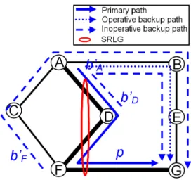
(a) Medium size topology (b) Large size topology Fig. 6. Ratio of rejected backup paths (RRP)
Each primary node, different from the destination node and its upstream node, com-putes a NNHOP backup path to protect against both its next link and node on the primary path. The upstream node of the primary path destination node uses a NHOP backup path to protect against the failure of its next link.
At each establishment of 20 primary paths, the four metrics RRP, RGR, NSB and
NMN are computed for all the compared methods. We note that our results
corre-spond to average values over 1000 runs.
6.2 Results and analysis
Figure 6 and figure 7 depict the evolution of RRP and RGR respectively as a func-tion of the number of primary paths setup in the network (i.e. as a funcfunc-tion of the network load). The figure 6 shows clearly that the RRP values of SSEA algorithm are lower and better (except for the 40 first primary paths where the RRP values of the three compared methods are null) than those of TDRA algorithm which are in turn lower than those of Kini’s heuristic.
(a) Medium size topology (b) Large size topology Fig. 7. Relative gain in backup path rejection (RGR)
(a) Medium size topology (b) Large size topology Fig. 8. Normalized SRLG Bandwidth (NSB)
The wide difference in the RRP values between the Kini’s heuristic and the SSEA algorithm is essentially due to the partial knowledge of the protection bandwidth information with the Kini’s heuristic whereas the SSEA algorithm utilizes and has a complete knowledge of the protection bandwidth parameter information. Thus, the Kini’s heuristic overestimates the bandwidth parameters required for the BPC whereas the SSEA algorithm uses exact values of these parameters in its computa-tions. Obviously, the wide difference in the RRP values between the Kini’s heuristic and the SSEA algorithm explains also the large relative gain in backup path rejec-tion (i.e. RGR (SSEA, Kini)) when the SSEA algorithm is used instead of the Kini’s heuristic. Concerning the comparison between the RRP values of TDRA and those of SSEA, we note that the difference is significant although it is not high in rela-tion to the total number of protecrela-tion requests. For instance, the difference of the
RRP values in figure 6(a) varies between 5.16% and 5.76% when the number of
primary paths is between 380 and 540 whereas it varies in figure 6(b) between 5% and 7.3% when the number of primary paths is between 180 and 520. In fact, for practical RRP values located between 0 and 0.1 (the number of primary paths is lower than 380 in figure 6(a) and lower than 200 in figure 7(b)), the relative gain of using SSEA instead of TDRA is larger than 56% in figure 7(a) and larger than 68% in figure 7(b) (i.e. more than 68% of the number of protection requests rejected by TDRA are satisfied with SSEA in figure 7(b)). When rejection of the protection re-quests is not allowed, figure 6(a) and figure 6(b) shows that the adoption of SSEA algorithm instead of TDRA permits to increase the number of protected primary paths from 60 to 80 and from 60 to 120 respectively.
In figure 8, the evolution of the normalized SRLG bandwidth (NSB) as a function of the number of primary paths setup in the network is depicted. As we see, the appli-cation of the SSEA algorithm instead of the TDRA algorithm and the Kini’s heuris-tic permits to save up to 9% of the normalized SRLG bandwidth in figures 8(a)
and 8(b) (i.e. for the 20 first primary paths, we have NSB(SSEA)/NSB(TDRA) ≈ NSB(SSEA)/NSB(Kini)
≈ 1.09). This difference in the NSB values between SSEA and TDRA (or Kini’s
heuristic) is due to the limitation of the concurrence for the protection bandwidth allocations (see section 4.1) and to the reduction of the risks to be bypassed by each
(a) Medium size topology (b) Large size topology Fig. 9. Average number of messages sent in the network per backup path (ANM)
backup path (see section 4.2) with SSEA (contrarily to TDRA algorithm and Kini’s heuristic which waste the protection bandwidth and bypass more risks).
Another important point to highlight concerns the high difference between the nor-malized SRLG bandwidth values obtained on the two test topologies. Indeed, for the same number of primary paths, the normalized SRLG bandwidth in figure 8(a) is often twice higher than that obtained in figure 8(b). This can be explained essen-tially by the density of SRLGs8 in figure 5(a) (equal to 0.48) which is higher than
than that obtained in figure 5(b) (equal to 0.28). According to our simulations,9
we conclude that SSEA saves more protection bandwidth and reject less backup paths than TDRA and Kini’s algorithm, when the density of SRLGs is high. In-deed, larger the density of SRLGs is, more different the behaviors of SSEA and TDRA (or Kini’s heuristic) are.
In figure 9, the evolution of the average number of messages transmitted in the network (ANM) as a function of the number of primary paths setup in the network is shown. In this performance study, we focused only on the SSEA and TDRA algorithms. The ANM values of the Kini’s heuristic are not represented because they are very high (see [12] for details about the comparison between the TDRA algorithm and the Kini’s heuristic).
As shown in figures 9(a) and 9(b), the SSEA algorithm sends in average less mes-sages on the network than the TDRA algorithm. This is due to the number of SRLG risks protected by the SSEA algorithm which is smaller than that of the TDRA al-gorithm. We note that, in figure 9(a) and 9(b), the difference of the ANM values be-tween the SSEA algorithm and TDRA algorithm decreases slightly as the number
8 The density of SRLGs is determined as the ratio between the number of SRLGs and the
number of links.
9 In our simulations, the structures of SRLGs and their distribution are similar in the the
network topologies illustrated in figure 5. Moreover, the same computation algorithms are applied to determine the paths.
of setup primary paths increases. This comes from the augmentation of the SRLG protection prices which induces in its turn the reduction of the rate of protected SRLGs.
Note that the performances of the SSEA algorithm can be improved by favouring primary paths which traverse more links of the same SRLGs. Moreover, design-ing the network topologies could take SRLGs into account to enhance the backup path computation (the location of SRLGs should be chosen so that the blocking probability is decreased and the network deployment is minimized).
7 Conclusion
In this paper, we proved that it is possible to ensure the recovery from any single failure without forcing the (new) backup paths to bypass all the SRLGs containing the links to be protected. In fact, it is possible that a first active backup path does not receive traffic upon a SRLG failure since the traffic was already rerouted onto a second active backup path bypassing the head-end router of the first backup path. In such a case, the first backup path does not require any resource (bandwidth) and acts as an inoperative backup path upon that SRLG failure. However, the second backup path acts as an operative backup path that requires the bandwidth to reroute the traffic of the affected primary path. Obviously, only the operative paths (instead of all the activated backup paths) upon a failure of a SRLG should protect against the failure of that SRLG and can be in concurrence for a resource.
As the operative state of a backup path can be determined beforehand by taking the SRLG structures into account, we proposed a new and efficient approach to com-pute the backup paths. Our approach permits to increase the bandwidth availability (it decreases the protection bandwidth allocations) and provides more flexibility for the backup path selection (i.e. it improves the protection quality). It can be applied in both centralized and distributed environments. It also allows efficient design of networks since an effective combination of SRLGs can permit a significant reduc-tion of the deployment cost without a decrease (or with a slight decrease) of the protection quality.
Simulations results show that the adoption of our approach decreases the number of rejected backup paths, increases significantly the relative gain in backup path rejection and saves the protection bandwidth by comparison with classical backup path computation algorithms. Moreover, when the backup path computations are distributed on the network routers, our approach (SSEA algorithm) reduces the av-erage number of messages sent in the network to maintain the protection bandwidth information.
References
[1] P. Meyer, S. Van Den Bosch, N. Degrande, High Availability in MPLS-based Networks, Alcatel telecommunication review, Alcatel (4th Quarter 2004).
[2] S. Ramamurthy, B. Mukherjee, Survivable WDM Mesh Networks (Part I - Protection), in: Proceedings of 18th IEEE International Conference on Computer Communications (INFOCOM 2001), Vol. 2, 1999, pp. 744–751.
[3] E. Rosen, A. Viswanathan, R. Callon, Multiprotocol Label Switching Architecture, RFC 3031 (January 2001).
[4] W. Grover, D. Stamatelakis, Cycle-Oriented Distributed Preconfiguration: Ring-like Speed with Mesh-Ring-like Capacity for Self-planning Network Restoration, in: Proceedings International Conference on Communications, 1998, pp. 537–543. [5] K. Kompella, Y. Rekhter, Routing Extensions in Support of Generalized
Multi-Protocol Label Switching (GMPLS), RFC 4202 (October 2005).
[6] J. L. Le Roux, G. Calvignac, A Method for an Optimized Online Placement of MPLS Bypass Tunnels, Internet Draft draft-leroux-mpls-bypass-placement-00.txt, IETF (February 2002).
[7] M. Y. Saidi, B. Cousin, J. L. Le Roux, A Distributed Bandwidth Sharing Heuristic for Backup LSP Computation, in: Global Telecommunications Conference, 2007 (IEEE GLOBECOM ’07), Washington (USA), 2007, pp. 2477–2482.
[8] P. Pan, G. Swallow, A. Atlas, Fast Reroute Extensions to RSVP-TE for LSP Tunnels, RFC 4090 (May 2005).
[9] S. Kini, K. Kodialam, T. V. Lakshman, S. Sengupta, C. Villamizar, Shared Backup Label Switched Path Restoration, Internet Draft draft-kini-restoration-shared-backup-01.txt, IETF (May 2001).
[10] J. P. Vasseur, A. Charny, F. Le Faucheur, J. Achirica, J. L. Le Roux, Framework for PCE-based MPLS-TE Fast Reroute Backup Path Computation, Internet Draft draft-leroux-pce-backup-comp-frwk-00.txt, IETF (July 2004).
[11] M. S. Kodialam, T. V. Lakshman, Dynamic Routing of Locally Restorable Bandwidth Guaranteed Tunnels using Aggregated Link Usage Information, in: Proceedings of 20th IEEE International Conference on Computer Communications (INFOCOM 2001), 2001, pp. 376–385.
[12] M. Y. Saidi, B. Cousin, J. L. Le Roux, Targeted Distribution of Resource Allocation for Backup LSP Computation, in: Seventh European Dependable Computing Conference (EDCC-7), Kaunas (Lithuania), 2008.
[13] L. M´elon, F. Blanchy, G. Leduc, Decentralized Local Backup LSP Calculation with Efficient Bandwidth Sharing, in: Proceedings of 10th International Conference on Telecommunications, Papeete (Tahiti), 2003.
[14] M. Y. Saidi, B. Cousin, J. L. Le Roux, Distributed PLR-Based Backup Path Computation in MPLS Networks, in: IFIP Networking 2008.
[15] D. Awduche, L. Berger, D. Gan, T. Li, V. Srinivasan, G. Swallow, RSVP-TE: Extensions to RSVP for LSP Tunnels, RFC 3209 (December 2001).