A DISSERTATION PRESENTED TO THE UNIVERSITY OF
QUEBEC AT CHICOUTIMI IN PARTIAL FULFILLMENT
OF THE REQUIREMENTS FOR THE MASTER'S
DEGREE IN ENGINEERING
BY
YADIAN XIE
Correlation Between Anode Manufacturing Process and Anode
Reactivity for CHALCO Plant in Guizhou, China
MEMOIRE PRESENTE A L'UNIVERSITE DU QUEBEC A
CHICOUTIMI COMME EXIGENCE PARTIELLE DE LA
MAÎTRISE EN INGÉNIERIE
PAR
YADIAN XIE
Corrélation entre le procédé de fabrication des anodes et leurs
réactivités pour l'usine de CHALCO à Guizhou, Chine
L'aluminium est produit via Pélectrolyse et les anodes utilisées dans ce procédé sont fabriquées du carbone. La basse consommation du carbone (anode) est importante pour l'industrie de l'aluminium parce qu'elle affecte directement le coût de production aussi bien que les émissions environnementales. La consommation des anodes est fortement influencée par ses propriétés. Dans l'électrolyse d'aluminium, l'étude de la fabrication des anodes et l'amélioration de la technique de sa production permettront l'économie en énergie et la réduction des émissions gazeuses pour l'industrie d'aluminium.
Les réactivités à CO2 et à l'air et la perméabilité à l'air sont des indices importants pour l'évaluation des anodes en carbone parce que non seulement elles sont liées à la densité de ces dernières mais aussi à leur consommation, et cela permettra la détermination des potentiels pour l'économie en énergie et la réduction des émissions de CO2 et de gaz nocifs durant la production des anodes en carbone.
L'objectif global du projet est d'améliorer la qualité des anodes présentement utilisées. Premièrement, une enquête du procédé à l'usine à été effectuée pour identifier les parties problématiques. Des petits échantillons des anodes ont été préparés à partir des matières premières disponibles à la province de Guizhou de la Chine. Des différentes formulations des anodes ont été essayées. Parmi toutes les formulations, la meilleure a été choisie en comparant leurs propriétés (la perméabilité à l'air, les réactivités à l'air et à CO2). Les microstructures des cokes et des anodes et le comportement de la pénétration du brai ont été analysés avec MEB. Les échantillons, préparés suivant des formulations
pré-déterminées, ont été cuits dans un analyseur thermogravimétrique (TGA). L'analyse des volatiles a aussi été effectuée en utilisant un cromotographe à gaz (GC) couplé avec le TGA. A partir de ces données, les paramètres du model cinétique de la dévolatilisation, développé antérieurement à l'UQAC, ont été déterminés. Les propriétés des anodes (les réactivités à CO2 et à l'air et la perméabilité à l'air) cuites dans TGA aussi bien que celles
cuites à l'usine ont été mesurées. La qualité des anodes a été corrélée avec les propriétés des matières premières et les conditions de la préparation de la pâte et de la cuisson des anodes.
ABSTRACT
Aluminum is produced by electrolysis, and the anodes used for this process are made of carbon. Low carbon (anode) consumption is important for the aluminum industry because it directly affects the cost of production as well as environmental emissions. The anode consumption is strongly influenced by the properties of anode. In aluminum electrolysis, the study of carbon anode manufacturing and the improvement of its production techniques lead to savings in energy and reduction in gaseous emissions for the aluminum company.
The CO2 and air reactivities and air permeability are important indices to evaluate carbon anodes because they relate not only to anode density but also to anode consumption, which will help assess the potential for saving energy and reducing CO2 and hazardous gas emissions of the carbon anode production process.
The global objective of the project is to improve the quality of the presently used carbon anodes. First a plant process review was conducted to identify the problem areas. Small anode samples were prepared from the raw materials available in the Guizhou province of China. Different anode formulations were tried. The best one among them was chosen based on the anode properties (air permeability, air and CO2 reactivities) obtained. The microstructures of cokes and anodes and the pitch penetration behavior were analyzed using SEM. The anode samples prepared with pre-determined formulation were baked in a thermogravimetric analyzer (TGA). The volatile analysis was carried out using a gas chromatograph (GC) coupled with the TGA. From these data, the parameters of the kinetic
model of the devolatilization developed previously at UQAC were determined. The properties of anodes (CO2 reactivity, air reactivity, and air permeability) baked in the TGA were also measured. Anode quality (properties) was correlated with the properties of raw materials as well as paste preparation and anode baking conditions.
This research would not have been possible without the guidance of my thesis director, Prof. Duygu Kocaefe, co-director Prof. Yasar Kocaefe and my advisor in China Prof. Wei Liu. I would like to express my deepest respect and gratitude for their scientific guidance, their trust and support all along the path.
Many thanks to my colleagues for their insight, scientific discussions, and time (in alphabetical order): Dipankar Bhattacharyay, Véronique Savard. I especially thank Pascal Vandal, Patrice Paquette, and Dany Racine in Canada, and Dengcheng Bai, Yanling Wu, and Shouxi Liang in China for their assistance with the equipment handling, sample preparation, and data analysis.
Thanks also to all my friends I met in Chicoutimi for long-time encouragement and support. I would like to express my warm wishes for my parents and my whole family for their unending love and trust throughout my education. Finally, this thesis is dedicated to Yuanyuan Sun, for putting up with me and standing by my side all the time.
This research was supported by the University Research Centre on Aluminum (CURAL) of the University of Québec at Chicoutimi (UQAC), the Guizhou Normal University (GNU), and the China Aluminum Cooperation (Chalco) Guizhou branch.
TABLE OF CONTENTS
RÉSUMÉ i ABSTRACT iii ACKNOWLEDGEMENTS v TABLE OF CONTENTS vi LIST OF SYMBOLS ix LIST OF FIGURES x LIST OF TABLES xiii Chapter 1 1 Introduction 1 1.1 Background 1 1.2 Statement of the Problem 2 1.3 Scope 4 1.4 Objectives 5 Chapter 2 7 Literature review 7 2.1 Anode Manufacture Process 7 2.2 Raw Materials 8 2.3 Anode Baking Process 13 2.4 Anode baking optimization 15 2.5 Pitch volatiles 16 Chapter 3 18 Experimental 18 3.2 Experimental Set-up 20 3.2.1 Equipment for anode preparation in laboratory: 20 3.2.2 Equipment for Devolatilisation Kinetics Measurement : Thermogravimetric Analyser (TGA) Coupled with Gas Chromatograph (GC) 26 3.3 Methodology ; 32 3.3.1 Characterization and analysis of raw material 323.3.2 Anode formulation experiments 32 3.3.3 Thermogravimetric experiments and volatiles analysis 32 3.4 Model for devolatilization kinetics 33 3.4.1 Determination of kinetic parameters 34 3.4.2 Determination of conversion (X) for each gas component 36 Characterization and analysis of raw material 39 4.1 Introduction 39 4.2 Results 40 4.2.1 Investigation of green anode manufacting process 40 4.2.2 Preliminary Experiments: 43 4.3 Discussion of results 49 4.4 Summary 50 Chapter 5 54 Correlation between anode formulation and anode properties 54 5.1 Introduction 54 5.2 Results 54 5.2.1 The results of small particle size recipes 54 5.2.2 The results of big particle size recipes 64 5.3 Results of the tests on the actual production line and discussion 67 5.4 Summary 70 Chapter 6 71 Thermogravimetric experiments and analysis of devolatilisation kinetics 71 6.1 Introduction 71 6.2 Results 72 6.2.1 Thermogravimetric experiments 72 6.2.2 Volatiles analysis 76 6.3 Discussion of results 93 6.4 Summary 95 Chapter 7 96 Conclusions and Recommendations 96 REFERENCES 99 Appendix A 106
Appendix B 108 Appendix C 110
LIST OF SYMBOLS
Co: Initial concentration of gas (kgmole/m3)
Eii Activation energy for gas i (J/mol)
h: Heating rate (K/s)
ki: Rate constant for gas i (s"1 -concentration1"11)
kio: Pre-exponential factor for gas i (s"1 -concentration1"11)
kio,aPP: Apparent pre-exponential factor for gas i (s"1)
M: Molecular weight (kg mole/kg)
n: Reaction order
PPMA: ppm per unit area
R: Universal gas constant (8.314 J/mol K)
R2: Correlation coefficient
t: Time (s)
T: Absolute temperature of sample (K)
Xii Conversion of gas i
Figure 2.1 2.2 3.1 3.2 3.3 3.4 3.5 3.6 3.7 3.8 3.9 3.10 3.11 3.12 3.13 3.14 3.15 3.16 4.1 4.2 . Title
The pre-baked anode manufacturing process flow diagram of Chalco plant
The baking furnace overview
A schematic diagram of the experimental plan Green anode preparation
Anode baking furnace CO2 reactivity of anodes Air reactivity of anodes Air permeability
Coupled TGA-GC analyzer TGA controller
Cold trap Anode sample Carrier gas cylinders
A schematic flow diagram for TGA and GC
An example of H2 and CH4 peaks obtained during a GC test
The calibration curve of hydrogen The calibration curve of methane
Example of tar kinetic parameters determination Coke pile in the outside yard
Coke transportation Page 8 15 19 21 21 24 24 24 27 27 27 27 27 28 30 31 31 35 40 40
4.3 The "pre-crush" unit 40 4.4 Coke conveyor and feeding hole 40 4.5 Calcination kiln 41 4.6 Cooling kiln 41 4.7 Vibratory compaction unit 42 4.8 Recycled anode butts 43 4.9 Automatic shoot penning equipment for butts clean-up 43 4.10 Image of anode paste 46 4.11 SEM images of coke A 47 4.12 EDS patterns of the La element in coke A 47 4.13 SEM images of carbon anode A 47 4.14 EDS patterns of the La element in carbon anode A 47 4.15 SEM images of carbon anode A 47 4.16 EDS patterns of the La element in carbon anode A 47 4.17 SEM images of recycled butt 48 4.18 EDS patterns of the La element in recycled butt 48 4.19 Image of calcined coke 49 4.20 The lining material mixed with calcined coke 51 4.21 The rust mixed with the calcined coke 52 4.22 The iron-separator with lots of iron wires (before clean-up) 52 4.23 The iron-separator (after clean-up) 53 5.1 The correlation between anode reactivities and maximum 68
particle size
5.2 The correlation between anode air permeability and maximum 68 particle size
6.2 Weight loss vs. time data of the anode samples 73 6.3 Comparison of instantaneous concentration of hydrogen, 76
methane, tar and total volatiles for anode 1
6.4 Comparison of calculated cumulative concentration of 77 hydrogen, methane, tar, and total volatiles and experimental
total volatiles for anode 1
6.5 Comparison of instantaneous concentration of hydrogen, 78 methane, tar and total volatiles for anode 2
6.6 Comparison of calculated cumulative concentration of 78 hydrogen, methane, tar and total volatiles and experimental
total volatiles for anode 2
6.7 Comparison of instantaneous concentration of hydrogen, 80 methane, tar and total volatiles for anode 3
6.8 Comparison of calculated cumulative concentration of 80 hydrogen, methane, tar and total volatiles and experimental
total volatiles for anode 3
6.9 Comparison of instantaneous concentration of hydrogen, 82 methane, tar and total volatiles for anode 4
6.10 Comparison of calculated cumulative concentration of 82 hydrogen, methane, tar and total volatiles and experimental
total volatiles for anode 4
6.11 Comparison of instantaneous concentration of hydrogen, 84 methane, tar and total volatiles for anode 5
6.12 Comparison of calculated cumulative concentration of 84 hydrogen, methane, tar and total volatiles and experimental
total volatiles for anode 5
6.13 Comparison of instantaneous concentration of hydrogen for 87 anode samples baked under five different conditions
6.14 Comparison of instantaneous concentration of methane for 88 anode samples baked under five different conditions
6.15 Comparison of instantaneous concentration of tar for anode 88 samples baked under five different conditions
6.16 Conversions for hydrogen, methane and condensables for 90 Anode 1
LIST OF TABLES
Table Title Page 2.1 Green coke properties (World wide) 9 2.2 Green coke properties (Chalco, Qinhai branch) 10 2.3 Pitch properties (Worldwide) 12 2.4 Pitch properties (Chinalco, Qinhai branch) 12 3.1 Specifications of of green anode preparation bench scale unit 20 3.2 The specifications of CO2 reactivity test 21
3.3 The conditions of CO2 reactivity test 22
3.4 The conditions of air reactivity test 25 3.5 The specifications of air permeability test 25 3.6 The GC analysis conditions for hydrogen and methane 30 4.1 Water and S contents of the cokes 44 4.2 Trace elements of raw materials 44 4.3 Trace elements content of sized cokes and paste 45 5.1 The formulation condition of No.l small size recipe 55 5.2 • The formulation condition of No.2 small size recipe 56 5.3 The formulation condition of No.3 small size recipe 56 5.4 The formulation condition of No.4 small size recipe 57 5.5 The formulation condition of No. 5 small size recipe 57 5.6 The formulation condition of No. 6 small size recipe 58
5.7 The formulation condition of No.7 small size recipe 58 5.8 The formulation condition of No. 8 small size recipe 59 5.9 The properties of eight anodes prepared with different small 60
particle size recipes
5.10 The recycled butt test 1 of No.4 small size recipe (Recipe 9) 61 5.11 The recycled butt test 2 of No.4 small size recipe (Recipe 10) 61 5.12 The recycled butt test 3 of No.4 small size recipe (Recipe 11) 62 5.13 The recycled butt test 4 of No.4 small size recipe (Recipe 12) 62 5.14 The properties of anodes prepared with modified recycled butt 63
content
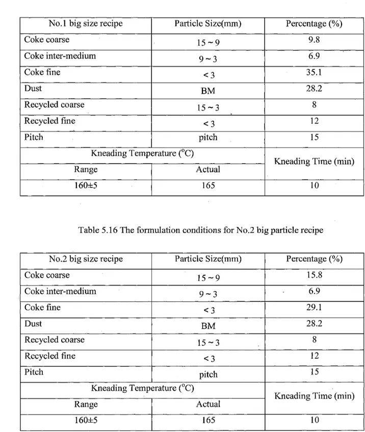
5.15 The formulation conditions for No. 1 big particle recipe 64 5.16 The formulation condition of No.2 big particle recipe 64 5.17 The formulation conditions for No.3 big particle recipe (base 65
recipe)
5.18 The properties of anodes prepared with big particle recipes 65 5.19 Comparison of properties for different groups 66 6.1 The results of TGA tests 74 6.2 The cumulative results of five baking tests 91 6.3 Summary of kinetic analysis results 91
Introduction
1.1 Background
Aluminium is produced by electrolysis, and the anodes used for this process are made of carbon. Low carbon (anode) consumption is very important for the aluminum industry which directly affects the cost of production as well as the environmental emissions. The anode consumption is strongly influenced by the properties of anode. In aluminum electrolysis, the study of carbon anode manufacturing and the improvement of its production techniques lead to savings in energy and reduction in gaseous emissions for the aluminum company[1"2].
The role of this international collaboration project is to pioneer the establishment of a research partnership between UQAC, GNU (Guizhou Normal University), and CHALCO (China Aluminum Corporation) in the aluminum technical development field. In addition, this project also aims to create a successful collaboration model called "2+1 partnership": one Canadian university + one Chinese university + one enterprise. In this model, all of the three parties use their expertise to turn the research, development, and manufacturing trinity into a successful reality. This partnership model has already been approved by the Guizhou province government.
In China, the low carbon consumption economy is a policy to improve the sustainable development. With new economy stimulus plan, states' governments seek to accelerate economic restructuring and desire to make substantial progress in transforming the economy from the extensive system to the technology-focused system. Therefore, all the aluminum companies give importance to energy saving, the reduction of carbon dioxide and other harmful gases during the production process as well as cost reduction, which are clearly linked to the improvement of anode quality. However, Chinese carbon plants have to deal with the raw material deterioration and multiple sources of petroleum coke acquisition at the same time. In addition to the transition from extensive production to technology-focused production, some problems such as equipment aging, high energy consumption, and high operation costs always accompany the technology upgrade of Chinese carbon plants.
The challenge for carbon plants is to produce a consistently high quality product regardless of changes in the actual circumstances and to cope with such variability [3"4].
During the industrial carbon anode manufacturing processes, raw materials play an important role in determining the final product (anode) properties, and the aluminum industry has to deal with the declining quality of the available petroleum coke around the world. Thus, today more and more industries, internally or through collaborative research projects with universities, seek ways to at least maintain the quality of anodes at the current level even under variable raw material conditions.
important role in determining the final product (anode) properties. Higher baking temperatures require higher energy consumption. In Chalco Guizhou branch, anodes are baked in the open-type horizontal baking furnace. Such furnaces are very large and necessitate significant fuel consumption. Anodes are placed in pits, stacked in layers from bottom to top, and are surrounded by packing coke. The hot gas in the horizontal flues, heated by heavy oil as well as the combustion of volatiles released during baking, provide the energy for baking. The consumption of fuel is in the order of more than three million Canadian dollars each year. As the world crude oil prices increase, the cost of production keeps rising^.
In recent years, companies found ways to lower fuel consumption. Better use of the heat content of the binder pitch volatiles is one of the best options for Chalco plant. Theoretically, based on the energy requirement for anode baking, the heat the pitch volatile combustion could provide is more than the amount of heat needed to bake the anodes. Within the flue gas temperature range 200°C to 800°C, anode temperature is increased to around 500°C. Between the temperatures 300°C and 600°C, pitch volatiles, mainly the condensable gas (tar) and non-condensable gases (H2 and CH4) are released from the
anodes. Then, the volatiles are drawn, under the negative pressure, into the flue in order to provide the energy for anode baking where the temperature of flue is high enough to burn them almost completely. This way, a certain amount of energy could be saved; in the mean time, the quality of products could be maintained by the high temperature level [6"8].
For optimizing the anode properties (air permeability, air reactivity, and CO2 reactivity), first, it was necessary to know the industrial anode production process and its operating system. This would facilitate the assesment of the steps which need improvement and to focus the work along with the results of this assessment. The results of the sampling and testing of the raw materials (coke and pitch), dry aggregate and recycled butt indicated which parts of the process needed attention. The anode quality optimization was based on a large number of single-factor experiments in order to adjust the specific production processes at the laboratory scale. The different production formulations, conditions, and parameters were tested repeatedly. Depending on the results of the series of anode formulation experiments, the anode recipe which yield the best anode quality was used in the second part. The correlation between the baking conditions and anode properties were studied in order to find the baking conditions which will improve anode properties further. Also, experimental results helped identify the anode baking conditions that would lead to energy saving during baking via the volatile release characterisation. Finally, the technical results and findings were implemented in the plant operation after the necessary technology transfer.
Anode quality is affected by the anode recipe and the anode baking conditions. The studies are very important on the both categories. In this study, a scanning electron microscopy and energy dispersive X-ray spectroscopy (SEM-EDS) were used in order to optimize the anode recipe. Then, the most costly anode manufacture process - anode
reactivities and air permeability were measured to evaluate carbon anodes in this research because not only they relate to anode density but also to anode consumption. This helped assess the potential for saving energy and reducing CO2 and hazardous gas emissions of the carbon production process.
Upon correlation with the results of anode formulation tests, the sample which has the best properties was chosen to simulate the baking process in the laboratory, and the gas produced (tar, H2 and CH4) was analyzed. Their amounts were also calculated not only to
be able to find the conditions to improve the quality, but also to determine the possibility of using the condensable (tar) and non-condensable gases (H2 and CH4) to reduce the energy
consumption and to improve the furnace efficiency.
1.4 Objectives
The global objective of the project is to improve the quality of the presently used carbon anodes. The raw materials used during anode preparation were analyzed by taking the local conditions into account in order to optimize the anode formulation. The relation between anode recipes and the anode properties such as CO2 reactivity, air reactivity, and air permeability were studied. The specific objectives are:
1. Test the properties of anode such as CO2 reactivity, air reactivity, and air permeability for different paste formulations and anode baking conditions.
3. Analyse the kinetics of devolatilisation of condensable and noncondensable gas for each anode baking condition.
Literature review ,
2.1 Anode Manufacture Process
During pre-baked anode manufacturing process, normally there are four basic steps:
Raw material handling;
Dry aggregate preparation;
Preheating, mixing, and paste cooling;
Forming and anode cooling.
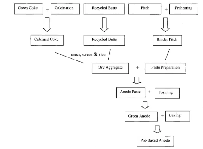
The calcined coke and recycled butts are crushed, screened, and sized to prepare the required size distribution and are mixed to form a dry aggregate. This aggregate is then preheated to between 110°C and 165°C and mixed with around 15 wt% pitch at a temperature between 150°C and 230°C. This process is called the 'anode paste preparation' and the result is the 'anode paste', which is then formed into an anode block either by pressing or vibratory compaction. Then, the 'green anode' is cooled and stored for baking[10]. After baking, the pre-baked anode is ready to be used in the electrolysis cell. A
Calcined Coke Recycled Butts Binder Pitch
crush, screen & size
Dry Aggregate Paste Preparation
Anode Paste Forming
Green Anode Baking
Pre-Baked Anode
Figure 2.1 The pre-baked anode manufacturing process flow diagram of Chalco plant
2.2 Raw Materials
Carbon anodes are manufactured from three raw materials; petroleum coke, pitch, and recycled materials (butts, baked and green scrap). Coke and pitch are required in large quantities. These are stored and mostly prepared separately[12].
Petroleum coke
The properties of incoming coke depend on the material source. Coke quality is defined as the combination of chemical and physical properties that influence the
performance of anodes manufactured from it. Typical coke characteristics are shown in the Table 2.1[10] and Table 2.2 [11].
Table 2.1 Green coke properties (Worldwide)
Property Water Content
Bulk Density Grain Stability
Specific Electrical Resistance CO2 Reactivity Loss (1000°C) Air Reactivity 525°C Ash Content Elements S V Ni Si Fe Al Na Ca Mg Method DIN 51304 ISO DIS 10236 ISO DIS 10142 ISO DIS 10143 ISO N802 ISO N803 ISO 8005 ISO N 837 ISO N 837 ISO N 837 ISO N 837 ISO N 837 ISO N 837 ISO N 837 ISO N 837 ISO N 837 Units % kg/dm3 % juflm % %/min % % ppm ppm ppm ppm ppm ppm ppm ppm Range 0.0-0.2 0.78-0.84 75-90 460-540 3-15 0.05-0.3 0.10-0.20 0.5-3.5 30-350 50-220 50-250 50-400 50-250 30-120 20-100 10-30
Table 2.2 Green coke properties (Chalco, Qinhai branch) Property Volatile Content Ash Content Elements S V Ni Si Fe Na Ti Units % % % ppm ppm ppm ppm ppm ppm Range Coke A 15.9 0.37 1.62 437 156 269 215 33 13 Range CokeB 13.2 0.38 0.46 <20 464 102 216 104 8
Comparing the green coke properties of a worldwide typical coke (Table 2.1) and those of Chalco Qinhai branch's coke (Table 2.2) revealed that CO2 reactivity and air reactivity measurements were not carried out in Qinhai branch.
Calcination:
Calcination is a thermal process in which green petroleum coke is heat-treated to 1200°C -1250°C. During calcination, moisture and volatile matter (such as hydrogen, methane, and tar) are removed. If not removed, these components might lead to cracking of anodes during the baking process due to shrinkage and coke devolatilisation. Cokes with significantly different volatile contents (quality and quantity), microstructure and/or
impurity levels must be calcined differently to obtain the optimal coke quality1^. Coke
undergoes structural changes during calcination, which improve properties such as crystalline size and real density[5]. Calcining is important to[12]:
1. achieve sufficient grain strength for handling;
2. minimise grain shrinkage;
3. ensure that the pore structure is accessible to binder pitch.
The most important calcining parameters for the petroleum coke quality are temperature, throughput, and residence time[13"14]. The final calcination temperature and
residence time together determine the final real density of the calcined coke. The heating rate during calcination influences porosity as increased rates result in more rapid volatile evolution [15-17].
Pitch:
Pitch used for anode manufacturing is made from the distillation of high temperature coal tar petroleum that is a residue of petroleum refining industries [18]. Many researchers
determined that the binder-matrix (mixture of dust and pitch) would be oxidized at first by air or CO2 reaction. This is called selective oxidation[19]. Hence, optimizing the pitch
content is important for pre-baked anode manufacturing[20"21]. Typical properties of pitch
Table 2.3 Pitch properties (Worldwide) Property Water Content Softening point Density in water Coking Value Quinoline Insolubles Toluene Insolubles Ash Content Elements S Na Ca Si Fe Zn Pb Method ISO 5939 DIN5 1920 ISO 6999 ISO 6998 RDC 171 ISO 6379 ISO 8006 Units % °C kg/dmj % % % % % ppm ppm ppm ppm ppm ppm Range 0.1-0.2 110-115 1.3-1.33 56-60 7-15 26-34 0.1-0.2 0.3-30.6 10-400 20-80 50-200 50-300 100-500 100-300
Table 2.4 Pitch properties (Chinalco, Qinhai branch)
Property Softening point Volatile Content Coking Value Quinoline Insolubles Toluene Insolubles Ash Content Method DIN5 1920 -ISO 6998 RDC 171 ISO 6379 ISO 8006 Units °C % % % % % Range 110 54.8 59 14.9 31.5 0.67
Scrap:
Green and baked scrap is fed back into dry aggregates. Green scrap is generated from start-up/shutdown operations or changing process conditions within the plant. Green scrap is included in the anode recipe in quantities of up to 5%. Baked scrap such as rejected baked anodes is also often included in the recipe in small quantities and is processed with the butt component. Both green and baked scrap is usually stored in flat pots or bins[22"25].
Butts:
The butts are cleaned up from adhering impurities (bath material) and are then crushed, screened, sized, and mixed with the dry aggregate for use in anode production. The formulation for the new anode can contain up to around 30% of crushed butts. The quality of the butts can influence the quality of the anodes. The butts contain catalytic bath material hence adversely affect the reactivity of the new anodest26~29].
2.3 Anode Baking Process
Anode baking process consist of four different parts: preheating, heating, forced cooling and natural cooling. Figure 2.2 shows the overview of Chalco's anode baking process[30-33].
Preheating
In the first 3 section of Figure 2.2, the flue gas temperature which varies from 200°C to 900°C increases the anode temperature from ambient temperature to around 550°C.
Between 200°C and 600°C, pitch volatiles start to evolve from the anode. These volatiles are drawn under the negative pressure into the flue (through the refractory wall openings) where the temperature is high enough to burn them.
Heating
In the next 3 sections, typically the gas temperature is raised up to around 1150°C by the combustion of fuel. Using the gas injectors which are installed on the burner ramps, the fuel can be injected into the flue. In this part, the anode temperature reaches a target temperature from the preheating temperature of around 550°C to the final temperature 1050°C in the Chalco plant. There is also a soaking period. During preheating and heating, the mechanical, physical, and chemical characteristics within the anode vary. The baked anode properties are affected significantly by the baking conditions.
Forced and Natural Cooling
In the next zone (3 sections after the heating section), a cooling fan seeks to provide enough oxygen for combustion in both the preheating and heating zones. And also the air has been preheated by the heat recovery from the refractory and anodes. Following these three sections, a cooling zone without heat recovery further lowers the temperature of anodes and the packing coke.
Exhaust manifold Measuring ramp Burner ramp Cooling fan
n
airw
w
Preheating zone Heating zone Cooling zone Figure 2.2 The baking process overview
During the baking process, the preheating zone is where the burning of the pitch volatiles takes place. Thus, utilizing the right timing of ignition temperature and the required oxygen content to maximize volatile combustion in the baking furnace became a popular research field in the recent years[34].
2.4 Anode baking optimization
The main baking conditions which relate to anode quality are anode heating rate, maximum baking temperature and soaking time[35"37].
The heating rate is related to anode flexural strength and electrical resistivity. If anodes are heated up too fast, it will cause those anodes to crack. The micro-cracks may start inside the anode gradually during the baking process, and then series of cracks forming from the internal part of the anode to the surface might yield the splitting of anode.
The maximum baking temperature affects the CO2 reactivity, air reactivity and
thermal conductivity. Higher maximum temperatures decrease CO2 reactivity, air reactivity
and increase thermal conductivity. In most cases, excessive thermal conductivity might cause air burn at the anode top. Thus, the control of maximum baking temperature is important for the optimization of the anode quality and the prevention of anode overbaking.
Soaking process is the last step of anode heat treatment. The major target of soaking is to heat the anodes which are placed at the different positions evenly. The longer soaking times result in better uniformity of anode properties.
2.5 Pitch volatiles
Typically, in the carbon plant, the temperature of anode baking is always less than the temperature of coke calcination. The volatiles released from the anodes during the baking process come from the pitch, thus called pitch volatiles. There are two parts of pitch volatiles, non-condensable gas and condensable gas. Three main components of these gases are hydrogen and methane, which represent the non-condensable part, and tar, which represents the condensable part. Tar also includes polycyclic aromatic hydrocarbons (PAH). PAHs with six or less combined aromatic rings are known as 'small PAHs', and those containing more than six aromatic rings are called 'large PAHs'. The PAHs of pitch volatiles are mainly of 'small5 PAHs type. [38"39]. The composition of the tar component was
According to the energy balance, the heat the pitch combustion could produce actually is more than that needed for anode baking energy consumption. In other word, increasing the pitch volatiles combustion not only reduces the costly fuel consumption down to a minimum, but also achieves clean production.[4(M1].
Chapter 3
Experimental
3.1 Introduction
In this project, first an investigation has been carried out on raw materials in order to optimize the anode recipe. This part involves a review of production process in order to determine the problem points in the plant followed by the anode production with different particle size distributions. The relationship between the anode formulations and anode properties (permeability, air reactivity, and CO2 reactivity) were studied. This part was carried out at the Chalco plant in Guizhou, China. Then, a study on kinetics of anode baking is carried out at UQAC. In this part, the anode formulation that yielded the best properties in the previous part was chosen to simulate the baking process in the laboratory. The devolatilisation (tar, H2, and CH4) kinetics were investigated. Again, the anode
properties were measured after baking the anodes under different conditions. This serves to determine the conditions that lead not only to improved anode quality but also more efficient utilisation of released volatiles to reduce the energy consumption. A schematic diagram of the experimental plan is shown in Figure 3.1. Via repeated trials following the experimental procedure, different production formulations, conditions, and parameters were tested and improved. The results were transferred to the plant for implementation in the plant operation.
Data Analysis
I
Anode preparation1
1
8
I
Analysis of Volatiles Information feedbackSample mixing & forming
Samples Baking & Cooling
i
Baked Anode
CO2 reactivity testing Air reactivity
TGA System Analysis
Green anode samples
Data Analysis
Air permeability
3.2 Experimental Set-up
3.2.1 Equipment for anode preparation in laboratory:
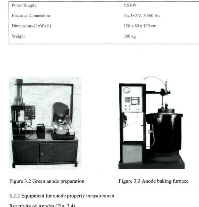
Bench Scale Unit for Green Anode Preparation (Fig. 3.2,)
The bench scale unit (R&D Carbon RDC 161) for green anode preparation consists of a kneader and a press. Anode formulation studies require the adaptation of the pitch level as well as the adjustment of the particle size distribution, which necessitate a large number of tests'-42"431. Table 3.1 shows the specifications of this unit.
Table 3.1 Specifications of of green anode preparation bench scale unit
Power Supply Electrical Connection Dimensions (LxWxH) Weight 9kW 3 x 380 V, 50/60 Hz 130x110x213 cm 1100 kg
Anode Baking Furnace (Fig. 3.3)
The R&D Carbon RDC-166 anode baking furnace was used for the baking of the green anodes. The furnace simulates the industrial process. The green anodes are placed in the furnace and surrounded by packing coke. These trials serve to maintain the quality raw material selection and to ensure the quality control of pre-baked anodes^4"451. Table 3.2
Table 3.2 The specifications of baking furnace Power Supply Electrical Connection Dimensions (LxWxH) Weight 5.5 kW 3 x 3S0 V. 50/60 Hz 120 x 80 x 179 cm 300 kg
Figure 3.2 Green anode preparation Figure 3.3 Anode baking furnace
3.2.2 Equipment for anode property measurement Reactivity of Anodes (Fig. 3.4)
Carbon reacts with carbon dioxide according to the endothermic reaction:
This reaction always takes place in the electrolysis cell. In aluminum production where electrolytic cells operate at 950-960°C (1745-1760°F), carbon dioxide, generated at the anode interface by electrochemical oxidation, can attack the carbon anode via this reaction. The total weight loss which is equal to the difference between the original sample weight and final weight after reacting with CO2 is the CO2 reactivity percentage (%) residue^46"47-1. Table 3.3 shows the standard used and the specifications of the equipment.
Table 3.3 The specifications of CO2 reactivity test
ISO Method Power Supply Electrical Connection Gas Supply
Gas Connection Gas Flow Rate Gas Quality
Furnace Heat-up Time
Furnace Temperature (during test) Vapours Emitted
Test Time (excl. sample preparation) Number of Samples/Test Sample Length Sample Diameter 12988-1 2.0kW/6.0kW 2Lx380 V / 3x380 V - 50/60 Hz
CO2 ; adjusted to 2 bar on manometer
Tube: External Diameter 6 mm, Internal Diameter 4 mm, must withstand 10 bar
200 1/h, min. 3 bar CO2 better than 99,5%
Appr. 2 hours from room temperature to 960 Deg C 960 °C
CO (Carbon Monoxide) 9.5 h for 2 samples in 1 furnace two
60 mm 50 mm
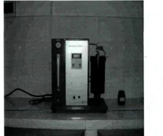
Air Reactivity of anode (Fig. 3.5)
During aluminum electrolysis, the air-burn causes the anode consumption and increases the temperature of the upper surface. Following two reactions are possible since the anode upper surface temperature is generally between 550°C and 650°C:
C + O2 = CO2 (3.2)
(3.3)
The air reactivity can be measured by using the R&D Carbon RDC 151 apparatus. After the reactivity tests, the samples are cooled from 550°C to 400°C with cooling rate of 15°C /h. After cooling and weighing, the samples are mechanically tumbled with steel balls in a separate piece of equipment (R&D Carbon RDC-181, tumbling apparatus) to remove any loosely-bound particles. The total weight loss equals the difference between the original and final sample weight and is presented as the air reactivity percentage (%) residue1-48"49^. Table 3.4 shows the standard used and the specifications of the equipment.
Air Permeability (Fig. 3.6)
The gas permeability of the material has a great influence on both CO2 and air
reactivities. A high permeability leads to increased reactivity since CO2 or air can penetrate
into the anode which increases the anode consumption even further. The gas permeability of anodes were measured using the R&D Carbon RDC-145 apparatus. The permeability is determined by measuring the time that a gas needs to pass through a sample in order to refill a partly evacuated system. The sample has a disc shape with a diameter of 50 mm and
a length of 20 mm [50"51]. Table 3.5 shows the standard used and the specifications of the
equipment.
Figure 3.4 CO2 reactivity of anodes Figure 3.5 Air reactivity of anodes
ISO Method Power Supply Electrical Connection Gas Supply
Gas Flow Rate Gas Quality Vapours Emitted
Table 3.4 The conditions of air reactivity test
12988-2 L l k W / 3 . 3 k W
2 L x 380V / 3 x 380 V - 50/60 Hz Air ; set to 2 bar on manometer 200 1/h min. 4 bar
Air, N2 : 78%, O2 : 21%, Ar : 1%, H2O < 150 mg / Nm3, free of oil
CO2
Test Time (excl. sample preparation) 11.5 h for 1 sample Number of Samples/Test two
Sample Length 60 mm Sample Diameter 50 mm
Table 3.5 The specifications of air permeability test
ISO Method Power Supply Electrical Connection Air Pressure Setting (1)
Test Time (excl. sample preparation) Number of Samples/Test Sample Length Sample Diameter 15906 0.5 kW 220 V, 50/60 Hz 2 bar Appr. 2 minutes one 20 mm 50 mm
3.2.2 Equipment for Devolatilisation Kinetics Measurement :
Thermogravimetric Analyser (TGA) Coupled with Gas Chromatograph (GC)
Figures 3.7 to 3.11 show different parts of the system, and Figure 3.12 shows the flow diagram.
Thermogravimetric Analyser (TGA)
The sample was tied by metal wires and then suspended from a balance for measuring the weight loss of anode sample during baking. The nitrogen gas was used as the carrier gas and protection gas for both TGA and gas chromatograph. The carrier gas nitrogen enters the furnace from the bottom. Rotameters R23 and R13 control the gas fiowrate. The carrier gas flowrate is not only important for the success of anode baking test but also important for the calculation of the amount of each volatile. During baking, part of the gas with a known flowrate was suctioned for analysis with GC. Both the main outlet gas and GC sampling gas was passed through a cold trap in order to separate the tar. In the cold trap, cold water with a temperature less than 4°C was recirculated. This prevents the blockage of the connection tubes and rotameters, thus, protects both TGA and GC system efficiently and make this system work well.
It can be seen from the figure 3.12 that the gases for analysis (red line) pass through the condensable tank, glass wool filter and the rotameters Rl, R2 and R3. An automatic controller ensures the injection of gas for analysis. At that time, the valve Q3 closes, then Ql and Q2 open automatically and the sampling gas trapped in the injection coil flows in to
the column. After GC injection, Ql and Q3 close, Q2 opens, the gas goes out directly due to suction. The rest of the outlet gas is pumped out by Pump 1A and Pump IB continuously.
Figure 3.7 Coupled TGA-GC analyzer
Figure 3.8 TGA controller Figure 3.9 Cold trap
Automatic controllor forQl,Q2,Q3
Gas flow to GC:
Gas coming out from GC: Purge gas:
Gas out: Cooling water: Carrier gas flow: Air flow:
Gas Chromato graph (GC)
The nitrogen gas was used as the carrier gas for the GC (Varian 3800) analysis. Compressed air was used for the injection valve operation. A known volume of sample gas was stored in the injection cycle and injected into the column with the help of this valve. An injector type 1061 was used. The column was packed with 13X molecular sieve. This type of column can separate hydrogen and methane well. After the injection, the column adsorbs all the gases, and desorbs each gas separately. GC was equipped with thermal conductivity detector. The thermal conductivities of the sample gas mixture were compared with that of the carrier gas which was flowing on the reference side of the detector. The Wheatstone bridge arrangement was used for the TCD measurements[51"53]. Through the
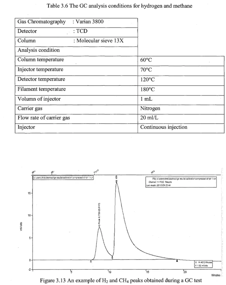
calibration of thermal conductivity vs. the gas concentration for each gas, their concentrations were determined from the areas of the desorption peaks. Table 3.6 shows the details of GC conditions for the gases analysis.
An example of hydrogen and methane peaks obtained during the experiments is displayed in Figure 3.13. This figure shows that H2 and CH4 peaks were separated quite well during the gas chromatograph test. The peak of methane always appeared after that of hydrogen.
Table 3.6 The GC analysis conditions for hydrogen and methane
Gas Chromatography : Varian 3800 Detector : TCD
Column : Molecular sieve 13X Analysis condition Column temperature Injector temperature Detector temperature Filament temperature Volumn of injector Carrier gas
Flow rate of carrier gas Injector 60°C 70°C 120°C 180°C l m L Nitrogen 20 ml/L Continuous injection Minxes Figure 3.13 An example of H2 and CH4 peaks obtained during a GC test
Figure 3.14 and Figure 3.15 show the calibration curves of hydrogen and methane. They both gave high correlation factors (R2).
y = 0,0042x R2 = 0,9948
200 400 600 800
Hydrogen concentration, ppm
1000 1200
Figure 3.14 The calibration curve of hydrogen
0) 03 O CL 4 3,5 3 2 , 5 1 5 1 0,5 0 -y = R2 = 1 0,004x ^ S ^ 0,9914 ^ y ^ 1 l 1 1 200 400 600 800 1000 1200 Methane concentration, ppm
3.3 Methodology
3.3.1 Characterization and analysis of raw material
The raw materials used in anode production were tested for the trace elements content using Chinese Nonferrous Metals Industry Testing Standards YS/T 587[30]. These raw
materials were analyzed using SEM-EDS. Samples were treated and polished using ASTM D 2797[32].
3.3.2 Anode formulation experiments
The anode formulation experiments were separated into two groups. The small particle group for which the maximum particle size was less than 12mm was marked group A. The big particle group which had the particle sizes larger than 12mm was marked group B. In each group, different recipes were tested to determine the effect of each size fraction. Finally, a recipe which resulted in best anode properties (air reactivity, CO2 reactivity, and air permeability)[32] among those tested was chosen for further analysis.
3.3.3 Thermogravimetric experiments and volatiles analysis
Small anode samples were prepared based on the best recipe obtained from the anode formulation experiment with the raw materials available in the Guizhou province of China using the same procedure followed by the industry. These anodes were baked in a thermogravimetric analyzer. The effects of the following baking parameters on the anode properties (CO2 reactivity, air reactivity, air permeability) were studied and correlated with anode preparation conditions.
• Heating rate • Soaking time • Baking temperature
Anode quality (properties) were also correlated with anode preparation conditions. Gas devolatilisation analysis was carried out. Kinetic parameters were determined for differen baking conditions.
3.4 Model for devolatilization kinetics
During the baking of green anodes, tar, CH4, and H2 are produced due to the cracking
of pitch volatiles. The kinetics of formation of tar, CH4, and H2 can be determined using the
thermogravimetric analysis coupled with the gas chromatography. In this work, the kinetic parameters were calculated using the model developed by Kocaefe et alJ16] assuming that
H2, CH4, and tar form. It was assumed that devolatilisation of each component follows nth order rate equation of the form:
(3.4)
^ k,cr^x,y
atXii conversion of component i (i denotes H2, CH4 or tar)
n : order of reaction
ki: rate constant for gas i (s"1 concentration1"11)
It is further assumed that the rate of devolatilization is dependent on the temperature and follows the Arhenius law.
(3.5)
ki0: Pre-exponential factor for gas i ( s1 concentration1"11)
E: activation energy [J/mol]
R: gas constant [8.314 J/mol K]
T: Temperature [K]
In this work, the activation energy, rate constant, and the order of the reaction for all the formation reactions were determined by the differential method.
3.4.1 Determination of kinetic parameters
Here the basis of calculation for the determination of kinetic parameters for the formation of H2, CH4, and tar is described. As there is no gas chromatography data available for tar, the instantaneous weight loss due to this component was found from the difference between the instantaneous total weight loss and the instantaneous weight loss due to H2, CH4 calculated using the GC data. After the calculation of the instantaneous rate of tar, the method of calculation of its kinetic constants is the same as those of H2 and CH4.
Below, the general method for the calculation of kinetic parametrs is explained.
Using the chain rule given below (Equation 3.6),
combining the Equations 3.4, 3.5 and 3.6, defining the heating rate (h=dT/dt), and taking the logarithms of both sides give:
In dX,
Y
/dtRT (3.7)
where apparent pre-exponential factor is defined as
kiO,aPP=kioCtX) (3-8)
The following Figure 3.16 gives an example of tar kinetic parameters determination by plotting In (dXi/dT / (1-Xj) n) vs. 1/T (see Equation 3.7). The best line is determined.
Data were plotted using different n values and the one that gives the best linear relationship (best R2, correlation coefficient) was taken as the solution.
X
_ l/T
3.4.2 Determination of conversion (X) for each gas component
A part of the outlet gas was withdrawn for analysis. Then, its methane and hydrogen content was analysed using a gas chromatograph equipped with a thermal conductivity detector. The detector response was calibrated for methane, hydrogen, and oxygen using calibration gases of known concentrations. Data on oxygen was used to detect if there was any air leak on the line and correct the gas concentration if necessary.
1. Calibration: The objective of calibration of gas chromatograph response is to find the relationship between the peak area and its corresponding concentration of a given gas component. The area under the peak obtained was measured with the software of the gas chromatograph. Thus, dividing the known value of concentration (ppm) by the area obtained using GC, the concentration as- 'ppm per unit area (PPMA)' for the particular component can be calculated. Using different concentrations, the calibration curve was prepared to use later on in the TGA-GC measurements.
2. Calculation of concentration of a component:
The concentration of the component in ppm is equal to area of peak obtained by GC multiplied by PPMA for the component. However, the gas in the TGA always contains some air, i.e., air slightly dilutes the concentration of the component so the calculated ppm of the component is always less than the exact ppm on air-free basis. That is why the dilution ratio has to be determined and the correction has to be made.
By definition of ppm,
Y ppm of a gas = mole of the gas /106 mole of total (3.9)
For an ideal gas, 1 mole of the gas occupies a volume of 22400 ml.
The instantaneous mass flow rate of gas in g/min =
Y*M*(total flowrate in ml/min)/106*22400 (3.10)
where M is the molecular weight of the gas.
4. Instantaneous rate of total weight loss in g/min:
To determine the instantaneous rate of total weight loss in g/min, the weight loss vs. time curve is differentiated numerically. The slope of the curve at each time gives the instantaneous total weight loss in g/min.
5. Presentation of the instantaneous total weight loss per 100 g of anode sample:
As all the calculations are dependent on the weight of the sample, the calculation has to be made independent of the initial weight of the sample. Therefore, the data is represented on the basis of 100 g of sample. Thus, the instantaneous amount of gas in g/min per 100 g of sample is expressed as:
Instantaneous total weight loss of gas (g/100g of sample) =
6. The instantaneous methane and hydrogen release data are already available from the GC analysis. The difference between the total and the sum of hydrogen and methane gives the instantaneous tar release data.
7. Calculation of cumulative data per 100 g of anode sample:
The integration of the curve representing the instantaneous amount of gas component vs. time (the area under the curve) gives the cumulative data for all three components.
8. Calculation of conversion for the component:
The conversion is calculated by dividing the cumulative weight loss of a gas component at a particular time by total amount of weight loss for that component.
Thus the conversion for a species at a particular time is given by:
Conversion (t) = Cumulative weight loss for a species (t) / Cumulative weight loss for that species (3.12)
Chapter 4
Characterization and analysis of raw material
4.1 Introduction
For optimizing the anode properties (air permeability, air reactivity, and CO2 reactivity), first it was necessary to do an investigation in the Chalco plant in order to understand their anode production process and their operation. This was necessary for assessing the key points that could be improved as soon as possible and aligning the research project along with the results of this assessment. The results of the sampling and testing of the raw materials (pitch, dry aggregate which consists of coke, recycled butt and anodes) indicate which parts of the process need attention and help better focus the work. The anode quality optimization was based on a large number of single-factor as well as orthogonal experiments in order to adjust the specific production processes at the laboratory scale. The different production formulations, conditions, and parameters were tested repeatedly. Finally, the results of this project was implemented in the plant operation after the necessary technology transfer.
In this chapter, a review of the anode production process, from the raw material storage yard, raw material transportation lines, calcination kilns, calcined coke cooling kilns, the green mill to the forming system was carried out. Each part had been visited, pictures and samples were taken in order to determine which part needs the most attention. The results are summarized in the following section.
4.2 Results
4.2.1 Investigation of green anode manufacting process
The coke is transported to the plant by train. At first, it is piled in the outside yard, waiting to be transported by trucks and scrapers into the storage. Then, it is passed through a crush line called a "pre-crush" process to adjust the coke particle size before the raw material is fed into the calcination kilns, (see Figures 4.1 to 4.4).
Figure 4.1 Coke pile in the outside yard Figure 4.2 Coke transportation
After the *'pre-crush" process, the "pre-crushed" coke is moved into the calcination kilns by a conveyor.
Calcination
During the calcinations process, the green coke is calcined in large kilns up to 1200°C with the gas temperature around 1500°C. In the plant, the kiln is divided into three parts for the control of the calcination temperature. The part which is connected to the feeding bin is called the "tail", the temperature of this part is the lowest. The middle of the kiln is called the "body" at the highest temperature. The exit of the kiln is called the "head" at the medium temperature. Thus, the calcination takes place mainly in the "body" section. Afterwards, the calcined coke is fed into a cooling kiln to lower the temperature of the coke (see Figures 4.5 and 4.6).
Green Mill and Forming
Before mixing and forming, all the raw materials are crushed, screened, and sized according to predetermined size distribution and added together to form a dry aggregate. This aggregate is then preheated to around 165°C and mixed with 15 wt% liquid pitch that is preheated to a temperature between 150°C and 180°C. Then, the anode paste is formed into a green anode block by the vibratory compaction (Figure 4.7).
Figure 4.7 Vibratory compaction unit
Recycled Anode Clean-Up
The butts which are fed as part of dry aggregate are cleaned by removing the adhering impurities (bath material, see Figures 4.8 and 4.9) and are then crushed, screened, sized to
two fractions (coarse 3-12mm and fine < 3mm ), and transported into the aggregate for
-# J s ••
^ I
Figure 4.8 Recycled anode butts Figure 4.9 Automatic shoot penning equipmentfor butts clean-up
In the new anode recipe, a recycled anode can be between 20% to 25%. The quality of the butts can influence the quality of anodes. The butts contain catalytic bath material hence adversely affecting the anode reactivity.
After visiting all the production units, the experiments were started in the laboratory. There were a number of findings which pointed out some of the challenges in the production process during the review; and these are summarized in the following part.
4.2.2 Preliminary Experiments:
At first, all the samples which were taken from different parts of the anode production process were tested and analyzed for trace elements using SEM methods.
Trace Elements Testing
The trace element testing method is based on YS/T 587- Chinese Nonferrous Metals Industry Testing Standards. Tables 4.1 to 4.3 summarize the results.
Table 4.1 Water and S contents of the cokes 1# Green Coke 2# Green Coke 1# Calcined Coke 2# Calcined Coke 3# Calcined Coke 4# Calcined Coke 0# Calcined Coke Pitch Water Content (%) using standard YS/T 587 2006
1.00 0.54 0.12 0.13 0.13 0.14 0.04 -S content (%)
using standard YS/T 587.4 2006 2.10 2.12 1.70 1.73 1.65 1.70 1.30 0.30
Table 4.2 Trace elements of raw materials
Sample l#Calcined coke 2#Calcined coke 3#Calcined coke 4#Calcined coke Green coke Pitch Units ppm ppm ppm ppm ppm ppm Fe 1160 1520 700 720 300 450 Ca 1590 1690 1630 480 210 640 V 150 180 120 170 170 60 Si 11600 4100 13500 2500 4600 5600 Na 350 430 260 320 138
Table 4.3 Trace elements content of sized cokes and paste Sample Coarse Fine Recycled coarse Recycled fine Dust Anode paste Units ppm ppm ppm ppm ppm ppm Fe 525 491 4352 1457 701 598 Ca 2490 2211 1703 1681 1842 1913 V 333 260 145 350 108 235 Si 7860 3200 2300 7350 5380 4380 Na -1320 2796
-Among the results, especially four elements reflect the raw materials9 characteristics
used by Chalco. The vanadium content is normal, but the Fe, Ca, Si, and Na contents are too high and they affect seriously the properties of the anode reactivity. The SEM analysis was carried out to investigate the morphology of the metal impurities. The results of SEM analysis is presented below.
SEM Analysis
The samples of calcinated cokes, anode paste, baked anodes, and recycled anodes were treated and polished using ASTM standard D 2797. The findings of SEM and EDS analysis are explained below.
100|jm ' i f l i 1
Figure 4.10 Image of anode paste
The Figure 4.10 shows the wetting and penetration behavior of the binder-matrix (mixture of dust and pitch). At optimum conditions, the pitch/fines binder matrix penetrates the fissures and pores of the coarse petroleum coke particles and thinly coats these particles154"551.
SEM-EDS image showed the presence of La and Ce. Figures 4.11 to 4.18 show these elements in different materials. Arrows shown on SEM micrographs of the figures below points to the positions of these rare earth elements, La and Ce, which were found in the calcined coke A, recycled butt A, and anode A. Anode A has coke particle sizes less than 12mm as explained in Chapter 3 whereas Anode B contains larger coke particles.
Figure 4.11. SEM images of coke A
Figure 4.13.SEM images of
carbone anode A
Figure 4.15. SEM images of carbone anode A
Figure 4.12. EDS patterns of the La element in coke A 5000- 4000- 3000- 2000- 1000-K Ca 0 Ca ^ K L a i 0 2 4 6 « 1 8 5714 ds J Ï S 0 TO 3 10 12 H 16 Si 2 8 20 keV
Figure 4.14. EDS patterns of the La element in
carbone anode A
ilil;
Ue Ce
l i l g 1076 ds i t f i 19 647 (Ods)
8 10 12 14 16 16 20
Figure 4.16. EDS patterns of the Ce element in carbon anode A
Figure 4.17.SEM images of
recycled butt A
Figure 4.18. EDS patterns of the La element
in recycled butt A
Figures 4.12, 4.14, 4.16, 4.18 show the difference in La and Ce quantities present in raw materials and anodes. Figure 4.11 illustrates that calcined coke containing La has a rough surface with pores and cracks. The structure of La particles is granular. Figures 4.14 and 4.16 show the presence of La and Ce in the anode samples. Both of elements seem to be flat and stuck on the surface of the sample. Figure 4.18 shows the presence of La in the recycled butt. The structure of La particle is flat and stuck on the surface of recycled butt, similar to the anode sample. Figures 4.11, 4.13, 4.15, 4.17 show the distribution of the elements at the point where arrows are pointed. As it can be seen from these figures, the La and Ce coexist with the Al, Na and Si. From the analysis, it can be said that the rare earth elements might exist in the green coke as well as in anode butts. During the anode manufacturing process, these elements are mixed into the anode paste.
1mm • % 7 - B t 1
Figure 4.19 Image of calcined coke
Figure 4.19 show that there are large amounts of pores inside the calcined coke due to release of volatiles during calcination. The analysis showed that these types of cokes are found in the anode paste. They may increase the porosity and air permeability of anode. Thus, the small particle size distribution anode (Anode A) was tested in the anode formulation experiments to increase the contact area of coke and pitch[56] and to decrease
the anode porosity.
4.3 Discussion of results
Three key results found at the end of the first series of experiments are as follows:
1. The impurities Fe, Ca, Si, Na are mainly trace elements in raw materials, intermediates and baked anodes, and these elements can greatly affect the anode reactivity. Thus, it
was suggested to the plant that these four elements are traced and controlled in the future production. However, the following question remains: how to decrease the contamination of raw materials and anodes during the production process? This problem will be addressed in the conclusions part.
2. The formulation of the anode paste was tested and adjusted and presented in the next chapter. The attention was given especially to the adjustment of the recycled anode content in the recipe because most of Na and Fe come from the recycled anode during the paste preparation.
3. The rare earth elements La and Ce were discovered in the raw materials, baked anodes, and recycled anodes. These elements will be continued to be followed. However, the effects of these trace elements are not within the scope of this work. They will be subj ect of a future proj ect.
4.4 Summary
The investigation on the production units and the first series of experiments have helped greatly focus the work. Some solutions have been suggested to the plant to improve their operation and manufacturing process.
1. Determining the trace elements (Fe, Ca, Si, Na) is a key control variable and their content should be used as an indication of the contamination during the entire manufacture process.
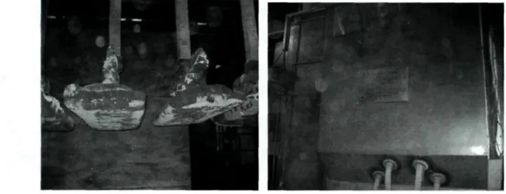
a) The inner lining of the calcinations kilns should be replaced regularly because the lining material can increase the Ca and Si of calcined coke (see Figure 4.20).
Figure 4.20 The lining material mixed with calcined coke
b) The cooling section of the coke calcination kiln should be fixed regularly because there is no lining inside the kiln; and the inner wall of the this part can easily get rusty and peel leading to increased Fe in calcined coke (see Figure 4.21).
Figure 4.21 The rust mixed with the calcined coke
c) The electromagnetic iron-separator above the transportation belts should be cleaned frequently because of the many captured iron wires coming from the raw materials and other parts of the production (see Figures 4.22 and 4.23).
Figure 4.23 The iron-separator (after clean-up)
3. Rare earth elements serve as catalysts in secondary cracking process of refining heavy oil. Thus the rare earth elements La and Ce are the residual impurities of petroleum coke. It was observed that the La and Ce coming from coke as well as from butts can accumulate in anodes during the anode manufacture process. The baked anode might contain higher La and Ce content than the raw material and recycled butts. The presence of La and Ce increases CO2 and air reactivities of
Chapter 5
Correlation between anode formulation and anode properties
5.1 Introduction
In Chapter 4, the characterization and analysis of raw material have been discussed. The properties of the currently used anodes were determined in order to correlate the current anode recipe and anode properties. As shown in Chapter 4, Figure 4.19 shows the type of coke structure found in the anode paste. This is likely to increase the porosity and air permeability of the anode. Thus, the quantity of small particle size fraction group with maximum particle size less than 12mm was adjusted in the paste formulation experiments to increase the contact area of coke and pitch and to decrease the effect of coke porosity. The correlation between anode formulation and anode properties is discussed in this chapter.
5.2 Results
5.2.1 The results of small particle size recipes
Tables 5.1 to 5.8 present the recipes (coke particle size distribution), pitch type, and kneading conditions used in anode formulation. As shown in these tables, the same pitch in same quantity (15% wt) and the same kneading conditions were always used. Only the percentage of coarse and fine particle fraction groups were changed. The formulation No 1 was taken as the reference recipe (Table 5.1). In the recipe 2, the percentage of coarse
fraction was increased (10-6mm) and that of the fine fraction was decreased ( < 3mm). In
3rd and 4th recipes, the largest diameter size was eliminated. 8-6 mm fraction was used instead of 10-6mm fraction. In the 3rd recipe, the same percentages as the 1st recipe were used. The only difference was the particle size range of the coarse fraction. In the 4th recipe, this fraction was increased wheres the fines were slightly decreased. From 5th to 8th recipe, the coarse fraction was completely eliminated. The percent of 6-3 mm fraction was taken as the total of 10-6 mm and 6-3 mm fractions for recipe No.7. For the others, this fraction was either increased (recipe No.5) or decreased (recipe No.6 and 8). The balance is corrected by adjusting the fine content.
Table 5.1 The formulation conditions for No. 1 small size recipe
No.l small size recipe Coke coarse Coke inter-medium Coke fine Dust Recycled coarse Recycled fine Pitch Particle Size(mm) 10-6 6-3 <3 BM 10-3 < 3 • Kneading Temperature (°C) Range 160±5 Actual 165 Percentage (%) 9.8 6.9 35.1 28.2 8 12 15
Kneading Time (min)
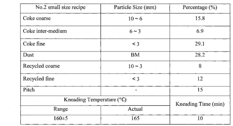
Table 5.2 The formulation conditions for No.2 small size recipe
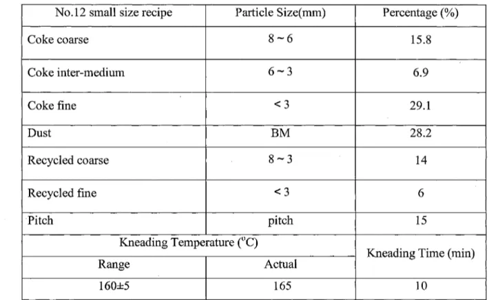
No.2 small size recipe Coke coarse Coke inter-medium Coke fine Dust Recycled coarse Recycled fine Pitch Particle Size (mm) 10-6 6-3 < 3 BM 10-3 < 3 -Kneading Temperature (°C) Range 160±5 Actual 165 Percentage (%) 15.8 6.9 29.1 28.2 8. 12 15
Kneading Time (min)
10
Table 5.3 The formulation conditions for No.3 small size recipe No.3 small size recipe
Coke coarse Coke inter-medium Coke fine Dust Recycled coarse Recycled fine Pitch Particle Size (mm) 8 - 6 6-3 <3 BM 8-3 < 3 -Kneading Temperature (°C) Range 160±5 Actual 165 Percentage (%) 9.8 6.9 35.1 28.2 8 12 15
Kneading Time (min)
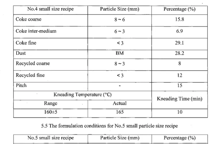
Table 5.4 The formulation conditions for No.4 small size recipe No.4 small size recipe
Coke coarse Coke inter-medium Coke fine Dust Recycled coarse Recycled fine Pitch Particle Size (mm) 8-6 6-3 <3 BM 8-3 < 3 -Kneading Temperature (°C) Range 160±5 Actual 165
5.5 The formulation conditions for No.5 small particle No.5 small size recipe
Coke inter-medium Coke fine Dust Recycled coarse Recycled fine Pitch Particle Size (mm) 6-3 < 3 BM 8-3 < 3 -Kneading Temperature (°C) Range 160±5 Actual 165 Percentage (%) 15.8 6.9 29.1 28.2 8 12 15
Kneading Time (min)
10 size recipe Percentage (%) 22.7 29.1 28.2 8 12 15
Kneading Time (min)
Table 5.6 The formulation conditions for No.6 small particle size recipe
No.6 small size recipe Coke inter-medium Coke fine Dust Recycled coarse Recycled fine Pitch Particle Size (mm) 6-3 < 3 BM 8-3 <3 -Kneading Temperature (°C) Range 160±5 Actual 165 Percentage (%) 15.8 36 28.2 8 12 15
Kneading Time (min)
10
Table 5.7 The formulation conditions for No.7 small particle size recipe
No.7 small size recipe Coke inter-medium Coke fine Dust Recycled coarse Recycled fine Pitch Particle Size (mm) 6-3 <3 BM 8-3 <3 pitch Kneading Temperature (°C) Range 160±5 Actual 165 Percentage (%) 16.7 35.1 28.2 8 12 15
Kneading Time (min)
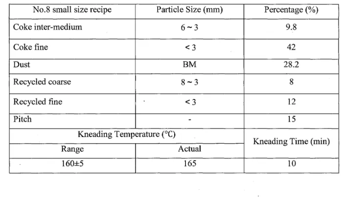
Table 5.8 The formulation conditions for No.8 small particle size recipe
No.8 small size recipe Coke inter-medium Coke fine Dust Recycled coarse Recycled fine Pitch Particle Size (mm) 6-3 <3 BM 8-3 < 3 -Kneading Temperature (°C) Range 160±5 Actual 165 Percentage (%) 9.8 42 28.2 8 12 15
Kneading Time (min) 10
Table 5.9 presents the measured properties of the anodes prepared using the above recipes. From this table, it can be clearly seen that No.4 recipe in which the maximum particle size was 8 mm had better properties than the anodes made with the other recipes. The air reactivity residue was higher than those of all the others with the exception of recipe 5. The recipe 5 anodes had slightly higher residue for air reactivity; however, its CO2 reactivity residue was much lower compared to that of the No.4 recipe anode showing higher CO2 reactivity. Also, No.4 recipe anode had the lowest permeability among others. Thus, the No.4 recipe was chosen to improve the properties further by optimizing the recycled butt content.