HAL Id: hal-02489033
https://hal.archives-ouvertes.fr/hal-02489033
Submitted on 24 Feb 2020
HAL is a multi-disciplinary open access
archive for the deposit and dissemination of
sci-entific research documents, whether they are
pub-lished or not. The documents may come from
teaching and research institutions in France or
abroad, or from public or private research centers.
L’archive ouverte pluridisciplinaire HAL, est
destinée au dépôt et à la diffusion de documents
scientifiques de niveau recherche, publiés ou non,
émanant des établissements d’enseignement et de
recherche français ou étrangers, des laboratoires
publics ou privés.
Coded OFDM and OFDM/OQAM for intensity
modulated optical wireless systems
Mamdouh El Tabach, Patrick Tortelier, Ramesh Pyndiah, Olivier Bouchet
To cite this version:
Mamdouh El Tabach, Patrick Tortelier, Ramesh Pyndiah, Olivier Bouchet.
Coded OFDM and
OFDM/OQAM for intensity modulated optical wireless systems. JOCM Journal des Communications,
Engineering and Technology Publishing (ETP), 2009, 4 (8), pp.555 - 564. �10.4304/jcm.4.8.555-564�.
�hal-02489033�
Coded OFDM and OFDM/OQAM for Intensity
Modulated Optical Wireless Systems
Mamdouh El Tabach
1, Patrick Tortelier
1, Ramesh Pyndiah
2and Olivier Bouchet
11
France Télécom, Orange Labs, 4 rue du Clos Courtel, 35512 Cesson-Sévigné Cedex, France Email: {Mamdouh.Eltabach, Patrick.Tortelier, Olivier.Bouchet}@orange-ftgroup.com
2 IT-TELECOM Bretagne, SC Department, Technopôle Brest-Iroise, CS 83818, 29238 Brest Cedex 3, France
Email: [email protected]
Abstract— Infrared optical wireless (OW) is a promising
technology associating free-space propagation and infrared radiation for home networks. OW offers several advantages over radio technologies, making it an attractive solution for short range communications. However, OW technology is not as mature as for radio; further advanced studies regarding optical components and physical layer issues are still open. Coded orthogonal modulations such as Coded OFDM (COFDM) are currently used in many radio and fixed transmission systems. Among these modulations, COFDM/OQAM is an interesting alternative to classical COFDM modulation, as it does not require the use of a guard interval and it has an optimal spectral efficiency. In this paper, we present a comparative study of modified COFDM and modified COFDM/OQAM schemes adapted to intensity modulation and direct detection over a diffuse channel based on experimental measurements. If M-ary QAM modulation is used, the two schemes offer the possibility to increase the bit rate of OW communications. They also mitigate the effects of inter symbol interference (ISI). On the other hand, modified COFDM/OQAM could outperform modified COFDM schemes with a cyclic-prefix.
Index Terms— OW, optical wireless, infrared, FSO, intensity modulation, IM/DD, COFDM, OQAM
I. INTRODUCTION
Infrared optical wireless (OW) benefits from a number of advantages qualifying it as an alternative, or a serious complementary solution to radio frequency transmission [1, 2]. First, OW takes advantage of the unregulated and unlicensed optical spectrum. Also, we do not have any kind of interference with existing radio systems. Since optical waves are stopped by walls, transmission security is ensured and frequency reuse is much easier. Under good conditions, OW should support high bit rates needed for multi-media services. However, besides these advantages, and in a diffuse propagation, the channel suffers from frequency selectivity causing inter symbol interference (ISI) problems and decreasing the achievable data rate.
Orthogonal frequency division multiplexing (OFDM) converts a frequency-selective channel into a set of parallel frequency-flat fading channels. This is, of course, only valid if the cyclic-prefix (CP) is longer than the maximum delay spread introduced by the channel. In
addition, the OFDM efficiency is only optimal when a channel coding is associated to it [3]; we are talking about coded OFDM (COFDM). This makes cyclic-prefix COFDM a suitable scheme to be associated with wireless applications like OW [4]. Nevertheless, there exist other COFDM based modulations such as coded OFDM/offset QAM (COFDM/OQAM) [5-8] for which no cyclic-prefix is required. These modulations are robust to both frequency and time selectivity. In this paper, we compare these two schemes in the OW context. In Section II, we briefly describe the OW technology. In Section III, we present generalities about OFDM/OQAM modulation. In Section IV, we provide the common architecture for studied schemes before recalling the required adaptation of COFDM and COFDM/OQAM to OW characteristics. In Section V, we provide system performance over corresponding infrared channels. Finally, in Section VI, we give conclusions and perspectives.
II. OPTICAL WIRELESS TECHNOLOGY
First, we describe OW propagation models; we focus on the equivalent baseband model, which is different from classical baseband models in radio-frequency systems. We also give noise and diffuse channel characteristics.
A. Propagation Models
There are several OW topologies of propagation in limited indoor space [9]. Line of sight (LOS) propagation is the simplest typology in optical wireless systems and the most commonly used in point-to-point systems. In this configuration, the transmitter and the receiver must be oriented towards each other to establish a permanent or temporary link by removing any obstacles between them. The majority of the transmitted beam is then directed towards the receiver.
Wide line of sight (WLOS) typologies are characterized by transmitters with wider divergence angles and receivers having larger field of view (FOV) than those of LOS typology. This wide coverage area offers a greater freedom with respect to the alignment between transmitters and receivers; however it can significantly decrease the received optical power.
In a diffuse (DIF) typology, independently of the obstructing objects, the link is always maintained
between the transmitter and the receiver. This is thanks to multiple reflections of the optical beam on surrounding surfaces such as ceilings, walls and furniture. In this case, the transmitter and the receiver are not necessarily directed towards one another; the transmitter benefits from an important beam divergence and the receiver has a very large FOV. This corresponds to the general case of OW multipath channel [10].
B. Baseband Model
The phase control of an optical signal is rather difficult and expensive to achieve. Moreover, in the case of one or several reflections, we obtain a potential modification of the phase. Because of difficulties in detecting the phase in wireless optics, the majority of the current systems use intensity modulations (IM) techniques, such as on/off keying (OOK), and pulse position modulation (PPM) [11]. The information is coded by the instantaneous optical power of the emitting diode. On the other hand, the reception is a direct detection (DD), in which the photodetector produces a photocurrent proportional to the received optical power. More precisely, it is proportional to the integral on the photodetector surface of the instantaneous optical power received in each point of the detector. This type of transmission is commonly called IM/DD [12].
Multiple reflections lead to spatial variations of magnitude and phases of the optical received signal. In mobile radio channels, multipath fading is generally experienced as the detector is smaller than a wavelength. However, in OW communications, multipath fading is not present due to the very high ratio between photodetector area and optical wavelength. The output of the photodetector is thus, a spatial mean of the instantaneous received signal over the photodiode area vanishing fading values. But, in the time domain, as the transmitted optical power propagates along various paths of different length, OW communications suffer from multipath distortion. ISI problems become seriously harmful in diffuse mobile configurations. The baseband channel can be modeled as [9]
) ( ) ( ) ( ) (t R xt ht n t y = ⊗ + (1)
where
⊗
denotes the convolution operator, x(t) the transmitted optical power, y(t) the received photocurrent,R the photodiode responsivity, h(t) the channel impulse
response (CIR) and n(t) the different noise contributions. This baseband model differs from radio models. The channel input in this equivalent baseband model is an optical power, x(t) is non-negative
0 ) (t ≥
x (2)
Thus, the time average transmitted signal is positive and should be seen as the average transmitted optical power Pt
∫
+ − ∞ → = T T T t x t dt T P () 2 1 lim (3)Thus Pt is proportional to a time integral of x(t) rather than the usual x2, which is appropriate in radio communications when x(t) represents amplitude.
Another important parameter is the channel gain H(0) at the null frequency, which is given by
∫
+∞ ∞ − = ht dt H(0) () (4)Received optical power is a crucial parameter in any optical system evaluation. When its value is lower than the receiver sensitivity, the system does not work any more. The average received optical power can be written in the form of
(
)
( )
t T T T r x t h t dt H P T P () () 0 2 1 lim = ⊗ =∫
+ − ∞ → (5) C. Noise NatureDepending on the environment, the noise spectral distribution is an important factor in determining the suitable wavelength and analyzing system performance. In OW links, the noise n(t) can be split into three main components:
• thermal noise due to thermal effects in the receiver, • periodic electric noise resulting from the variation of
fluorescent lamps or tubes due to the method used for driving the lamp using the ballast,
• and shot noise, which is the dominant one in a well-designed indoor receiver
B NSS shot t 0 x 2 2 ≅σ = σ (6) where NSS
0 is the single-sided power spectral density, and
B the modulation bandwidth. From a theoretical point of
view, shot noise depends on the entire incident light, useful and background, striking the detector. However, received background power is very high with respect to signal useful power, even if the receiver uses an appropriate optical filtering. Hence, we can neglect the shot noise caused by the signal and model the ambient-induced shot noise as Gaussian
(
inc d)
(
u bg d)
bg SSqI
I
I
I
q
I
I
q
N
0=
2
+
=
2
+
+
≅
2
(7)where q is the electron charge, Iinc is the photocurrent due to all incident power, Id is the obscurity dark current, Iu is the useful photocurrent and Ibg is the background photocurrent proportional to the ambient light background power:Ibg =R Pbg.
When we have only a single direct path without reflection, this LOS/WLOS channel is similar to the well- known additive white Gaussian noise (AWGN) channel.
5 10 15 20 0 0.05 0.1 0.15 0.2 0.25 0.3 0.35 Time in ns h (t ), n o rm a lz e d u n it
Gfeller & Bapst channel
(a) 0 10 20 30 40 50 60 70 80 90 0 0.1 0.2 0.3 0.4 0.5 0.6 Time in ns h (t ), n o rm a liz e d u n it Techim@ges channel (b)
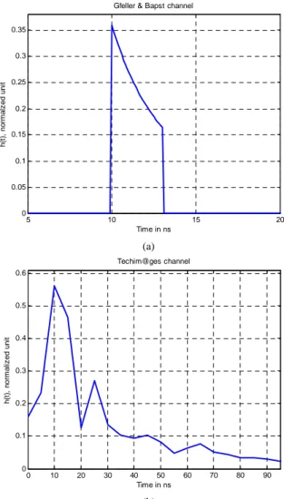
Figure 1. Diffuse Channel impulse response with FOV=40° and d=3m.
D. Diffuse Channel Impulse Response
First, we recall the first theoretical multipath DIF channel detailed in the pioneering article of Gfeller and Bapst [13]. It assumes only one optical reflection. However, this reflection can yield multiple discrete channel coefficients in the baseband model depending on the bit rate. An optical source illuminates a ceiling or a plane surface. At timet=0, the beam is reflected towards the photodiode. At the propagation delay t, the CIR is modelled as
( )
(
)
≤ ≤ = otherwise , 0 ) cos( , sin 2 0 0 3 2 0 FOV t t t t FOV t t h (8)The term t0 is the minimum delay equal to d/c where d is the distance between a reflecting plane surface and the receiver and c is the speed of light. Fig.1 a) shows h(t) for
m
d=3 and a FOV of 40°. It seems that the channel width is less than 4 nanoseconds. This model is important as a reference model; however, as we will see later, in some concrete cases, the exact CIR may be different.
Other different tools have been proposed in order to estimate the impulse response in real conditions [10, 14,
and 15]. Some of them are only simulation programs, while others are experimental methods developed to measure the influence of real indoor environments on the CIR. The major limitation of such methods is due to the optical link margin. In DIF typologies, a reliable impulse response would require a huge transmitted optical power. Without using walls with high reflectivity, authors from the Techim@ges project propose characterizing the CIR of a real room by measuring the impulse response on a reduced size model [14].
In this paper, we present results obtained by the same method detailed in [14]. The goal of the measurements taken by colleagues at ENSSAT (Lannion) is to investigate optical wireless multipath effects in DIF environments with no direct path. We choose the spectral analysis method directly giving the channel frequency response H (f); the CIR h(t) is easily found using the inverse discrete Fourier transform (IDFT). We employ a network analyzer, a 1550-nm laser diode transmitting continuously, a light shaping diffuser yielding to 60° of divergence, and a photodiode associated to an optical concentrator having a FOV of 40°. The channel is composed of an empty 50cm x 50cm x 30cm reduced room model, covered with white papers. The distance between transmitter and receiver is 30 cm. For a 5m x 5m x 3m real room, a time scaling factor of 10 and an amplitude correction factor of 1 10could be used [14].
Fig.1 b) shows h(t) experimental results based on this assumption. In the absence of a LOS path and the presence of multiple reflections, we notice a relatively huge power loss and a remarkable channel up to maximum of 90 ns. This channel will be named Techim@ges channel.
III. OFDM/OQAMMODULATION
In the following we describe generalities on OFDM/OQAM which is an alternative to classical OFDM.
A. OFDM/OQAM Transmitter
Contrary to classical OFDM with a cyclic-prefix, OFDM/OQAM modulation does not require the use of a guard interval, which leads to a gain in spectral efficiency. A similar performance can be achieved by modulating each sub-carrier by an optimized prototype function. To obtain a sufficient robustness to the channel variations, this prototype function must be very well localized in both time and frequency domains.
The orthogonality between the sub-carriers must also be maintained after the modulation. Near optimally localized functions having these properties exist, but they only guarantee orthogonality on real values. An OFDM modulation using these features is denoted OFDM/OQAM. We note that in OFDM/OQAM, each sub-carrier carries a real-valued symbol am,n which corresponds to either the real part or the imaginary part of a complex OFDM symbol cm,n, where m is the frequency index, and n is the time index. OFDM/OQAM has the same spectral efficiency as the classical OFDM with no guard intervals. This means that the density of the
sub-carriers in the time-frequency plane is twice greater in OFDM/OQAM than in classical OFDM, with a zero-length cyclic prefix.
The elementary signal corresponding to the nth OFDM/OQAM symbol is given by
( ) 0 0 1 0 t 0 2 , ) 1 ( with ) ( ) ( , τ τ τ π n t n n t f e i a t s Q m f Ft m i n m n m n n m ≤ ≤ − − =
∑
− = ∆ + (9)where Q is the number of sub-carriers, am,n is the real-valued symbol transmitted on the mth sub-carrier at the nth symbol; f(t) denotes the real-valued prototype function, and fm,n(t) its shifted versions in time and frequency. The overall OFDM/OQAM transmitted signal can be expressed as follows
( )
( )∑ ∑
∑
+∞ −∞ = − = ∆ + +∞ −∞ = − = = n Q m f Ft m i n m n m n n n m n t f e i a t s t s 1 0 t 0 2 , , ) ( ) ( π τ (10)The orthogonality condition between the sub-carriers is real; it is given by
( )
( )
(
0 0)
, 0 ,0 * , , Re∫
fmn t fm n tdt =δmmδnn (11) B. OFDM/OQAM ReceiverIn a distortion and noise free channel, the demodulated symbol over the mth sub-carrier at the nth instant is
( ) ( )
( ) ( ) ce interferen intrinsic : * , ' ,' , ' ,' ' ,' , * , , ,n m I n m n m n m n m n m n m n m n m stf tdt a a f f dt r (∫
∑
∫
≠ + = = (12)According to (11), the right part of (12) is a pure imaginary form. Thus, by simply considering the real part of rm,n we can perfectly recover the transmitted symbol.
After passing through the channel, adding noise contribution n(t) and before demodulation, the received signal can be expressed as
) ( ) ( ) ( , 1 0 , , a f t n t h t z mn n Q m n m n m + =
∑ ∑
+∞ −∞ = − = (13)As the OFDM/OQAM prototype function f(t) is chosen to be well localized both in time and frequency domains, the intrinsic interference term only depends on a restricted set of time-frequency positions (m',n') around the considered symbol. Assuming that hm,n is constant over the summation zone, we can demodulate by
( ) ( )
t f tdt z rmn mn * , , =∫
( ) ( ) mn I n m n m n m n m n m n m n m n m h a a f f dt n r n m , ce interferen intrinsic : * , ' ,' , ' ,' ' ,' , , , , + + =∑
∫
≠ ( (14)With a good approximation, after equalization, a simple threshold applied on the real part of the demodulated symbol in (14) should be sufficient.
In practice, to generate an OFDM/OQAM signal, we use discrete domain transform. Equation (10) becomes:
[ ]
[ ]
− = = − − + ∞ + −∞ = − = +∞ −∞ =∑∑
∑
2 2 1 2 1 0 , Q n k f e i a k s k s p L k Q m i n m n Q m n m n n π (15)where k is the discrete time coefficient and Lp is the prototype filter length. Previous description is still valid and equations (11) to (14) are easily converted to discrete representation.
A particular prototype function called IOTA (Isotropic Orthogonal Transform Algorithm) satisfying (11) is considered in this paper. To simplify the notations, in the following we call OFDM/IOTA an OFDM/OQAM system using the IOTA function. With IOTA prototype function, it is possible to assume as in [7] that the intrinsic interference I(m,n depends on the 8 nearest
neighbors of am,n.
IV. SYSTEM ARCHITECURE
We consider the general architecture of the two tested techniques: modified COFDM and COFDM/OQAM schemes designed under OW constraints.
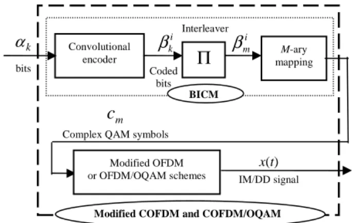
A. Common Transmitter Architecture
We consider in the following, the bit-interleaved coded modulation (BICM) scheme shown in Fig.2. Frames of (N-2) information bits αk are encoded by a rate Rc =12 convolutional encoder with memory 2 and octal generator polynomials (1,5/7); 2 tail bits are appended at the end of each frame to ensure zero-state trellis termination. The 2N coded bits i
k
β with k = 0,1,...,N-1 and i = 1,2 are interleaved according to a pseudo-random permutation function, grouped and mapped onto 2N log2M
discrete-time M-ary QAM complex symbols cm =am+ jbm at the symbol rate Rs = 1/T symbol per second with:
• mean mc=E
{ }
cn , • variance 2{
{ }
2}
n n c =E c −Ec σ ,• and electrical power:
{ }
* = n c c E n E{ }
cn2 2 2 c c+m =σWe assume that the symbols are independent and identically distributed (i.i.d). Note that in radio-frequency systems the zero-mean is often true and the electrical power and variance of the symbols are thus, the same
σ
c2=E{ }
cn2 .Complex symbols cm are then processed by either the modified OFDM or OFDM/OQAM schemes. The resulting signal x(t) represents an optical intensity as specified previously and it should be non-negative.
Figure 2. General transmitter architecture.
This requires adaptation schemes described in Sections IV.C and IV.D. The BICM and the modified OFDM or OFDM/OQAM blocks are denoted modified COFDM and COFDM/OQAM transmitters, respectively.
B. Common Receiver Architecture
We use the same sampling frequency Rs for both systems, whereas the bit rate is slightly higher for the modified COFDM/OQAM scheme. The cascade of the transmit filter, the transmission channel, the receive filter and the symbol-rate sampling may be represented by an equivalent discrete-time baseband channel, modeled as a finite impulse response (FIR) filter with Lc real coefficients h[k]. After passing through the channel, the light wave is converted into a photocurrent. The signal at the photodiode output is corrupted by additive, zero-mean, symmetric white Gaussien noise n[k] with a total variance 2
n
σ . The electric receiver observes the noisy channel output y[k] given as
[ ]
k R h[ ] [ ] [ ]
ixk i nk y c L i + − =∑
− = 1 0 (16)The receiver consists of a cascade of the following functions: OFDM or OFDM/OQAM demodulation, M-ary QAM demapping, deinterleaving and hard input convolutional decoder. Note that system performance can be improved using soft input convolutional decoder [16].
C. Modified OFDM Scheme
As we have shown, OW transmitted baseband signal must be real and positive. But in conventional OFDM and in OFDM/OQAM, the transmitter output is complex. Two main adaptations are required: the applications of Hermitian symmetric conditions and an offset bias. • Hermitian symmetric conditions
The continuous-time signal corresponding to the nth OFDM symbol is given by
0 0 1 0 0 2 , ) 1 ( ) ( ) ( nT t T n nT t p e c t s Q m Ft m i n m n ≤ ≤ − − =
∑
− = ∆ π (17)where cm,n are the complex digital symbols cm at the nth time index, Q is the sub-carrier number, ∆F is the inter-carrier spacing, T0 = 1/∆F the duration of the OFDM symbol and p(t) is the rectangular prototype function of duration T0.
For an arbitrary time t, the total transmitted OFDM signal is
( )
( ) ) ( 0 2 1 0 , e p t nT c t s t s im Ft n Q m n m n n = − = +∞ ∆ −∞ = − = +∞ −∞ =∑ ∑
∑
π (18)When sampling at T=1/Rs =T0/Q, (18) is equivalent to the inverse discrete Fourier transform (IDFT)
[ ]
k s[ ]
k c e p[
k nQ]
s k Q m i n Q m n m n n = − =∑
∑ ∑
+∞ −∞ = − = +∞ −∞ = π 2 1 0 , (19)[ ]
ksn is the discrete signal corresponding to sn
( )
t . LetP=Q/2, (19) becomes
[ ]
[
]
( )
+ + − + − =∑
∑
− = − − +∞ −∞ = 1 1 2 2 , 2 2 , , , 0 1 P m k P m Q i n m Q k P m i n m k n P n n e c e c c c nQ k p k s π π (20)Given that p[k] is real, so
∀
k
, s[k] is real if = = − ,otherwise , 0 if , 0 * , , n m Q n m c P m c (21)Therefore, if the discrete input sequence of the OFDM modulator has its first and center coefficients null and if it presents Hermitian symmetry with respect to its center, then the OFDM time modulated signal is real.
• Positivity constraint
To ensure that the transmitted signal is positive, an offset is required. The DC value must be chosen carefully in parallel to a clipping technique. In our equivalent baseband model, the discrete channel input, which is real and positive, becomes
DC k s k
x[ ]= [ ]+ (22)
In order to save power while ensuring positivity, DC must be as small as possible. As the symbols cm,n are centered around zero, the average of s[k] is null; DC is equal to the transmitted optical power Pt.
Here, we use an adjustable DC depending on each OFDM symbol. For k = 0…Q-1, each real positive OFDM symbol will be of the form
[ ] [ ]
n n n DC k s k x = + (23) Convolutional encoder k α i kβ
Coded bits bitsΠ
i mβ
M-ary mapping Interleaver BICM Modified OFDM or OFDM/OQAM schemes x(t) IM/DD signalModified COFDM and COFDM/OQAM
m
c
[ ]
( )
s k DC n Q k n 1 0 min − ≤ ≤ − = (24)In this case, the transmitted optical power Pt will be equal to the average of allDCn
[ ]
nt EDC
P = (25)
where E[.] is the mathematical expectation.
If, for system design requirements, normalizing Pt to a fixed value is imposed, we can simply adapt optical level by a multiplication factor.
Light wave is converted into photocurrent. According to (16) and (24), the photodiode discrete output corresponding to the nth symbol is
( )
0 [ ] ] [ ] [ ] [k R s k hk R H DC nk yn = n ⊗ + n+ (26)Then, the offset contribution can be removed by subtracting RH(0)DCn. The input of OFDM demodulator will be
[ ]
∑
+∞[
]
∑
−∞ = − = + − = n P m n m k P m i n m e h nk c nQ k p R k y' 2 Re [ ] 1 1 , 2 2 , π (27)and after that, the OFDM demodulation is performed. Although it may be done systematically in optical applications, we should note that it is not required to subtract the offset component. It only affects the first point of the DFT block at the zero frequency.
As stated in the introduction, to combat delay spreads over multipath channels, a CP should be added at transmission and removed at reception before demodulation. The CP duration ∆ must be greater than the maximum delay spread.
Once the CP is removed and DFT is performed, for each frequency packet, only the first (P-1) samples after the zero frequency,
{ }
cˆk,n 1≤k≤P−1, are considered and passed to the following module. The estimated frequency sample is given byn m n m m n m g c w cˆ , = , + , (28)
where gm =RHm2 denotes the gain of the DFT transform. Hk is the Q-DFT of the channel impulse response with
∑
− = − = 1 0 2 exp Q m m k Q mk j h H π (29) ≤ ≤ = otherwise 0 1 -0 if c m m L m h hThe sample is corrupted by an additive, zero-mean, symmetric white Gaussian noise wm,n with mean varianceσw2 = h 2σn2 with
2
h representing the channel
energy. From (7) and (28), we can define the signal to noise ratio at the DFT output as
s bg c out R qRP h R SNR 2 2 2 σ = (30)
D. Modified OFDM/OQAM Scheme
As for the modified OFDM scheme, two adaptations are required to guarantee that the modulator has a real-valued positive output.
• Hermitian symmetric conditions
From Section IV.C, to guarantee the constraint of real-valued OFDM modulated signal, the discrete input sequence of the modulator should present Hermitian symmetry with respect to its center and should have its center and first coefficients null. Being an OFDM based modulation, OFDM/OQAM inherits from many properties related to classical OFDM systems. For instance, Hermitian symmetry conditions could be rewritten. The design of OFDM/OQAM modulation with Hermitian symmetry was introduced by Lin and Siohan in [8].
The expression of the OFDM/OQAM transmitted signal can be written from (15) by
[ ]
k a i e f[
k nP]
s D k P m i n m n Q m n m − = − + ∞ + −∞ = − =∑ ∑
2 2 2 1 0 , π (31)where D=Lp-1 and P=Q/2 is the half number sub-carriers.
Let us factor out the first and Pth frequency coefficients
[ ]
[
]
+ + + − =∑
∑
∑
− + = − + − = − + − + ∞ + −∞ = 1 1 2 2 2 , 1 1 2 2 2 , 2 , , 0 Q P m D k P m i n m n m P m D k P m i n m n m D k i n P n P n n n e i a e i a e i a i a nP k f k s π π π (32) which is equivalent to[ ]
[
]
+ + + − =∑
∑
− = − − + − − − + − + ∞ + −∞ = 1 1 2 2 2 , 2 2 2 , 2 , , 0 P m D k P m Q i n m Q n m Q D k P m i n m n m D k i n P n P n n n e i a e i a e i a i a nP k f k s π π π (33)In OFDM/OQAM, the most used prototype functions like IOTA have real coefficients, and thus f [k] is real.
Therefore,∀k s[k] is real if • + − + 2 , , 0 D k i n P n P n ni a i e a π is real and • * 2 2 2 , 2 2 2 , = − − + − − − + D k P m Q i n m Q n m Q D k P m i n m n m i e a i e a π π
As am,n are real-valued symbols, the solution is
( )
− = = − − − 1 ,otherwise , 0 if , 0 , , D P n n m Q P n m a m a (34)Following these conditions, the output of the modified OFDM/OQAM is real
[ ]
∑
+∞[
]
∑
−∞ = − = − + − = n P m D k P m i n m n m i e a nP k f k s 1 1 2 2 2 , Re 2 π (35) • Positivity constraintAs for the modified OFDM scheme, modified OFDM/OQAM scheme needs positivity constraint too. In the same manner as described in Section IV.C, we propose to add an adjustable DC level, so that Pt and DC are normalized. In the reception, the DC contribution can be similarly removed. Equations (26), (27) and (35) give
[ ]
k f[
k nP]
a i e h n[ ]
k y n P m n m D k P m i n m n m + − =∑
+∞∑
−∞ = − = − + 1 1 , 2 2 2 , Re 2 ' πAnd then, OFDM/OQAM demodulation is performed exactly as described in Section III.B. We note that, as for OFDM, the DC bias affects the first un-used frequency. At the output of the OFDM/OQAM demodulator, the frequencies of interest are characterized by the same
SNRout, as in OFDM, given in (30).
V. SIMULATION AND PERFORMANCE
In the following, we give simulation parameters and the bit error rates (BER) curves of modified COFDM and COFDM/OQAM over OW channels.
A. Simulation Parameters
In all simulations, we give BER performance versus
SNRout calculated after COFDM or COFDM/OQAM demodulation, as indicated in (30). More precisely, we adopt the parameter useful SNRu defined as
out u LSNR
SNR = (36)
where L is the possible loss factor due to the implementation of a guard interval:
0 0 T T LCP ∆ +
= , in the case of COFDM
LOQAM=LOOK=1, for COFDM/OQAM and OOK.
The period T0 is the useful OFDM symbol duration and ∆ is the cyclic-prefix duration. We note that some single carrier systems may need a guard interval too. On the other hand, due to its inherent properties, COFDM/OQAM does not require this guard interval. We define the spectral efficiency by η=Rclog2M BT,
which tells us how many bits per second and per Hertz are transmitted considering the bandwidth B. Let us compare the optical IM/DD modified COFDM, modified COFDM/OQAM systems with M-QAM modulation to classical BICM single carrier transmission with OOK minimum bandwidth modulation. At the same sampling frequency, we obtain
η OOK/SC= RcLOOK bit/s/Hz
η COFDM = Rclog2M [(P-2)/2P]LCP bit/s/Hz (37)
ηCOFDM/OQAM= Rclog2M [(P-2)/2P]LOQAM bit/s/Hz
The spectral efficiency of OOK is approximately identical to that of COFDM/OQAM and COFDM without a guard interval for 4-QAM. However, increasing the order of the modulation will increase the useful data rate in favor of modified COFDM/OQAM and COFDM.
B. Bit Error Rate Analysis
To prove the concept, we first compare the two basic schemes over a LOS/WLOS channel having one single path. Fig. 3 captures performance for 4-QAM modulation. As the channel is strictly constant over the whole time-frequency plan, the guard interval is omitted and the performance of COFDM without CP and COFDM/OQAM are identical. We see that even the performance gain, due to channel coding, is the same in the two cases. Compared to single carrier systems, at the same sampling frequency, 4-QAM associated to modified COFDM or COFDM/OQAM has practically the same bit rate as binary OOK modulation.
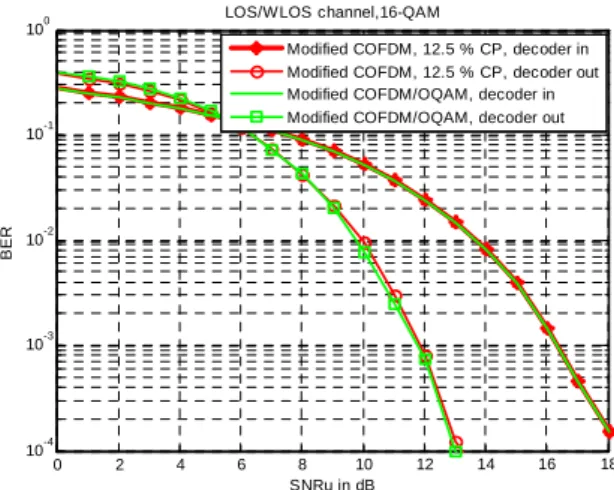
Let us increase the order of modulation. Using 16-QAM, the bit rate and the spectral efficiency of COFDM without CP and COFDM/OQAM are double. Fig. 4 shows that, in the case of a LOS/WLOS channel, modified COFDM without CP and COFDM/OQAM are always identical in terms of BER analysis at the input and the output of the channel decoder. For 4-QAM and 16-QAM, the used channel coding enhances COFDM performance as much as COFDM/OQAM. At a BER of 10-3, this gain is always about 4 dB.
Then, we study the performance over the Gfeller & Bapst theoretical channel. The discrete-time CIR is characterized by four coefficients (Lc=4) and it is given in the following equations at sample rate Rs = 1 GHz:
[
0.359;0.2698;0.2078;0.1634]
= k
h
The total number of sub-frequencies, i.e. DFT size in COFDM, is equal to 32 and the cyclic-prefix size is fixed to 4. Fig. 5 shows performance for 4-QAM modulation. Modified COFDM/OQAM outperforms modified COFDM by 0.5 dB. This gain is due to the elimination of the cyclic-prefix while ensuring a quasi-optimal localization in time-frequency plan. Over this dispersive channel, the channel coding gain is greater than in LOS/WLOS channel. At a BER of 10-3, the gain achieved is 6 dB. Over the same channel and passing to 16-QAM, Fig. 6 proves that the gain in favor of COFDM/OQAM is always present.
0 1 2 3 4 5 6 7 8 9 10 11 10-4 10-3 10-2 10-1 100
LOS/WLOS channel, 4-QAM
SNRu in dB
B
E
R
Modified COFDM, zero CP, decoder in Modified COFDM, zero CP, decoder out Modified COFDM/OQAM, decoder in Modified COFDM/OQAM, decoder out
0 2 4 6 8 10 12 14 16 18 10-4 10-3 10-2 10-1 100
LOS/W LOS channel,16-QAM
SNRu in dB
B
E
R
Modified COFDM, 12.5 % CP, decoder in Modified COFDM, 12.5 % CP, decoder out Modified COFDM/OQAM, decoder in Modified COFDM/OQAM, decoder out
Figure 3. 4-QAM modified schemes over LOS/WLOS channel. Figure 4. 16-QAM modified schemes over LOS/WLOS channel.
0 2 4 6 8 10 12 14 16 18 10-4 10-3 10-2 10-1 100
Gfeller & Bapst channel, 4-QAM
SNRu in dB
B
E
R
Modified COFDM, 12.5 % CP, decoder in Modified COFDM, 12.5 % CP, decoder out Modified COFDM/OQAM, decoder in Modified COFDM/OQAM, decoder out
4 6 8 10 12 14 16 18 20 22 24 26 10-4 10-3 10-2 10-1 100
Gfeller and Bapst channel, 16-QAM
SNRu in dB
B
E
R
Modified COFDM, 12.5 % CP, decoder in Modified COFDM, 12.5 % CP, decoder out Modified COFDM/OQAM, decoder in Modified COFDM/OQAM, decoder out
Figure 5. 4-QAM modified schemes over Gfeller & Bapst channel. Figure 6. 16-QAM modified schemes over Gfeller & Bapst channel.
0 2 4 6 8 10 12 14 10-4 10-3 10-2 10-1 100
Techim@ges channel, 4-QAM
SNRu in dB
B
E
R
Modified COFDM, 12.5 % CP, decoder in Modified COFDM, 25 % CP, decoder in Modified COFDM, 50 % CP, decoder in Modified COFDM/OQAM, decoder in
0 2 4 6 8 10 12 14 10-4 10-3 10-2 10-1 100 Techim@ges channel,4-QAM SNRu in dB B E R
Modified COFDM, 50 % CP, decoder in Modified COFDM, 50 % CP, decoder out Modified COFDM/OQAM, decoder in Modified COFDM/OQAM, decoder out
Figure 7. Input decoder of 4-QAM different modified schemes. Figure 8. 4-QAM modified schemes over Techim@ges channel.
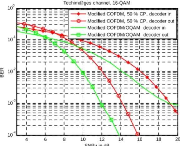
Now, we simulate these two adapted systems over the experimental Techim@ges channel, corresponding to an empty room, with a sampling frequency Rs= 150
MHz.
The number of coefficients is Lc= 14
= 0708 . 0 ; 0328 . 0 ; 0347 . 0 ; 0217 . 0 ; 0789 . 0 ; 0639 . 0 ; 0531 . 0 ; 0240 . 0 ; 012 . 0 ; 0056 . 0 ; 0063 . 0 ; 0021 . 0 ; 0329 . 0 ; 5613 . 0 k h
Although the first path contains relatively a very good concentration of the power, the high number of other interference coefficients may be harmful and needs an adapted design. We fix the number of sub-carriers to 32 and test three cases with ∆ equal to 4, 8 and 16 for modified COFDM.
Associated to 4-QAM, Fig. 7 shows their respective performance when compared to COFDM/OQAM. At a BER of 10-2 calculated at the channel decoder input, COFDM/OQAM has at least 2 dB of gain. However,
4 6 8 10 12 14 16 18 20 10-4 10-3 10-2 10-1 100
Techim@ges channel, 16-QAM
SNRu in dB
B
E
R
Modified COFDM, 50 % CP, decoder in Modified COFDM, 50 % CP, decoder out Modified COFDM/OQAM, decoder in Modified COFDM/OQAM, decoder out
Figure 9. 16-QAM modified schemes over Techim@ges channel.
for smaller BER at the decoder input, we can see that this gain tends to zero; below a BER of 8.10-4, the modified COFDM gives better performance. This also corresponds to results without channel coding over the same dispersive channel. Let us study the effect of the channel decoding. Fig. 8 captures the BER curves calculated at the channel decoder output. With channel coding, the modified COFDM/OQAM manages to avoid losses for lower BERs; it preserves its advantage over modified COFDM for all BERs by about 2 dB.
Fig. 9 illustrates the case of 16-QAM modulation over the Techim@ges channel. Similar conclusions may be drawn: the modified COFDM/QOAM always outperforms the modified COFDM by nearly 2 dB at the decoder output; this gain only appears at high BERs at the decoder input. This last inconvenience is transparent to the user as we believe that practical systems will use a channel coding.
VI. PERSPECTIVES AND CONCLUSION
In this paper, we considered two multi-carrier schemes adapted to intensity modulation and direct detection: the modified COFDM and COFDM/OQAM techniques. A performance analysis is done for complete transmission chains with channel coding over different kinds of channels. These two schemes can easily be associated to complex multi-level QAM modulations. Compared to binary modulations, they have the potential to increase the bit rate. Whilst mitigating frequency selectivity and ISI effects, COFDM/OQAM benefits from optimal spectral efficiency. We show that over a real room channel based on measurements, the modified COFDM/OQAM scheme could perform well, when the modified COFDM requires a cyclic-prefix and implies a loss in spectral efficiency. The Modified COFDM/OQAM leads to significant gains over such kind of channels. Based on these promising preliminary results, further studies building an experimental end-to-end demonstrator, would provide a more complete picture of the performance of modified COFDM/OQAM and modified COFDM for infrared OW systems.
ACKNOWLEDGMENT
The authors would like to thank Professor Pascal Besnard and his team from FOTON/ENSSAT-Lannion (France) for their helpful contribution in establishing optical measurements. They would also like to thank their colleagues: Dominique Leroux from TELECOM Bretagne and Rodolphe Legouable from Orange Labs for fruitful discussions and suggestions.
REFERENCES
[1] Z. Ghassemlooy and A R Hayes, “Indoor optical wireless communications systems – Part I: Review,”
School of Engineering, Northumbria University, UK,
2003.
[2] O. Bouchet, M. El Tabach, D. Leroux, P. Besnard and
M. Bertrand, “Personal optical wireless
communications: a generic LOS/WLOS propagation model,” WWRF 19, Chennai, India, November 2007. [3] B. Le Floch, M. Alard and C. Berrou, “Coded
orthogonal frequency division multiplex,”, IEEE
Proceedings, 1995, vol. 83, n°6, pp. 982-996.
[4] Y. Tanaka, T. Komine, S. Haruyama and M. Nakagawa, “A basic study of optical OFDM system for indoor visible communication utilizing plural white LEDs as lightening,” ISMOT 2001, Montreal, Canada, pp.303-306.
[5] P. Siohan, C. Siclet, and N. Lacaille, “Analysis and design of OFDM/OQAM systems based on filterbank theory,” IEEE Transactions on Signal Processing, May 2002, vol. 50, n°5, pp. 1170-1183.
[6] H. Bölcskei, “Orthogonal frequency division
multiplexing based on offset QAM,” in Advances in
Gabor Analysis, Birkhäuser, Boston, 2003, pp. 321–352.
[7] M. El Tabach, J. P. Javaudin and M. Hélard, “Spatial data multiplexing over OFDM/OQAM modulations,”
IEEE Proceedings, ICC, Glasgow, Scotland, June 2007,
pp. 4201-4206.
[8] H. Lin, and P. Siohan, “OFDM/OQAM with Hermitian symmetry: design and performance for baseband communication,” IEEE Proceedings, ICC, Beijing, China, May 2008, pp. 652-656.
[9] J.M. Kahn, and J.R. Barry, “Wireless infrared communications,” IEEE Proceedings, 1997, pp. 265-298.
[10] J.R. Barry, J.M. Kahn, W. Krause, E. Lee and D.G. Messerschmitt, “Simulation of multipath impulse response for indoor wireless optical channels,” IEEE J.
Select. Areas in Comm., 1993, vol.11, n°3, pp. 367-379.
[11] O. Bouchet, D. C. O'Brien, M. El Tabach et al., “State of the art - optical wireless,” public deliverable 2008,
ICT-Omega, http://www.ict-omega.eu/ .
[12] Z. Ghassemlooy, “Indoor wireless infrared
communications,” Part 3, The Handbook of Computer Networks, LANS, MANS, WANs, the Internet, and Global, Cellular, and Wireless Networks, vol. 2, Editor H Bidgoli, J, Wiley, 2008, pp. 1223-1236.
[13] F.R. Gfeller and U. Bapst, “Wireless in-house data communications via diffuse infrared radiations,” IEEE
Proceedings, 1979, vol. 67, n°11, pp. 1474-1486.
[14] A. Mihaescu, A. Songue, P. Besnard, O. Bouchet and Qiang Liu “Reduced model channel method for impulse response: characterization of indoor wireless optical channels,” IEEE Proceedings, CSNDSP, Graz, Austria, August, 2008, pp. 544-547.
[15] H. Hashemi, G. Yun, and M. Kavehrad “Indoor propagation measurements at infrared frequencies for wireless local area networks applications,” IEEE Trans.
Vehic. Technol., 1994, vol. 43, n°3, pp. 562-576.
[16] S.T. Brink, J. Speidel and R-H Yan, “Iterative demapping and decoding for multilevel modulation,” in
IEEE Proceedings, GLOBECOM, Sydney, NSW,
Australia, November, 1998, pp. 579-584.
Mamdouh El Tabach was born on December 6, 1982. He received his engineering diploma and the M.Sc. degree in Signals and Communications from the Ecole Nationale
Supérieure des Télécommunications de Bretagne
(TELECOM Bretagne, Institut TELECOM) in 2006 and became a Member (M) of IEEE in 2007. He ranked first among his Master's graduating class. Since April 2006, he has been with France Telecom R&D, Rennes, France. In his Master thesis, he proposed new OFDM/OQAM systems associated to Multiple Input Multiple Output techniques and iterative receivers. In collaboration with the French Brittany regional project under the media & networks cluster "Techim@ges" and the European project under the seventh framework programme "Omega", he is currently working towards his PhD, on the physical layer optimization of optical wireless networks. His research interests include wireless optics, home networks, digital communications and signal processing.
Patrick Tortelier graduated from ENST (Ecole Nationale Supérieure des Télécommunications) in 1979. In december 1980 he joined the CNET (Centre National d'Etudes des Télécommunications, now Orange Labs) as a research engineer. He was involved in digital communications studies, mainly in the field of error correction codes. He was project leader, first in a project gathering digital communication experts of Orange Labs for advanced studies on future systems, and in a Software radio project where a reconfigurable platform was defined and implemented (IST projects Scout, Trust). Since end 2006 he is involved in cognitive radio and DSA studies.
Ramesh Pyndiah was qualified as an Electronics Engineer from TELECOM Bretagne in 1985. In 1994, he received his Ph.D. degree in electronics engineering from “l'Université de Bretagne Occidentale” and in 1999, his HDR (Habilitation à Diriger des Recherches) from “Université de Rennes I.” From 1985 to 1990, he was a Senior Research Engineer at the Philips Research Laboratory (LEP) in France where he was involved in the design of monolithic microwave integrated circuits (MMIC) for digital radio links. In October 1991, he joined the Signal & Communications Department of TELECOM Bretagne where he developed the concept of block turbo codes. Since 1998, he is the Head of the Signal & Communications Department. He has published more than fifty papers and holds more than ten patents. His current research interests are modulation, channel coding (turbo
codes), joint source-channel coding, space-division
multiplexing, and space-time coding. He received the Blondel Medal from SEE, France, in 2001. He is a Senior Member of IEEE and the IEEE ComSoc France Chapter Chair since 2001. He has been involved in several TPC conferences (Globecom, ICC, ISTC, ECWT, etc.) and was on the executive organization committee of ICC 2004 in Paris. Olivier Bouchet was born in 1966. He received the Lic. es Sci. and the Dipl. Ing. in telecommunication in 1987 from University of Rennes I and 1989 from ISTIA of Angers
respectively. A Master of Business Administration (MBA), in 1992 from university of Rennes, completed his studies. His first activity, in France Telecom, was project leader for radio paging mass market product (Operator, Tatoo,…). He joined Orange Labs in 1998. His current research interests are in the field of optical indoor communication channel characterization and the design of wireless optical systems. He is author or coauthor of around 35 papers or oral communications.