HAL Id: tel-01858322
https://hal.archives-ouvertes.fr/tel-01858322
Submitted on 20 Aug 2018HAL is a multi-disciplinary open access archive for the deposit and dissemination of sci-entific research documents, whether they are pub-lished or not. The documents may come from teaching and research institutions in France or abroad, or from public or private research centers.
L’archive ouverte pluridisciplinaire HAL, est destinée au dépôt et à la diffusion de documents scientifiques de niveau recherche, publiés ou non, émanant des établissements d’enseignement et de recherche français ou étrangers, des laboratoires publics ou privés.
Laser-Plasma Light Sources
Andreas Döpp
To cite this version:
Andreas Döpp. Laser-Plasma Light Sources: Research and Developments for increased Control, Sta-bility, Gain and Brightness. Physics [physics]. Ecole Polytechnique, 2015. English. �tel-01858322�
Laser-Plasma Light Sources:
research and developments for increased control,
stability, gain and brightness
THÈSE
présentée et soutenue publiquement le 4 décembre 2015 pour l’obtention du
Doctorat de l’École Polytechnique
par
Andreas Stefan Döpp
Composition du jury
Président : Jerome FAURE École Polytechnique, France
Rapporteurs : Stefan KARSCH LMU München, Germany
Luis PLAJARUSTEIN Universidad de Salamanca, Spain
Directeurs de thèse : Kim TAPHUOC Laboratoire d’Optique Appliquée, France
.
Abstract
Laser-plasma technology has the potential to provide compact sources of bright femtosecond X-ray, which may soon serve as an alternative to their conventional counterparts. Proof-of-principle experiments have impressively demonstrated the sources’ prospects, yet the poor stability and tunability drastically limit their scope of applicability.
Conventional systems have achieved their remarkable control over the source by progressive improvement of the discrete stages of injection, acceleration, beam transport and radiation generation. In this work we have adapted this approach for laser-plasma sources and made advances on all individual parts of the source.
The manuscript is organized in the same, successive way. The first part of the thesis dis-cusses new injection methods which permit to create either stable, tunable, mono-energetic electrons or beams of elevated charge and bandwidth. In the second part we use tailored density profiles to adapt the plasma cavity size. This rephasing allows us to accelerate elec-trons beyond the conventional limits of wakefield accelerators. We also demonstrate for the first time focusing of ultrashort electron beams in an all-optical laser-plasma lens. The last part of the manuscript is dedicated to radiation sources. In particular we made significant improvements to the laser-driven betatron source, namely the production of stable, polarized X-ray from ionization injected electron beams and increased X-ray yield in density tailored plasma channels. Furthermore we have studied bremsstrahlung conversion and Compton backscattering, with emphasis on imaging applications.
Résumé
Les progrès réalisés dans le domaine de l’interaction laser-plasma au cours des dix dernières années ont permis de produire de nouvelles sources de rayonnement X pouvant rivaliser avec les conventionnels synchrotron et tubes X. Ces nouvelles sources ont un fort potentiel mais leur domaine d’applications reste très limitées en raison d’importantes fluctuations et du peu de contrôle de leurs propriétés.
Ces sources sont basées sur le même principe qu’un Synchroton. Il n’agit d’accélérer des électrons jusqu’à des vitesses relativistes et de les faire osciller de manière à ce qu’ils émet-tent efficacement du rayonnement X. Afin de obtenir un meilleur contrôle de la source nous avons étudié les différentes étapes conduisant à la production de rayonnement : l’injection d’électrons dans l’onde plasma créée dans le sillage du laser, l’accélération et le transport de ces électrons puis les méthodes permettant de les faire osciller. Le manuscrit présente les progrès réalisés dans ces domaines.
La première partie est consacrée aux nouvelles méthodes d’injection d’électrons permettant de produire des faisceaux d’électrons stables, mono-énergétiques et accordables ou de forte charge à spectre large. Dans la seconde partie nous montrons comment accélérer des fais-ceaux d’électrons au delà des limites conventionnelles des accélérateurs laser-plasma. Nous démontrons ensuite une méthode innovante et entièrement optique permettant de focaliser un faisceau d’électrons. Enfin, nous présentons les progrès réalisés dans les domaines des sources X femtosecondes utilisant ces électrons relativistes, c’est à dire les sources Betatron et Compton. Nous avons considérablement amélioré les propriétés de la source Betatron en produisant des faisceaux de rayonnement X stables et polarisés. Nous avons également développer un schéma permettant de découpler les étapes d’accélération et de production de rayonnement. Concernant la source Compton, nous l’avons caractérisée et utilisée pour des applications en imagerie X à haute résolution spatiale.
Resumen
La tecnología de la interacción láser-plasma tiene el potencial de producir nuevas fuentes de rayos X, brillantes, compactas y ultracortas que reemplacen o sean una alternativa viable a las fuentes convencionales existentes. Experimentos recientes han demostrado los principios básicos de estas fuentes y su increíble potencial, pero también su pobre estabilidad y poco control, lo que limita el alcance de sus aplicaciones.
La tecnología de aceleradores convencionales ha logrado un alto grado de control en las características de las fuentes de radiación ionizante mejorando progresivamente cada uno de sus elementos como la inyección, la aceleración el transporte del haz y la generación de radiación. En este trabajo utilizamos esta metodología de optimización individual para las fuentes láser-plasma y reportamos avances en cada uno de estos elementos.
El manuscrito está organizado de la siguiente forma: Empezamos con un discurso sobre nuevos métodos de inyección controlada para crear haces de electrones, explorando en partic-ular la inyección por choque y la inyección por ionización. En la segunda parte presentamos los primeros resultados experimentales acerca de la evolución de la energía de un haz de electrones en un acelerador con un perfil de densidad previamente diseñado. Se demuestra también la posibilidad de focalizar un haz de electrones ultracorto en una lente completa-mente óptica, utilizando la estela lineal del pulso en un plasma de baja densidad.
La última parte del texto está dedicada a la generación de radiación. En particular reportamos avances significativos en una fuente betatrón. Demostramos la producción de una fuente estable y polarizada de rayos X producida por electrones inyectados por medio de ionización retrasada. Finalmente reportamos la producción optimizada de rayos X en canales de plasma sobre perfiles de plasma diseñados. Además, hemos estudiado la radiación de frenado y la retrodispersión Compton, centrándonos en sus aplicaciones en imagen de rayos X.
Contents
1 Introduction 1
1.1 X-ray sources: from discharge tubes to free-electron-lasers . . . 2
1.2 Merits of laser-plasma technology . . . 6
1.3 Basic laser-plasma interaction and acceleration . . . 10
2 Injection 19 2.1 Conventional injectors . . . 20
2.2 Laser-plasma injection schemes . . . 22
2.3 Self-injection . . . 25
2.4 Density transition injection . . . 29
2.5 Ionization injection . . . 33
2.6 Conclusions . . . 44
3 Acceleration 45 3.1 Conventional accelerators . . . 46
3.2 Plasma accelerators . . . 47
3.3 Reacceleration in beam-driven wakefields . . . 55
3.4 Rephasing in laser-driven wakefields . . . 60
3.5 Conclusions . . . 81
4 Beam transport 83 4.1 Conventional beam optics . . . 85
4.2 Transverse laser wakefields . . . 92
4.3 Plasma wakefield lenses . . . 95
4.4 Laser-plasma lens . . . 98
4.5 Bubble lens . . . 109
4.6 Conclusions . . . 113
5 Radiation generation 115 5.1 Conventional X-ray sources . . . 116
5.2 Synchrotron sources . . . 122
5.3 Conventional insertion devices . . . 133
5.4 Inverse Compton back-scattering . . . 135
5.5 Betatron radiation . . . 149 i
5.6 Conclusions and outlook . . . 170
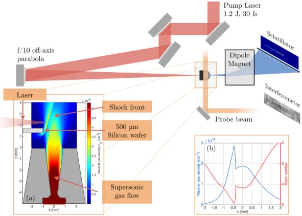
A Experimental methods 175 A.1 Laser System . . . 176
A.2 Gas target . . . 177
A.3 Plasma and electron beam diagnostics . . . 180
A.4 X-ray diagnostics . . . 182
B Numerical methods 191 B.1 Finite Difference Methods . . . 192
B.2 Test particle simulations . . . 194
B.3 Particle-In-Cell Simulations . . . 195
C Formulary 201
1
Introduction
From the earliest X-ray tubes to free-electron lasers the development of lightsources has been linked to the control of four different stages: Electron generation, acceleration, beam transport and finally radiation generation. The aim of this work is to apply the same staging philosophy to the emerging technology of laser-plasma lightsources, ameliorating the source by individual improvement of each element.
After an introduction to conventional accelerators and lightsources we will review qualitatively plasma-wakefield generation and radiation generation. Subsequently we briefly introduce some basic concepts of laser-plasma interactions in order to establish a foundation for the main chapters.
Contents
1.1 X-ray sources: from discharge tubes to free-electron-lasers . . . 2
1.2 Merits of laser-plasma technology . . . 6
1.2.1 The self-guiding, self-injecting and self-radiating regime . . . 7
1.2.2 Stages of laser-plasma lightsources and thesis outline . . . 9
1.3 Basic laser-plasma interaction and acceleration . . . 10
1.3.1 Vlasov-Maxwell system . . . 10
1.3.2 One-dimensional plasma waves . . . 11
1.3.3 Linear wakefields and particle acceleration . . . 12
1.3.4 Laser pulse propagation . . . 15
The discovery of the Higgs boson in 2014 is undoubtedly one of the greatest achievements in modern science. It was only made possible by the large hadron collider (LHC), a 26.7 kilometer long synchrotron, capable of accelerating particles to never preceded energies. The LHC is one of very few large accelerators in the public spotlight, yet particle accelerators and X-ray sources are nowadays ubiquitous in industrial, scientific and medical environments. Most of these small sources still rely on technology developed in the first half of the 20th century, when the development of industrial and scientific accelerators was still closely linked. This situation changed when scientific accelerators started to outgrow the size of university laboratories, needing own dedicated accelerator centers like CERN in Switzerland or DESY in Germany. This concentration to a few accelerator centers per country has drastically limited the accessibility to modern particle- and lightsources, despite their indisputable advantages for society. One of the central aims of laser-plasma technology is to fill this gap between large-scale facilities and common X-ray tubes.
1.1 X-ray sources: from discharge tubes to free-electron-lasers
The discovery of X-ray by Wilhelm Conrad Röntgen in 1895 [1] can be seen as the beginning of a new era in science. Yet from a technological point of view, the era of modern X-ray and particle sources commenced some years later, in the 1900s and 1910s. In fact, these two decades mark the timeframe that was needed to go from a machine that ’accidentally’ created X-ray to a device that was designed to do so.
The Crookes tube Röntgen used for his work creates electrons via field ionization of residual gas in a discharge. The freed electrons are then attracted by the anode where they emit radiation in form of bremsstrahlung and line excitation. Meanwhile the ions drift towards the cathode, where they free electrons via collision ionization. Electrons originating from the cathode can be accelerated to higher energies than the gas electrons and therefore radiate more when they eventually hit the anode. These early X-ray tubes (also called ion X-ray tubes or cold cathode Tubes) were not very efficient, hardly tunable and would stop working once the residual gas in the bulb was exhausted.
The modern X-ray tube design, which operates at higher vacuum and wherefore all electrons originate at the cathode, was developed later by Julius E. Lilienfeld in Germany [2] and William D. Coolidge in the United States [3]. In Coolidge’s X-ray tube [4] electrons are created by thermionic emission, heating a tungsten cathode to ª 2000±C. The thermionic emitter itself was already studied before, yet Coolidge was the first to achieve a vacuum good enough to reduce the effect of positive ions. Figure 1.1 shows Coolidge’s focusing X-ray tube No.147, which remarkably incorporates all main components of a modern X-ray source.
The principal component is the electron source, a closely wound tungsten spiral, the filament, which is heated by a current of 3 to 5 Amperes to temperatures of 1890 to 2540 Kelvin. Elec-trons are emitted from this spiral via thermionic emission, which is still the most common cathode type for this application. Then there is a focusing device, consisting of a cylindrical
1.1. X-ray sources: from discharge tubes to free-electron-lasers Hot Tungsten Cathode (25) Electron Source Molybdenum tube (21) Focusing Device High Voltage AC Accelerator Tungsten Target (2) Radiation generation
Figure 1.1 – Schematic layout of Coolidge’s X-ray tube from the original publication in 1913. The different parts of the tube are colored according to their function.
molybdenum tube that serves as electrostatic lens. Today this part is called the focusing cup; it is used to control the way the electrons hit the target anode. The gap between cathode and anode forms the accelerator, where a high voltage is applied to accelerate electrons in an electrostatic field. In Coolidge’s case up to 100 kV were reached, which is within the range of modern diagnostic X-ray generators (ª 20 ° 150 kV). Once electrons are accelerated, their en-ergy is converted into radiation when they hit the anode, which is tilted so X-rays are emitted outwards the bulb. The target is made of tungsten which produces, as a heavy element, more bremsstrahlung and provides good heat resistance. Nowadays tungsten remains most widely used, though sometimes alloys with better resistance to surface damage (e.g. 10% rhenium and 90% tungsten) or materials with specific emission lines (e.g. molybdenum or rhodium) are employed.
While the hot cathode tube was (and still is) perfectly adequate for most medical applications, scientists were interested in producing even harder X-ray. To do so, electrons had to be accelerated to higher energies, thus requiring field strength enhancement. Such could be 3
provided using Van-de-Graaff (1929) and Cockcroft-Walton (1932) generators, which allowed the acceleration of electrons to MeV level, yet at even higher field strength sparks would form.1 A major breakthrough in accelerator history was when Ising conceived (1925) and Wideroe demonstrated (1928) the principle of resonance acceleration. In lieu of electrostatic accel-eration, these machines operate with a time-dependent electric field and increase particle energies successively in several accelerating structures. With this principle Wideroe’s first 1 MHz radio-frequency linear accelerator (RF linac) managed to accelerate particles to twice the AC voltage using a drift tube and two grounded electrodes. His work inspired Ernest Lawrence in the United States to apply the resonance principle to a cyclic accelerating structure, thus increasing the particle energy during each revolution. However his cyclotron, which remains a widespread ion source nowadays, is limited to non-relativistic particle velocities in order to maintain synchronization and is therefore inadequate for electron acceleration. Instead, two other cyclic accelerator concepts were conceived and implemented shortly after: The betatron and the synchrotron [5].
The concept of a betatron is to accelerate electrons in a tangential electric field that is produced by a changing magnetic flux. In contrast to the cyclotron such a configuration can achieve relativistic energies. But, as Iwanenko and Pomeranchuk pointed out in 1944 [6], it will be ultimately limited by radiation losses, because particles are continuously accelerated in perpendicular direction in order to keep them on a circular orbit. At the same time Julian Schwinger also developed a theory for the radiation in a betatron [7], indicating that the radiation emission of a 100 MeV betatron should be peaked in the near infrared or visible part of the spectrum. In 1945 McMillan proposed the synchroton [8], which is in many ways a combination of Wideroe’s RF linac and Lawrence’s cyclotron. A crucial difference to preceding cyclic accelerator concepts is that the synchrotron cannot accelerate particles initially at rest, but instead needs an injector to provide electrons at already relativistic velocities. Shortly after the first demonstration of a synchrotron by Goward and Barnes [9], a more powerful 70 MeV machine was realized under the direction of Pollock [10]. It was his team that discovered the visible signal Schwinger predicted [11], now known as synchroton radiation.
The consecutive development of this 1st generation of synchrotons concentrated initially on reaching higher (over 1 GeV at ElettroSincrotrone in Frascati) and higher (6 GeV at DESY, etc.) beam energies. Later the development of storage rings provided higher beam currents and greater stability. However all these facilities were hybrid sources for high energy particles and radiation. The construction of facilities exclusively dedicated to the production of synchrotron radiation, like the SRS in Daresbury (UK) [12], marks the beginning of what is called 2nd generation facilities.
Though synchrotron radiation was discovered in cyclic accelerators, it was soon realized that also magnetic fields that alternate in the direction of motion could provoke transverse
1For high electric fields, field emission causes a local surface heating, which will then release particles into the
cavity. The gas is then ionized and as soon as the density rises sufficiently an arc form from the cathode to anode, leading to what is called vacuum breakdown.
1.1. X-ray sources: from discharge tubes to free-electron-lasers Electron Source Beam optics Accelerator Experiment Undulator
Figure 1.2 – Artistic view of a typical modern lightsource. The different parts responsible for electron generation and injection, acceleration, collimation and radiation generation are marked accordingly.
oscillation of electrons and therefore create radiation. For large oscillation amplitudes an observer will measure short flashes of radiation, whose Fourier transform corresponds to a wide radiation spectrum. With the same qualitative argument we see that the low amplitude undulator case will have a very narrow energy spectrum peaked around a fundamental fre-quency. This search-light model was introduced by Motz [13], who built the first undulator at the Stanford 100 MeV linac in 1953, producing 400 nm radiation [14]. Undulator radiation has a much better spatial and temporal coherence than Wiggler radiation, which is why modern synchrotrons are using mostly undulator configurations.
The high spatial coherence of synchrotron radiation also gave birth to a new generation of X-ray imaging techniques. For example, X-ray imaging using phase contrast has many advantages over conventional absorption contrast imaging [15].
In 1971 Madey proposed the free-electron-laser (FEL) [16], which was shortly later experimen-tally realized at Stanford [17]. The FELs mimics the concept of conventional lasers [18], but replaces the lasing medium with a relativistic electron beam. As operated in the IR or visible (3.4µm for [17]) an optical cavity can be set up using mirrors, with the light intensity growing by a few percent each passage.
However, in the extreme ultraviolet and X-ray regime it is not possible to set up a multi-pass cavity using mirrors. Instead an effect called microbunching becomes important. Mircobunch-ing means that the normally more or less equally distributed electrons, due to interactions with the radiation, drift into small bunches at a distance of one radiation wavelength each. This effect leads to coherent emission of all electron states and thus, laser-like properties. 5
Providing much higher gain than the conventional technique, spontaneous emission can be self-amplified within a single pass [19, 20].
First lasing in this SASE configuration was demonstrated in 2001 at the Advanced Photon Source, located at Argonne National Laboratory, [21] and emission in the Ångstrom regime was reached in 2011 at the SLAC Linear Coherent Light source [22]. Currently many projects are underway to built X-Ray FELs around the world, providing light at unprecedented intensities [23]. Also many facilities aim to replace the amplification of spontaneous emission by a seeded operation [24], which would provide even better temporal coherence. There are many ways such a seed can be implemented, e.g. by self-seeding [25], HHG seeding [26] or echo-enabled harmonic generation [27]. The typical layout of an FEL is shown in Fig. 1.2.
X-FELs are the pinnacle of accelerator and lightsource development, but even more, they are the result of a century of research and development around the same basic elements as Coolidge’s X-ray tube from 1913: electron source, accelerator, beam transport and radiation generation.
1.2 Merits of laser-plasma technology
Modern lightsources are not only extraordinary by means of their scientific value, but also due to their enormous scale. For example, the european XFEL consists of a 1.7 kilometer long accelerator and undulators of over 100 meter length [28]. And a typical 3rd generation synchrotron has a circumference of some hundred meters, with beam lines extending up to some tens of meters [29]. These large dimensions are dictated by technological limitations: First, the accelerating gradient in conventional accelerators cannot exceed ª 150 MV/m due to the vacuum breakdown limit. Second, the magnet arrays used in undulators cannot be made arbitrarily small, but have a minimal period of some millimeters.
So it is obvious that the spread of any technology based on synchrotron radiation, regardless its advantages, will be hindered by the limited accessibility of synchrotron sources itself. Laser-plasma lightsources may be able to surpass these limitations.
As an example, Figure 1.3 shows the results from an experiment on laser-driven electron acceleration with the ASTRAGEMINILaser in 2011 [30]. During the experimental campaign,
electrons were accelerated over ª 10 millimeters to GeV-energies and emitted synchrotron-like hard X-ray. The spatial coherence of these X-ray was indeed sufficient to acquire phase contrast radiographies of a specimen.
This experiment is representative for the state-of-the-art of laser-plasma lightsources at the beginning of this work. In the following we will therefore discuss qualitatively how this experiment worked and what particular challenges the technology still faces.
1.2. Merits of laser-plasma technology
Figure 1.3 – Top: Electron beam spectrum and X-ray signal observed in 2011 at the ASTRA
GEMINILaser. The laser plasma accelerator is operated in the transverse self-injection regime
and therefore the beam energy spread and divergence are elevated. Bottom: Propagation-based phase contrast images of a specimen at different angles from the same experiment.
1.2.1 The self-guiding, self-injecting and self-radiating regime
The main advantage of laser-plasma accelerators to conventional RF accelerator technology is that the plasma can sustain substantially higher fields, reaching TV/m. A laser-plasma accelerator (LPA) can boost electrons to GeV level energies over a centimeter, within a plasma cavity of some tens of micrometers. Also, due to the small dimensions of the cavity the accelerated electron bunches have a much shorter duration than in conventional facilities, usually in the femtosecond regime. In addition, the source size is in the micrometer range, hence the phase space volume of the beam is very small. Most early experiments on laser wakefield acceleration share on a fairly simple setup, relying in laser focussing and self-injection of electrons.
In this scheme a high power laser is focused onto a helium target, which is immediately ionized by the leading edge of the pulse. The intensity gradient of the focused laser leads to a net acceleration of particles away from high intensity regions. This so-called ponderomotive force scales as Fp/ h~A2i/∞, so the force is proportional to the mean square of the vector potential
h~A2i and thus acts in the same direction for both electrons and ions. Yet the widely different inertia of both species lead to disparate acceleration rates ¨xi on =mmi one ¨xe ø ¨xe, wherefore
charge separation is induced. Depending on the laser intensity this can range from a weak density perturbation up to a complete electron blowout, cf. Fig.1.4.
The transverse extension of the electron rarefaction is usually of the order of the laser spot size, while its length is restricted by the fact that electrons feel a restoring force from the ion background. The longitudinal extension is therefore limited by the (relativistic) plasma wavelength ∏p/p∞e/ne. The relativistic regime is reached if the laser potential is sufficient
accelerated electrons blow-out Secondary arches Laser propagation
Figure 1.4 – Snapshot from a simulation of laser wakefield acceleration. Electrons are injected in the back of the ion cavity formed behind the laser pulse (yellow). Due to initial transverse momentum during the injection the electrons perform betatron oscillations within the cavity, which leads to the emission of synchrotron radiation in direction of propagation.
to accelerate electrons to relativistic velocities, i.e. the normalized peak vector potential
a0= e A0/mec2> 1.
The ponderomotive expulsion and relativistic mass increase will also modify the dispersion relation, leading to relativistic self-focusing of the laser pulse [31]. As discussed in the preced-ing paragraph, fluctuation of the laser intensity due to this effect and variations of the local ion density will affect the cavity size. This alters the wake velocity and facilitates injection of background electrons into accelerating part of the cavity, a process known as self-injection. Once injected, electrons will gain energy from the potential inside the plasma cavity, which is close to parabolic in both longitudinal and transverse direction. Electrons with non-zero trans-verse momentum perform so-called betatron oscillations and emit broadband synchrotron radiation.
Apart from its poor shot-to-shot stability, the main disadvantage of this setup is that it is impos-sible to tune parameters like electron energy, charge, divergence and X-ray yield independently. For example, best X-ray results are achieved with electron beams of worst emittance, whereas mono-energetic, well-confined electron beams emit weak or non-measurable betatron radia-tion. Ergo, there is a need for more sophisticated solutions which allow to control different parameters of the laser-plasma source independently over a wide range. As in conventional lightsources this involves individual improvement of the stages of injection, acceleration, beam transport and radiation generation.
1.2. Merits of laser-plasma technology
1.2.2 Stages of laser-plasma lightsources and thesis outline
As laser-plasma accelerators operate in an already ionized medium, there is no need for a cathode to provide free electrons. Instead the challenge of the injection stage is to couple non-relativistic plasma background electrons to a plasma wave that propagates at a velocity close to the speed of light. The first experiment to achieve this in a controlled manner was presented in 2006 [32], and since then many different schemes have been proposed controlled particle injection. Chapter 2: Injection of this work focuses on experimental results on two injection mechanisms: injection due to cavity expansion in sharp density gradients and injection triggered by late ionization of higher charge states.
Once an electron is injected, it will be accelerated until either the laser-driver cannot sustain the wake anymore (depletion), or until electrons, having a different velocity than the driver, reach a decelerating region. In order to mitigate the effects of such dephasing, it has been proposed control the wake velocity via density tailoring. In Chapter 3: Acceleration we present analytical, numerical and experimental results on electron rephasing in the blowout regime using sharp density gradients. Also, we present experimental data that suggest electron acceleration beyond laser depletion due to wakefields driven by the electron bunch itself. A central drawback of laser-accelerated beams is their large divergence compared to con-ventional accelerators. If not collimated close to the accelerator exit, this can lead to severe degradation of the beam quality. Yet conventional beam optics are not powerful enough to achieve collimation on a millimeter scale. In Chapter 4: Beam Transport we will discuss how transverse wakefields can be used instead. Following a theoretical comparison of such plasma lenses to conventional beam optics, we present experimental results on electron beam focusing in a laser-driven wakefield lens. Furthermore we introduce the concept of electron defocusing via density tailoring, which can possibly amplify betatron radiation.
Speaking of which we come to the last stage: Chapter 5: Radiation Generation. Here we are going to discuss several methods to produce energetic photon beams with laser-accelerated electron beams. First we use bremsstrahlung conversion, similar to a conventional X-ray tube, to create MeV level radiation. This techniques has been demonstrated before, however the combination with ionization injection allows the - to our knowledge - first stable operation of such a source over hundreds of shots. Then we present results on synchrotron sources. First we investigate radiation generation via Compton backscattering. This section comprises a numerical investigation of different scattering geometries and experimental results using an all-optical scheme presented a few years ago. Finalizing the work, a larger part is dedicated to the improvement of betatron radiation, showing significant signal enhancement in density tailored plasmas and increased stability and polarization for ionization injected beams.
1.3 Basic laser-plasma interaction and acceleration
In this section we will establish a theoretical basis of laser-plasma interactions that we are going to build up on in the following chapters. Principal findings and definitions are also reviewed in the formulary.
1.3.1 Vlasov-Maxwell system
Most generally we are interested in the evolution of a particle distribution in space, velocity and time f (~x,~v, t). In a collisionless system, were particles are neither created or destroyed,
the continuity equation is valid
d f d t = @f @t + rx· µ@~x @t f ∂ + rp· µ@~v @t f ∂ = 0. (1.1)
In a electron-ion plasma, where the term @t~v is associated to the Lorentz force, we find that
evolution of the distribution function is given by the Vlasov equations
@fe @t +~ve·rxfe° e µ ~ E +v~ce £ ~B ∂ ·rpfe= 0 (1.2a) @fi @t +~vi·rxfi+ Zie µ ~ E +~vci £ ~B ∂ ·rpfi= 0 (1.2b)
coupled to the Maxwell-equations (cgs-units)
r £ ~B =4º~jc +1c@~@tE r· ~B = 0 (1.3a) r £ ~E = °1c@~@tB r·~E = 4ºΩ (1.3b) where Ω= e Z (Zifi° fe)d3p, ~j = e Z (Zifi~vi° fe~ve)d3p. (1.4)
This set of equations completely describes the behavior of a collisionless plasma. However, in order to extract useful information from it we need a way to solve these equations in some way. In particle-in-cell (PIC) codes the Maxwell equations are solved on a numerical grid. Meanwhile the Vlasov equation is solved continuously using a set of macroparticles, each usually representing ª fC of charge, to probe the distribution function. PIC codes are the most popular numerical solver for this problem and were used throughout this work, for example to obtain Fig.1.4. Yet they are numerically demanding and to get first intuition how the laser-plasma interaction works we will pursue a reduced analytical approach.
1.3. Basic laser-plasma interaction and acceleration
1.3.2 One-dimensional plasma waves
Let us now consider a simplified set of equations, treating the plasma like a fluid. For the moment we are not interested in the velocity but the density distribution, which can be obtained by integrating Vlasov equation over velocity space d3v, i.e.Rdtd f (x, v, t)d3v = 0. This
leads to the continuity equation of particle density, whose unidimensional form is written as
@tne(z, t) + @zj (z, t) = 0. (1.5)
It is common to describe the interaction in a frame moving at the phase velocity v¡along the
z-axis
ª= z ° v¡t and ø= t (1.6)
where the laser pulse appears only slowly varying in proper time ø and is nearly stationary. This quasi-static approximation allows us to express the differentials @ªand @øin terms of the
phase velocity of the pulse. Also, the electrodynamic Maxwell equations can be reduced to the electrostatic Poisson equation. As shown in [33] this leads to the reduced system
d2©(ª,ø) dª2 = °k2p(n0(ø) ° ne(ª,ø)) = k2p±n(ª,ø) (1.7) ±n = ne° n0= µ 1 1 ° vz/v¡° 1 ∂ n0, (1.8)
where we have expressed the current j = °enevz in terms of electron density ne and fluid
velocity vz. In the limit Ø¡! 1 we get then
1 k2p @2 @ª2©= ne n0° 1 = Ø 1 ° Ø= Ø 1 ° Ø ∞ ∞= pz ∞° pz. (1.9)
What is missing now is an expression for the particle momentum evolution pz in terms of the
potential. Such can be found from the relativistic Lagrangian for an electron in an external field ©(ª) [34]
L = ° q
1 ° Ø2
z+ ©(ª), (1.10)
which via Legendre transformation leads to the Hamiltonian2
H = ∞(1 ° ØzØ¡) ° ©(ª). (1.11)
As there is no explicit time dependence, the Hamiltonian is conserved H (t) = const., where the constant is defined by the initial conditions. For a particle initially at rest (pz(t = 0) = 0
2H= P · ˙ª ° L = p
z(Øz° Ø¡) ° L = °pØzz(Ø2z° ØzØ¡) + ∞°1° ©(ª) = °∞((1 ° Ø2z) + (1 ° Ø¡Øz)) + ∞°1° ©(ª) = ∞(1 ° ØzØ¡) ° ©(ª).
and ∞(t = 0) = 1) we find
∞= 1 + © + pz. (1.12)
It can be shown [33] that the transverse particle momentum p?follows the vector potential a and as the energy of a relativistic particle is given by ∞ =q1 + p?2+ p2“, we find
∞= 1 + pz! ∞2= 1 + 2pz+ p2z= 1 + p2?+ p2z= 1 + a2+ p2z (1.13)
and therefore we find an equation for the longitudinal momentum
pz=1 + © 2 µ 1 + a2 (1 + ©)2° 1 ∂ (1.14) From (1.12) we know that 1 + © = ∞ ° pzand so we can combine (1.9) and (1.14) to the
non-linear one-dimensional plasma wave equation
@2 @ª2©= 1 2 µ 1 + a2 (1 + ©)2° 1 ∂ k2p. (1.15)
In the upper frame of Fig.1.5 solutions for the potential ©, the electric field E and the density perturbation ±n based on (1.15) are shown. The plasma wave is excited by a sin2-envelope laser pulse with a duration of ø0= ∏p/2c0. The field strength is expressed in units of the
electron rest mass mec2, which is convenient to distinguish between the linear non-relativistic
regime and the non-linear relativistic regime. In this case the normalized peak vector potential
a0= e ~A0/mec has a value a0= 0.2, i.e. the laser pulse induces only weak density perturbations
and the transverse electron motion remains non-relativistic (p?ø mec2).
1.3.3 Linear wakefields and particle acceleration
We have seen in Fig.1.5 that the electric field in the wake of the pulse seems close to sinusoidal. Assuming a weak excitation (a ø 1 and © ø 1) the wave equation (1.15) reduces to
µ @2 @≥2+ k 2 p ∂ ©= k2pha 2i 2 . (1.16)
Here ha2i/2 is the ponderomotive potential of the pulse, which represents the average effect of the field integrated over a laser cycle. In a similar way one defines the one-dimensional ponderomotive force Fp= @ªha2i/2 as the net effect of the Lorentz force over one laser period.
Equation (1.16) is an inhomogeneous Helmholtz equation and it can be shown [35] that for a laser pulse at position ª0
©=a
2 0
1.3. Basic laser-plasma interaction and acceleration
Figure 1.5 – Upper frame: Solution of the one-dimensional wakefield equation for a pump pulse with a peak field strength a0= 0.2 and a sin2-shaped envelope with FWHM of ∏p/2.
The laser induced density perturbation (linear plasma wave) is marked in green, while the longitudinal electric fields are in blue and the potential is plotted in yellow. For visualization purposes the sign of ±n is flipped and both Ezand © are plotted in arbitrary units.
Lower frame: Solution of the hamiltonian for the above potential. The injection (discussed in Ch.2) is marked in yellow. We define an electron as injected into the wake as soon as it co-propagates with the wake, i.e. pz= m∞¡c2. During the acceleration process (shown in blue),
the electrons gains significantly in energy, until it has advanced over half a plasma wavelength (linear dephasing length), when it starts to experience decelerating longitudinal fields (red). Note that the above solution is normalized in terms of the plasma density, meaning that it is just dependent on the pump pulse and not on the density anymore.
Here cenvis a coefficient that reflects how well the pulse envelope couples to the wakefield.3
From (1.17) we see that the electric field Ez= °@z©evolves according to
Ez=
a20
4
mc!p
e cenvcos[kp(ª ° ª0)], (1.18)
which is indeed sinusoidal. Assuming a resonant pulse (cenvª 1.5), we find that the maximum
field strength is of the order of |Ez,max| ª a2 0 3 £ 96 q n0[1018cm°3] GV/m. (1.19)
This means that in the above scenario with a0= 0.2 and assuming a plasma density of n0=
1018cm°3the electric fields reach over 1 GV/m. This is an order of magnitude higher than the
strongest fields achievable in conventional RF cavities, whence the attractiveness of plasma waves for acceleration. As we will discuss in Sec.3.2 the fields can reach even beyond TV/m in the highly non-linear regime.
As we have already derived an equation for the Hamiltonian and the wake potential, we can use classical mechanics to calculate the energy gain of a particle with a given initial momentum
pz= ∞Øz. The solutions are plotted in the lower frame of Fig.1.5.
If Øzø Ø¡the electron gets periodically accelerated and decelerated. In the co-moving frame
the electron travels in opposite direction to the laser (i.e. right-to-left) and so the interaction length in the laboratory frame is of the order of some plasma wavelength ∏p. In contrast
an electron with a much greater momentum pz> m∞¡c2would catch up, co-propagate and
then eventually outrun the plasma wave. As the electrons move into the same direction, the interaction length is of the order ∏p/(Øz°Ø¡) ¿ ∏p. This allows the particle to gain significant
energy from the plasma wave. However, in this case we only accelerate particles that are already relativistic.
A special case is the regime in between, within the separatrix. Here particles are originally slower than the driver, but once they experience the wakefield, they are accelerated and catch up, i.e. Øz> Ø¡.4In the following Chapter 2: Injection we are going to discuss in detail how
this is realized experimentally. Once injected, electrons are co-propagating, which means that the interaction length - and therefore the acceleration length - is substantially increased. However, Øz> Ø¡implies that the electron advances with respect to the driver and it will
ultimately reach a region of inverse, decelerating electric field. Such dephasing is the limiting
3Depending on the pulse shape the coefficient is
cenv= [1 ° (kpæz/º)2]°1sin(kpæz) (sin2pulse)
cenv=
q
º/4log(2)(!pø)exp[°(!pø)2/16log(2)] (gaussian pulse)
1.3. Basic laser-plasma interaction and acceleration
factor of most laser-plasma accelerators and in Chapter 3: Acceleration we will discuss how to mitigate phase detuning by changing the driver velocity.
1.3.4 Laser pulse propagation
Both the injection and the acceleration processes are closely linked to the phase velocity of the plasma wave v¡. At a constant plasma density v¡is entirely determined by the laser driver
and it will therefore be useful for the following chapters to introduce some concepts of laser pulse propagation in cold collisionless plasmas.
In such a plasma the phase and group velocity are given by
vph=!k0 =c0
¥ and vg=
d!0
dk = ¥c0, (1.20)
where ¥ =q1 ° !2p/!20is the refractive index. If the plasma frequency !pis equal or higher
than the laser frequency !0, the plasma is called overdense and the laser gets reflected. The
density at which this transition occurs is called the critical density nc. In contrast, for an
underdense plamsa (neø nc) we can approximate ¥ ' 1 ° !2p/2!20. While this relationship
is quite accurate for linear wakefield generation, intense laser pulses enter the regime of relativistic optics (a0> 1). As we have mentioned in the previous section, the plasma frequency
changes at relativistic intensities. This modifies the refractive index to ¥ ' 1 ° !2p/2∞!20.
The average momentum gain comes mostly from transverse acceleration a0= p?, so ∞ ' ∞?q1 + ha20i.
The laser induced particle motion will also locally modify the plasma density as n = n0+ ±n,
which is the ponderomotive blowout. Including both effects we find [36]
¥' 1 °1 2 !2p !20 √ 1 +±nn 0° ha02i 2 ! , (1.21)
where we assumed again weak perturbations (±n ø n0) and field strength (a0< 1).
The change of the refractive index creates a lensing effect, leading to self-focussing of the laser pulse. According to its physical origin the ±n component is also called ponderomotive self-focusing [37, 38], while the a20term is called relativistic self-focusing [39, 40]. The latter is predominant for weak drivers. For a gaussian beam of waist w0we can equate the beam
diffraction near focus (@2w/@z2º 4/!2
0w03) with the relativistic self-focusing term (@2w/@z2'
°(a0!p/!0)2/8w) and find that the spot size evolves according to [36]
@2w @z2 = 4c02 k02w03 µ 1 °321 a20w02!2p ∂ . (1.22) 15
Figure 1.6 – Particle-In-Cell simulation of the evolution of a laser pulse of 800 nm wavelength (no chirp) in a plasma. The pulse is focused to 18 µm waist (ª f/18), which corresponds to a Rayleigh length LR ª 1.26 mm in vacuum. The focus is at the entrance of a gas cell at
z = 0.1mm. From this point the plasma density rises linearly from zero to 8.0 £ 1018cm°3at
z = 1.0 mm and remains constant beyond this point.
The left side shows the beam waist and duration for different propagation distances, while the plot on the right side shows the evolution of the on-axis field strength. As the simulation window advances at c0the laser velocity can be measured as an angle. In this representation
the different velocities of the pulse front and the etching are clearly visible.
This equation indicates that the spot size will diminish if the right-hand side is negative, i.e.
a20w2> 32/!2p. The term a20w2is proportional to the laser power and we can therefore define
a critical power Pc= mec05 e2 !20 !2p ' 17 !20 !2p GW (1.23)
for which the laser will undergo self-focusing [40]. Importantly the critical power is inversely proportional to the plasma density.
Self-focusing as described above would be, in principle, a self-amplifying instability. But in reality self-focusing only grows until the ponderomotive self-focusing term takes over in the non-linear regime. This term is then ultimately counteracted by the recoiling force of the ion background. Many experiments operate in this regime, where a quasi-stable equilibrium exists. Once the laser has reached this matched spot size, it can be guided over several Rayleigh lengths at relatively stable intensity [41].
To illustrate the complex pulse evolution, Fig.1.6 shows the results of a Particle-In-Cell sim-ulation of the propagation of a laser pulse in a plasma. Up to z = 1mm we observe how the
1.3. Basic laser-plasma interaction and acceleration
laser self-focuses. At the same time the pulse length reduces. This is a consequence of the ponderomotive ±n/n0term, which leads to a reduction of the plasma density in the rear part
of the pulse. Accordingly the rear part propagates faster than the front, compressing the pulse (cf. for example z = 0.7mm and z = 1.0mm).
But we also observe that from z = 1mm to z = 1.5mm the peak intensity shifts backwards. This so-called etching is the typical signature of pump depletion. This term is important to ensure energy transfer to the wake and it also antagonizes the defocusing effect of the longitudinal ponderomotive force at the pulse front. An analysis based on the one-dimensional wave model (1.15) finds that the etching velocity is given by
vetch'
!2p
!20c0. (1.24)
Interestingly this value is independent of the wake excitation term a0and amplitude @n, which
cancels out in the derivation [42]. Even this velocity is derived for the non-linear 1D wave model, 3D Particle-In-Cell simulations [41] and experiments [43] find that the estimations from the Decker model are quite accurate, even beyond its initial validity region.
The phase velocity of the plasma wake, given by the propagation velocity of the plasma wave excitation is therefore of the order of the laser group velocity minus the etching term, i.e.
v¡' vg° vetch' √ 1 °32! 2 p !20 ! c0. (1.25) 17
2
Injection
This chapter concentrates on the problem of particle injection into a propagating accelerating field. First we discuss conventional solutions and their performance, followed by a qualitative overview of laser-plasma injection techniques.
All experiments performed for this work relied on three main injection schemes, namely self-injection, density downramp injection and ionization injection. We will discuss these methods and give examples for beam quality obtained using injection in sharp density transitions and ionization injection.
Contents
2.1 Conventional injectors . . . 20 2.1.1 Cathodes and electron guns . . . 20 2.1.2 Conventional linac as injector of LPAs . . . 22 2.2 Laser-plasma injection schemes . . . 22 2.3 Self-injection . . . 25 2.4 Density transition injection . . . 29 2.5 Ionization injection . . . 33 2.5.1 Strong field ionization . . . 33 2.5.2 Conceptual idea . . . 36 2.5.3 Ionization injection in pure high-Z gases . . . 37 2.5.4 Ionization injection in gas mixtures . . . 42 2.6 Conclusions . . . 44
As discussed in the introductory chapter linacs, cyclotrons, synchrotrons and also laser wake-field accelerators are types of what is called resonance accelerators. In such an accelerator the accelerating field is time-dependent and particles need to stay in phase for sustained energy gain. As a consequence it is necessary that particles are injected into the accelerator stage with a propagation velocity veclose to the phase velocity v¡of the field.
In conventional accelerator facilities the creation and pre-acceleration of the electron beam is done using a separate device, called the electron gun. An electron gun consists of a cathode that emits electrons, which is coupled to a DC or RF field. In this field, electrons are acceler-ated to mildly relativistic energies, from whereon they can be injected into the accelerator. While this works well for conventional accelerators, injection into the a plasma wakefield is challenging due to the small cavity size (∏pª 10°5m) [44, 45, 46].
Instead, laser-wakefield accelerators rely on the injection of electrons from the plasma itself. Numerous variants of such injection schemes exist, but in an illustrative way we can divide them into two main approaches. The first one is analogous to the electron gun in conventional accelerators, i.e. to accelerate the plasma electrons to relativistic energies. An example of this is optical colliding pulse injection [32]. The second method is to slow down the wake by inducing an expansion of the cavity. As the wake size depends on the plasma density neand
the laser intensity a0, variations of these can therefore induce injection. Such variations can
happen within the plasma itself, e.g. from self-focussing of the laser pulse. Or can be created intentionally e.g. with a density downramp.1
2.1 Conventional injectors
As we have seen before, the main task of the injector is to provide electrons and manage to inject them in phase into a resonance accelerator. In a plasma accelerator the first task this is straightforward as the plasma itself serves as supply of free electrons. However in solids the situation is different, as electrons are still bound and first have to be freed. In fact, the electron extraction at the cathode already defines many beam parameters for the subsequent acceleration.
2.1.1 Cathodes and electron guns
In solids there are three main approaches to free electrons, cf. Fig.2.1. One is to heat the solid so the electron energy distribution extents beyond the binding potential, known as thermionic emission [47, 48]. Another way is to apply a strong electric field and therefore increase the
1The central aim of this chapter is to familiarize the reader with different injection methods and to evaluate
their performance for coupling them to subsequent stages of a laser-plasma lightsource. An extensive discussion
of our results on controlled injection schemes will be published in E.GUILLAUME, Control of electron injection
2.1. Conventional injectors ingoing photon scattered electron outg oing p hoton
Field
Emission
Thermal
Emission
Photo-
emission
Figure 2.1 – Illustration of the principle of the three main cathode types: Field emitters, thermionic emitters and photocathodes.
tunneling probability of electrons to escape. This process is known as field emission [49, 50].2 Third, electrons can gain energy to escape from photoelectric absorption [51, 52].
Thermionic and field emitters are widespread due to the simplicity and robustness of the setup. However, the electron bunches created in such devices have a long duration (>100 ps) and are difficult to control. On the contrary, in photoemitters the electron properties are determined by the exciting laser [53], which means that very short pulses with low emittance can be created.
The two main families are semiconductor and metal photocathodes. Semiconductor cathodes can provide high current beams and usually have a good quantum efficiency in the visible, thus allowing the usage of standard (green) lasers. In contrast they require a very good vacuum quality for operation and have the shortest lifetime among all cathode types. Metal photocathodes are much more durable and due to their faster response time (femtoseconds vs picoseconds) they can be used to produce ultrashort electron bunches. Their principal drawback is that metals have a work function of some eV (e.g. 4.65 eV for copper), which requires UV light to free the electrons.
Once electrons are freed they have to be boosted to relativistic velocities. Note that at the moment of emission they are still non-relativistic, so space charge effects are much more important than in any other part of the accelerator. Therefore beam optics are used to shape the beam, while either DC or RF fields are used to accelerate it towards subsequent accelerating sections.
For lightsources the whole range of electron gun types is employed, depending on the specific needs of the facility. For example, at ESRF a thermionic gun produces either 1ns-1nC or
1µs-10nC bunches at an emittance of 35 and 15 mm.mrad, respectively. The bunch is then
accelerated to 85 keV in a DC field and coupled to RF cavities [54]. In contrast, the LCLS free electron laser requires short low-emittance beams. It therefore uses a copper photocathode that is illuminated with a 255 nm UV laser. This cathode is capable of producing up to 1nC
2Field emission is conceptually related to field ionization we will discuss later in this Chapter. Also, it is one of
the primary causes of vacuum breakdown which limits conventional accelerator field strengths, cf. Ch.3.
bunches at 10ps duration with an emittance of 1.2 mm.mrad, which are pre-accelerated in a 115 MV/m RF cavity [55].
2.1.2 Conventional linac as injector of LPAs
Laser-plasma acceleration was demonstrated for the first time in the early 1990s using external injection of electrons into a laser-plasma beat wave. For example the UCLA group showed trapping of 2 MeV electrons inside a wake with ∞¡= 33. In these experiments electrons were
accelerated in a gradient of ª 2.8 GeV/m up to 30 MeV. Such plasma beat wave experiments used picosecond laser pulses, with injection electron beams of ª 10 ps in the case of [56]. Additionally there was a jitter of ±50 ps between both laser and electron beam, leading to an unstable operation with strong energy variations.
However, since the early 2000s another acceleration scheme, resonant laser wakefield acceler-ation prevails the field of laser-plasma acceleracceler-ation. In this scheme it is even more difficult to inject the beam as one needs femtosecond bunches and very low jitter.
Due to the short pulse duration, photocathode based injectors are best suited to be coupled to a laser wakefield accelerator. This is for example one of the goals of REGAE (Relativistic Electron Gun for Atomic Exploration) at DESY. Here a Cs2Te p-type semiconductor photocathode
is used as source for low charge (ª 1 pC) electron bunches. Including a section for beam compression, this gun should provide 10-15 fs beams at 3-5µm RMS width and 0.3 mm.mrad emittance. With a final energy of up to 5 MeV, such an accelerator could be used for external injection in wakefields. However, due to the very low charge produced, RAGAE and similar facilities are principally intended for basic research on wakefield acceleration rather than for applications.
2.2 Laser-plasma injection schemes
As we have seen in the preceding section it is challenging to use conventional electron sources as injector for a wakefield accelerator. An easier way is to use electrons from the plasma itself. As discussed previously the main requirement for injection into a wakefield is that the electrons can maintain phase, which basically reduces to the simple condition that vz> v¡at
the rear part of the wake.
For the fluid model that we introduced in the first chapter the condition vz> v¡means that
part of the fluid elements is moving faster than the wave, i.e. the wave brakes. Earlier we have seen that the static Hamiltonian for this system is H = ∞(1 ° ØzØ¡) ° ¡. In the moment of
injection (vz= v¡), hence H = 1°¡i n j. Momentum is conserved, so to trap a particle initially
2.2. Laser-plasma injection schemes
non-relativistic wavebreaking threshold in a cold plasma [57]
E0'
mec!p
e = 96 GV/m £
q
n0[1018cm°3]. (2.1)
The above expression is only a rough estimation, as electrons are moving at a speed close to the phase velocity during injection, so a relativistic treatment is unavoidable. This effect becomes more important the faster the wave moves and increases the cold wavebreaking limit by a factorp2(∞¡° 1).[58]
Earlier we derived the maximum field strength in the linear wakefield regime (1.19), which we can now be rewritten as |Ez,max| ª (cenva20/4) £ E0. The linear regime is only valid for
non-relativistic field strength (a0ø 1), so it is apparent that |Ez,max| < E0, i.e. wavebreaking
cannot occur in the linear wakefield regime.
Self-injection
Instead non-linear plasma waves have to be excited in order to achieve electron injection via wavebreaking. This was first demonstrated in 1995 [59] at the VULCANlaser which delivered 0.8
ps laser pulses at peak intensities of up to a0ª 1.9. In this experiment plasmas with densities ne> 1019cm°3were used. As the pulse is much longer than the plasma wavelength cø0¿ ∏p,
it is self-modulated and excites a non-linear plasma wave. Wavebreaking lead to continuous
self-injection of electrons into the wake and the acceleration resulted in Maxwellian electron
spectra extending up to 44 MeV.
The advent of high power Ti:Sapphire systems with durations below 100 fs allowed for the first time to operate in a regime of resonant wake excitation (cø0ª ∏p) while guiding the
pulse beyond the Rayleigh length via self-focusing (P > Pc= 17!20/!2pGW). This permitted to
accelerate electrons up to ª 200 MeV [60], yet the spectrum was still Maxwellian.
In 2002 it was theoretically predicted that acceleration in the highly non-linear broken-wave regime could lead to beams with monoenergetic features [61]. The publication raised a lot of attention and became widely known as bubble regime. Even the simulated laser param-eters (a0= 10, 33 fs) were beyond the experimental means of the time, first narrow energy
spread beams were demonstrated experimentally shortly later [62, 63, 64]. Three different mechanisms were suggested to explain the low energy spread in these experiments: (a) Tem-porally cavity expansion induced by self-focusing of the laser pulse, (b) inhibited continuous injection due to beam loading and (c) dephasing induced energy spread reduction. In most experimental conditions a combination of all three effects will occur. We will discuss (c) in
Chapter 3: Acceleration and concentrate for the moment on (a) and (b).
The wake that forms behind the laser scales withpa0/ne. So self-focusing of the laser will
increase the wave period. This expansion has two effects. Firstly, it will reduce the phase velocity of the wake as function of the phase ¡ within the wakefield. Secondly, for a rapid
expansion the symmetry between accelerating and decelerating field is temporarily broken, meaning that an electron with proper timing can gain net energy from the wake due to the expansion and gets injected. However, this requires proper timing and hence results in a short injection length. Also, once particles are injected into the wake they shield the ions and reduce locally the wakefield, a process also known as beam-loading.
We distinguish two regimes of such self-focusing driven self-injection [65]. If the initial laser intensity is highly relativistic (a0&3 ° 4), ponderomotive expulsion leads to a formation of
an ion cavity behind the laser pulse. In this case electrons can only get trapped transversely, traveling along the sheaths. To date this transverse self-injection is the most common injection mechanism in laser wakefield acceleration. At lower weakly relativistic intensities (a0ª 1 ° 3)
there remains charge on axis, which can then get injected via longitudinal self-injection.
Controlled injection schemes
Self-injection into the wake provides a simple method to trap electrons in a laser-wakefield, however it is not directly controllable and subject to strong shot-to-shot fluctuations. During the last years a number of controlled injection schemes have been proposed or demonstrated that extent the reliability and tunability of the source.[66]
As the wake scales also with the plasma density, alternatively to increasing the laser intensity a cavity expansion can be induced by a reduction of the plasma density. Again, for a weak long gradient the main effect is the reduced phase velocity, leading continuous down-ramp
injection [67, 68]. In contrast, for a sharp transition, as for example possible to create with
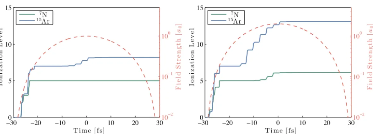
shocks, the asymmetric acceleration leads to a short well-located injection [69, 70, 71]. Another way to gain net energy from the wakefield and facilitate injection is via late ionization. To do so a high-Z gas (usually nitrogen or argon) is used to create the plasma. While the outer shells are ionized by the pulse front, the deeper ionization states are only reached close to the peak of the pulse. Electrons are therefore born late into the wake and ideally experience only the accelerating part of the wake [72, 73, 74]. This ionization injection leads to continuous injection along the axis, so the beams have a high charge but also large energy spread, as demonstrated for example in [75, 76].
A conceptually similar proposed injection scheme is cold-optical injection [77]. Here a second laser pulse leads to a spatially periodic and time-independent beatforce. This force would then freeze the longitudinal electron motion during the decelerating phase of the wake, which again allows the electron to gain net energy from the wake and get trapped.
Alternatively a beat can be used to increase a particles momentum, thus speeding up the particle to facilitate injection. This colliding pulse injection has been demonstrated in 2006 [32] and it was shown that the method not only allows to produce monoenergetic particle beams, but furthermore the energy could be tuned by varying the injection position. Also, the
2.3. Self-injection
phase-space volume occupied by injected electrons can be varied by changing the scattering pulse energy [78].
Let us now enlarge upon those injection schemes that we used for this work, i.e. self-injection (Sec.2.3), density downramp injection (Sec.2.4) and ionization injection (Sec.2.5).
2.3 Self-injection
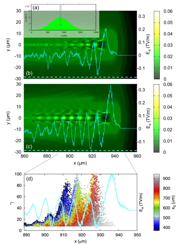
To date, self-injection remains probably the most common type of injector used in laser-wakefield acceleration, as it requires no additional external measures. But even self-injection is the simplest type of injection to be set up in an experiment, it is a physically complex phenomenon which can occur under many different circumstances, e.g. in the quasi-linear and the non-linear regime, for both evolving [79, 80, 81] and non-evolving bubbles [82]. To illustrate this, Figures 2.3 and 2.4 show the results of different Particle-in-Cell simulations. The only changing parameter is the plasma density profile, which as we observe, greatly changes the simulations’ outcome.3
All simulations have in common that the laser pulse evolves during propagation and after ª 1 mm it reaches a stable spot size. This matched field strength is found to scale about linearly with the plateau density. At high plasma densities the wakefields that build up behind the laser exceed the wavebreaking threshold. In this case electrons gain longitudinal momentum that exceeds the phase velocity (cf. Fig.2.2) and continuous electron injection begins. The lower the plasma density, the later this wavebreaking initiates. At ne = 1.5 £ 1019cm°3
injection starts around 0.7 mm into the jet, while at 1.0 £ 1019cm°3it is delayed to ª 1.5 mm
(not shown here) and at 0.8£1019cm°3no electrons are injected at all. This changes however as
we modify the density ramp. If the density increases much faster than self-focusing can react, the bubble undergoes important laser-induced fluctuations. An expanding cavity will facilitate injection and via this mechanism electrons can still get injected into the wake. However, in this case injection occurs only over a short distance, leading to a quasi-monoenergetic electron beam, cf. Fig.2.4. Also depending on the laser intensity, electrons can be either injected transversely or longitudinally.
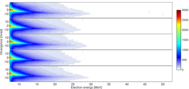
So we have seen that self-injection heavily depends on the laser and plasma evolution. Some regimes are more sensible to fluctuations than others, e.g. low charged injection close to injection threshold is usually more stable in terms of accelerated charge, energy, divergence and pointing, than high density operation, see e.g. [83, 84]. For the aforementioned reasons it is difficult to define a ’typical shot’ for self-injection as a whole. Instead we will give some examples of experimentally observed spectra in the following.
3The other simulation parameters are as follows: Simulations are performed using CALDER-CIRCat a resolution
¢z = 0.3k°10 , ¢r = 1.5k°10 and ¢t = 0.96¢z, with a simulation mesh size nz£ nr= 1500 £ 250. The laser pulse is
identically initiated as well, with parameters similar to SALLEJAUNE(duration of 30 fs, waist of 11.5 microns and
peak potential a0= 2.5).
Figure 2.2 – Particle-In-Cell simulation with CALDER-CIRCof self-injection, with macro
parti-cles projected onto the density map. The upper frame is normalized to the wake phase velocity
∞¡= !0/!p. In this representation it is clear that injected particles are faster than the wake
and we can see those which are going to be injected soon in the back of the bubble. In the lower frame the momentum is color-coded in MeV. This illustrates the broadband nature of the electron spectrum, with highest energies at the head of the beam. Pixel area corresponds to the weight, color and transparency to the momentum.
2.3. Self-injection
(b)
(d)
(f)
(a)
(c)
(e)
Figure 2.3 – Particle-In-Cell simulation with CALDER-CIRCof self-injection for two different
densities, 1.2 £ 1019cm°3on the left and 1.5 £ 1019cm°3on the right. Figures (e) and (f) show
the density profiles (solid green) and the corresponding laser pulse evolution (red). The beam spectrum is represented with a logarithmic colorscale, with a charge difference of 106between
yellow and dark blue. We see that increasing the plasma density anticipates injection. (a-b) shows the electron density and laser pulse just before injection begins. In (c-d) we see how electrons have been continuously injected into the cavity.
Figure 2.4 – Particle-In-Cell simulation with CALDER-CIRCof self-injection at 0.8 £ 1019cm°3.
On the left the density ramp is 0.5 mm long, as in Fig.2.3. Clearly this density is below the self-injection threshold and no electrons are accelerated. But for a steeper density ramp (0.125 mm) we observe injection at around z ª 0.5 mm.
Longitudinal self-injection
Longitudinal self-injection occurs at moderately high laser intensities (a0ª 1 ° 3), when the
laser forms a wake, yet not all electrons are ponderomotively blown out. In this case it is possible for electrons to get injected on axis, usually during laser self-focusing, when cavity expansion facilitates injection. Longitudinal self-injection is limited to the quasi-linear regime and thus only happens early during the laser propagation. It therefore leads to higher energies than transverse self-injection. In contrast the injected charge is much less, typically some pC. Longitudinally injected beams have usually a divergence of some millirad and a reasonable shot-to-shot stability. Longitudinal self-injection will be used in Sec.4.4.3, cf. Fig.4.11.
Transverse self-injection
In contrast, transverse self-injection takes place in the blow-out regime, when sheaths elec-trons get trapped during an expansion phase or when the wakefields exceed the wavebreaking threshold. Most experiments that use self-injection operate in this regime and it is characteris-tic that electrons that originate from this mechanism have higher transverse momentum. The transition between both self-induced self-injection processes is related to the laser field strength, which is usually defined by self-focusing and therefore density dependent. At lower densities, below the transverse self-injection threshold, only longitudinal injection takes place. However, at higher densities (or longer propagation lengths) transverse self-injection will dominate by far, as this regime allows injection of some hundred pC into the wake. It has been shown that when operated close to the injection threshold transverse self-injection can lead to quasi-monoenergetic beams. Experiments relying on transverse self-injection are discussed in sections 3.4.4, 5.4.2 and 5.5.3.