Academic Year 2015/2016
The Democratic People's Republic of Algeria
Ministry of Higher Education and Scientific Research
Thesis of End Studies
Presented at
Echahid Hamma Lakhdar University-El Oued
Faculty of Technology
Department of Electrical Engineering
In order to obtain a diploma with
ACADEMIC MASTER
Degree
In Telecommunications
Presented by
HATHROUBI Hadjer and MERAGHNI EL-Bachir
Theme
Design of ZBLAN photonic crystal fiber with nearly
zero ultra-flattened chromatic dispersion
Defend at 26/05/2016. In front of the jury composed of:
Ms. BOUKAOUS Chahra
Associate professor
President
Mr. MEDJOURI Abdelkader
Associate professor
Rapporteur
I
Appreciation
First of all, we start by addressing our most sincere thanks to our research
promoter Mr. MEDJOURI Abdelkader, who has proposed this very interesting topic.
This achievement could not be carried out in large part due to his kindness and
cooperation. We are also grateful to him for his unfailing availability and dynamism
during the entire duration of this thesis and to the scientific and pedagogical skills
of it’s frame without which this work would not have emerged.
Our thanks also go to our colleagues with whom we shared the section, finally
Dedication
We dedicate this modest work:
To Our parents. May god give them good health and long life.
To our brothers and sisters,
For all family members and friends,
And to all those who contributed to the realization of this theses ,we say
thank you.
III
Abstract
The research work reported in this thesis deals with the analyzing and
optimizing the linear and nonlinear properties of ZBLAN circular lattice photonic
crystal fiber (CL-PCF),
in the aim of their applications in optical telecommunications, also
the different optical properties such as the confinement loss, the chromatic
dispersion, the birefringence and the effective mode area are calculated and
optimized by using
the finite difference frequency domain method (FDFD). The
simulations results shows that with optimizing their opto-geometrical parameters,
the PCF can exhibit interesting properties that couldn't be achieved with
conventional fibers. Considering the numerical modeling, by using the nonlinear
Schrödinger equation (NLSE) to describe the pulses propagation within the PCF ,
we show the possibility of generating of supercontinuum by exploiting the nonlinear
effects that occur during the propagation of ultra-short pulses (femtosecond) in the
PCF.
Keywords
Photonic crystal fiber, ZBLAN, Finite difference method frequency domain,
Nonlinear Schrödinger equation, supercontinuum generation.
Résumé
Le travail présenté dans ce mémoire concerne l'étude et l’optimisation des
propriétés linéaires et non linaires des fibres optiques microstructurées (FOM) à
base de
ZBLAN trouée avec une configuration circulaire, en vue de leurs utilisations
dans les systèmes de télécommunications optiques et les différentes propriétés des
FOM telles que les pertes par confinement, la dispersion chromatique, la
biréfringence et l'aire effective de mode sont analysées et optimisées en utilisant la
méthode de différences finies dans le domaine fréquentiel FDFD. Les résultats de
simulations montrent qu'avec une bonne optimisation de leurs paramètres
opto-géométriques, les FOM peuvent présenter des propriétés de propagation singulières,
inaccessibles aux fibres conventionnelles. La modélisation numérique, quant à elle,
est basée sur la résolution de l'équation non linéaire de Schrödinger (NLSE), nous
montrons la possibilité de générer des supercontinuums exploitant les effets non
linéaires se manifestant dans les FOM lors de la propagation des impulsions
ultra-courtes (femtoseconde).
Mots clés
Fibre optique microstructurées, ZBLAN, méthode de différences finies dans le
domaine fréquentiel, Equation non linéaire de Schrödinger, génération du
supercontinuum.
V
صخلم
ذذذذه
ذذذذملا
ت
ذذذذ لا دذذذذ لا ذذذذئ مخر ذذذذنا ة اردذذذذنت
ذذذذ ذذذذ غلا ر
ل
دذذذذ للأ
ذذذذ بلا
ت دتذذذن كلا تاذ
ذذذذضلا
PCF
)
ا تذذذنإب
دذذذذئز
ZBLAN
ذذذذع دذذذض ع
دذذذئز
ذذذذسلا
س
،
ل
ذذذذه
ادذذذ ذذذم دذذذهق ب ت
ا
لإ
ذذذ ذذذ ت ملا ذذذ بلا دذذذ لا ذذذنا ة دذذذض رر ا ذذذ بلا ت دذذذ ت
د ذذذض
ذذذقد لا
ر ، خ ذذذ لا لتذذذشتلار ،
لإا
دذذذسكخ
لا
ر رةزم
منذذذ ل ذذذ ة لا ادذذذسملا
ده ر ذذذب ذذذتلا
ذذذكت
ب ذذذسح
ب ذذذذئ من ر
إ
ذذذذم ةر ذذذذحملا ير ذذذذ لا ذذذذق ة ا تذذذذن
لا
ادذذذذ م
زذذذذت هلا
) ةة ذذذذتلا
FDFD
ا
ر
لذذذذتبثر
ذذذذ ذذذذخر دذذذذ دحملا م دذذذذتخ
ت إ
د
ذذذذ ر
ل
ذذذذ لا دذذذذ
ذذذذ بلا
ذ
تا
ذذذذكم ، ذذذذن نهلا بدذذذذ لا
ل
ذذذذ
ذذذ بلا
ر
إل ذذذ دذذذ ذذذمح
ذذذكم ذذذتلا دذذذمته
ت
قح
ق
دذذذه
ذذذ قتلا دذذذ لاا ذذذ
مدذذذضلإدب ،
ذذذذلذ كذذذذلإ
دن تذذذذنإ
ذذذذلةدةملا
ذذذذ غلا
ذذذذ لا
غخةر ذذذذشل
NLSE
)
ذذذذص ل
دذذذذشتخإ
تدذذذذضبنلا
ذذذذ اة
لا ذذذذ لا
ذذذذ ب
ذذذذ
ر
ذذذذئ
ذذذذ لا ذذذذنار ل ذذذذض دذذذذتخإ
supercontinuum
)
ا ذذذذ ذذذذ
إ
ا غتذذذذن
تا ثرذذذتلا
لا
لدذذذنثر ذذذحت ذذذتلا ذذذ لا ذذذ غ
دذذذشتخإ
لا
تدذذذضبن
لا
ذذذم ) ذذذ خدث ذذذتم لا ا ذذذئ ذذذ ق
ا
ذذذ ل
بلا
ا
لك
ةيحاتفم تام
دذذ لر
ذذ بلا
ت دتذذن كلا تاذ
ذذضلا
,
دذذئز
, ZBLAN
ذذق ة
ير ذذ لا
ةر ذذحملا
ذذم
ادذذ ملا
زت هلا
لا غلا لةدةملا ،
ل
غخةر ش
،
دتخإ
ل ض
نار
لا
ا
List of contents
Appreciation...
I
Dedication...
II
Abstract...
III
List of contents ...
VI
List of figures...
IX
List of tables...
XI
Abbreviations and acronyms...
XII
General Introduction...
1
Chapter I: Introduction to photonic crystal fibers
I.1
Introduction...ااااااااا... 3I.2
Historic...اااااااااا... 4I.3
Structure of the photonic crystal fiber (PCF)...ااااااا... 5I.4
Guiding mechanisms...ااااااااا... 6I.4.1
Modified total internal reflection guidance (MTIR)...ا... 6
I.4.2
Photonic bandgap guidance (BIP)اااااااااااا...اااااااا... 8
I.5
Fabrication of PCF's ...اااااااااا... 11I.6
Applications... 12I.6.1 High power and energy transmission...ااااااااا...اا. 12 I.6.2 Fiber lasers and amplifiers...اااااااا...ا... 13
I.6.3 Intrafiber devices cutting and joining...اااااااا..اااا... 13
I.6.4 Kerr related nonlinear effects...اااااااا.ا... 14
I.6.5 Brillouin scattering اااااااااااااااااااااااااااااااااااااااااااااااااااااااااااااااااااااااااااااااا 15 I.6.6 Gas-based Nonlinear optics...اا...ا... 16
I.6.7 Telecommunications...اا... 17
I.6.8 Laser tweezers in hollow core PCF...اا...ااااا... 18
I.6.9 Optical sensors...ا...اا... 18
I.7
Conclusion...ااا... 19VII
Chapter II : Optical properties of photonic crystal fiber
II.1
Introduction...ا
... 20II.2
PCF optical properties... 21II.2.1 Endlessly single-mode property... 21
II.2.2 Chromatic dispersion...ا... 22
II.2.3 Effective mode area... 23
II.2.4 Birefringence... 24
II.2.5 Losses mechanisms... 24
II.3
Modeling methods... 28II.3.1 Beam propagation method (BPM)... 28
II.3.2 The full-vector plane wave expansion method (PWE)... 29
II.3.3 Localized basis functions method (LBF)...اااااااااا... 30
II.3.4 The full-vector finite element method (FEM)... 31
II.3.5 A multipole method (MPM)... 31
II.3.6 The finite difference time domain method (FDTD)... 32
II.3.7 The finite difference frequency domain method (FDFD)... 33
II.4 Conclusion... 36
References...ا... 37
Chapter III: Modeling results of ZBLAN PCF by the finite
difference frequency domain method
III.1 Introduction... 38III.2 ZBLAN photonic crystal fiber... 39
III.2.1 ZBLAN material...ا... 39
III.2.2 Structure and opto-geometrics parameters... 39
III.3 Simulations results... 40
III.3.1 Chromatic dispersion... 40
III.3.2 Confinement loss... 42
III.3.3 Effective mode area... 43
III.3.4 Kerr non linearity... 44
III.4 Supercontinuum generation... 45
III.4.3 Simulations results... 48
III.5 Conclusion... 50
References... 51
IX
List of figures
Chapter I
Fig I.1 Examples for photonic crystals with 1, 2and 3 dimensions. The different colors represent the materials with different index refractive.اااااااااااااااااااااااااااااااااااااااااااااااااااااااااااااااااااااااااااااااااااااا
4 Fig I.2 SEM image of the first solid core PCF, (b,c) SEM images of the first hollow core PCF.ااااااااااا 4 Fig I.3 Cross-section of a PCF with hexagonal structure.ااااااااااااااااااااااااااااااااااااااااااااااااااااااااااااااااااااااااا 5 Fig I.4 Guiding with MTIR, n1=1.45(silica) and n2=1(air) (blue=silica, black=air).ااااااااااااااااااااااااااااااا 6
Fig I.5 Cross section of an LMA fiber (Crystal Fiber A/S). (b) The geometric layout and mode field distribution.اااااااااااااااااااااااااااااااااااااااااااااااااااااااااااااااااااااااااااااااااااااااااااااااااااااااااااااااااااااااااااااااااااا
7 Fig I.6 Modal indices of the LMA fundamental core mode and fundamental space filling (cladding)
mode as function of k for a fiber of d/K = 0.40. The core and cladding refractive indices of a step-index fiber are shown (without material dispersion) for comparison.ااااااااااااااااااااااااااااااااااا
8 Fig I.7 Guiding with PBG, n1=1(air) and n2=1.45 (silica) (blue=silica, black=air).ااااااااا.ااااااااااااااااااااا 9 Fig I.8 Classification of PCF according to their guiding mechanisms. ااااااا ...اااااااااااااااااااااااااااااااااا Fig I.9 A schematic representation of the stack and draw method of PCFfabrication. First,capillaries are drawn from pure silica tubes (1) and are then stacked in a close packed array with the introduction of a defect region to form the core (2). These are drawndown to preforms (3) which are then jacketedin a silica tube and drawn to fiber (4).اااااااااااااااااااااااااااااااااااااااااااااااااااا
12 Fig I.10 SC light generated in ESM-PCF from picosecond fiber laser. Total SC power is 6.5 W for a
10-W pump power 5-ps pulses). Repetition rate is 50 MHz, and the average spectral power density in the range 450–800 nm is a remarkable 4.5 mW/nm.اااااااااااااااااااااااااااااااااااااااااااااااااااا
15 Fig I.11 Attenuation spectrum of a hollow-core PCF designed for low-loss transmission of 1064 nm
light.ااااااااااااااااااااااااااااااااااااااااااااااااااااااااااااااااااااااااااااااااااااااااااااااااااااااااااااااااااااااااااااااااااااااااااااااا 16 Fig I.12 Performance of a PCF designed to provide slope-matched dispersion compensation for
corning SMF-28 over the C-band..اااااااااااااااااااااااااااااااااااااااااااااااااااااااااااااااااااااااااااااااااااااااااااااااا 17
Chapter II
Fig II.1 The above schematics show how light penetrates into the cladding air holes for different wavelengths. The wavelength of light increases from left to right. The effective or average index of the cladding is reduced at longer wavelengths due to the field increasingly occupying the air regions.ااااااااااااااااااااااااااااااااااااااااااااااااااااااااااااااااااااااااااااااااااااااااااااااااااااااااااااااااااااااااااااااا
21 Fig II.2 Chromatic dispersion in optical fiber... 22 Fig II.3 The different sources of attenuation in silica fibers... 25 Fig II.4 Illustration of the optical tunneling in a standard bend fiber. The blue dot on the fixed λ to
cutting effective indices indicates equality between the effective index core mode and the 26
Fig II.5 The fundamental mode in a MOF is well confined by the hole structure (a), though some light tunnels through the air holes (b), and through the bridges between the holes (c). The latter process strongly affects the confinement of higher order modes whose smaller features are less confined by the hole structure...
27 Fig II.6 Illustration of the optical tunneling in the right index fiber jump. The blue points on the
effective indices fixed λ cutting indicate equality between effective index core mode and cladding modes...
28 Fig II.7 PWE simulation: (a) the PCF structure is represented as a periodic supercell, which contains
crystal structure and its defects; (b) an example of simulation results with PWE ― intensity distribution in periodic supercells...
30 Fig II.8 The Yee cell describes all components of electrical and magnetic field in a cube. Every
component of the electromagnetic field is defined only in one place in the unit Yee cell... 32
Chapter III
Fig III.1 Structure of the large effective area CL-PCF with 2.5m, d11.4 m, d22.2 m... 39
Fig III.2 Cross sectional view of the PCF, showing the opto-geometric properties... 39 Fig III.3 The optical field distribution of the fundamental mode of PCF with Λ = 2.5 m, d1= 1.4m
and d2= 2.2m for the wavelengths 1ا11mا...
40 Fig III.4 The evolution of the chromatic dispersion according to the wavelength, using two different
diameters (d1=1.4µm and d2=2.2µm in Fig III.4.a) and (d1=1.6µm and d2=2.2µm in Fig
III.4.b), the pitch is 2.5µm, with different refractive index... 41 Fig III.5 Large variation of chromatic dispersion from d1= 1.4 µm to 1.6µm with a 0.04 µm step
function to wavelength... 41 Fig III.6 Evolution of confinement losses according to the wavelength for different diameter values.... 42 Fig III.7 Evolution of the effective mode area in function to wavelength with Λ =2,5 µm, with d1
changing from 1.4 µm to 1.6 µm by 0.04 µm step... 43 Fig III.8 Evolution of Kerr non-linearity in function of the wavelength with variation of the diameter d1
from 1.4 µm to 1.6 µm by step 0.04 µm... 44 Fig III.9 Evolution of the spectrum of a Gaussian pulse around 1.55 µm with temporal width of 100 fs
in PCF of length 20 cm... 49
XI
List of tables
Chapter I
Tab I.1 Overview of photonic crystal fibers development... 5
Chapter II
Tab II.1 Overview of advantages and disadvantages concerning different numerical methods used for analysis and design of photonic crystal fibers...
36
Chapter III
Tab III.1 Coefficients of the series development of Taylor around 1.55 µm of propagation constant ...
Abbreviations and acronyms
AG Air Guiding BG Band Gap
BPM Beam Propagation Method
CLEO Conference on Lasers and Electro Optics CL-PCF Circular Lattice Photonic Crystal Fiber CW Continuous Wave
DDF Dispersion Decreasing Fiber EMA Effective Mode Area
ESM Endlessly Single Mode FD Finite Difference
FDFD The Finite Difference Frequency Domain FDTD The Finite Difference Time Domain FEM The Full Vector Finite Element method FOM Fibre Optique Microstructurée
FSM Fundamental Space Cladding Mode FTTH Fiber To The Home
FWHM Full Width At Half Maximum GVD Group Velocity Dispersion HC Hollow Core
HF Holey Fibers HIC High Index Core HNL Highly Non Linear HNQ High Numerical Aperture IG Index Guiding
LBF Localized Basis Functions LMA Large Mode Area
MI Modulation Instability MOF Microstructured Optical Fiber MPM Multipole Method
MTIR Modified Total Internal Reflection OFC Optical fiber Conference
PBG Photonic Bandgap Guidance PCF Photonic Crystal Fibre
XIII PWE The Full Vector Plane Wave Expansion
QELS Quantum Electronics and Laser Science Conference SC Supercontinuum Generation
SEM Scanning Electron Microscope SMF Single Mode Fiber
TIR Total Internal Reflection
UPML Uniaxial Perfect Matching Layer WDM Wavelength Division Multiplexing
General Introduction
In telecommunications systems, the use of increasingly important optical fiber has enabled millions of users to access and transmit quantities of information simultaneously. To meet the growing demand of the quantity and flow of this information, the capacity of optical transmission systems can be read in two ways: either by increasing through by channel or by work simultaneous on multiple channels centered on different wavelengths (WDM). However, these two solutions are accompanied by a number of adverse effects. The first harmful phenomenon limiting the transmission rates is the chromatic dispersion reflects the fact that the group velocity in the guide is a function of wavelength.. The second source of degradation in telecommunications systems comes from nonlinear effects. These effects, which occur when the guided power densities are high, causing generation of frequencies causing cross-talk between channels. So we see that in order to increase transmission rates, it is necessary to design fibers whose propagation characteristics meet requirements becoming more stringent. The potential offered by the conventional fibers were widely exploited and their limitations were also well defined. It then proves necessary to pay attention to non-conventional optical fibers.Since about ten years, the researches about a novels materials have open the possible to confine and to control the light in the cavities or wave guide through physics phenomenon as well known by photonic bandgap name , the discover of this effect give rise to members of applications and particularly of realization the component in optical fiber and more recently of realization novel generation of optical fiber .
In this context, photonic crystal fibers (PCF), consisting of an arrangement of air channels of micron parallel section to the direction of propagation in a pure silica matrix, are particularly attractive. Since their advent in the 1990s, PCF, aroused great interest, especially for their confinement capacity of light and the ability to tailor their design for provide dispersion at wavelength given. Indeed, adjusting the geometrical parameters of
PCF opened a vast field in the domain of engineering to optimize and to control the optical properties of the fiber.
The research reported in this thesis is analyzing the linear and nonlinear optical properties of ZBLAN CL-PCF for their uses in telecommunications systems. For this, we perform a series of numerical models, using the finite difference frequency domain method (FDFD) to optimize the various PCF properties, such as confinement losses, chromatic dispersion, birefringence and the effective area mode. In a second part, we study the spread ultra-short pulses (femtoseconds) in the PCF for the purpose of generating broad spectrum (supercontinuum).
The manuscript consists of three chapters:
In the 1st chapter we presented the structure of the PCF with its different opto
geometrical parameter, then when mention the types of the fiber which can be classified by their guiding mechanism, the method of stack and draw that is used in fabrication process, in the end the different application of this fiber and the most important is supercontinuum generation which can be used in the domain of telecommunication as the wavelength-division multiplexed (WDM) systems.
In the 2nd chapter we presented the different characteristic, losses mechanism,
chromatic dispersion, effective area and birefringence , in the end the different method than can be used in the modeling process , in our study we used The Finite Difference Frequency Domain method (FDFD) due to their general approach and describe arbitrary.
The 3th chapter, using the Lumerical and the FDFD method to optimize and
analyze ZBLAN PCF large effective area in circular configuration. This chapter is also an opportunity to demonstrate the flexibility of the method of finite differences in optimization of both structures. For the circular configuration of PCF, offer a solution to reduce bending losses while keeping a sufficiently large effective area and reports the supercontinuum generation in PCF. In the first part, we describe the physical model with the different nonlinear effects contributing to its generation and the numerical model (Schrödinger Nonlinear equation "NLSE") used for simulation of the propagation of ultra-short pulses in optical fibers. In the second part, we present the results of numerical simulations on the supercontinuum generation in a PCF silica chromatic dispersion near zero and ultra-flat in PCF ZBLAN core suspended highly nonlinear and chromatic dispersion zero around the wavelength of 1.55 μm .
Chapter I
Introduction to photonic
crystal fibers
I.1 Introduction
Until recently, an optical fiber was a solid thread surrounded by another material with a lower refractive index. Today, photonic crystal fibers (PCFs) are established as an alternative fiber technology. PCFs, which have been first demonstrated in 1995, are optical fibers with a periodic arrangement of low index material in a background with higher refractive index. The background material in PCFs is usually undoped silica and the low-index region is typically provided by air-holes running along their entire length. In the first of this chapter, we will take a previous look of the PCF history then the structure and some of their geometrical parameters that’s defined guiding mechanisms which given us the types of the photonic crystal fibers, After that we will mention the famous fabrication method of the photonic crystal fibers (Stack and Draw) .In the end we will take a look of its most used application.
Chapter I Introduction to photonic crystal fibers
I.2 Historic
Photonic crystals are today used as a general term describing periodic structures both in one, two, and three dimensions. While structures with a periodicity in one dimension (1D) have been known and exploited for decades, (e.g. finding use in high-reflection mirrors and fiber Bragg gratings), their two- and three-dimensional (2D and 3D) counterparts have only been explored since the publication of the original ideas of Yeh Yablonovitch and John in 1987.[1]
Fig I.1 : Examples for photonic crystals with 1, 2and 3 dimensions. The different colors represent the materials with different index refractive.[2]
In 1991, Philip Russell, who was interested in Yablonovitch’s research, got his big “crazy” idea for “something different,” during CLEO/QELS conference. Russell’s idea was that light could be trapped inside a fiber hollow core by creating a two-dimensional photonic crystal in the cladding, which is a periodic wavelength scale lattice of microscopic air holes in the glass. [3]
A photonic crystal fiber made of 2D photonic crystal with an air core was invented by P. Russell in 1992 and the first PCF was reported at the Optical Fiber Conference (OFC) in 1996 and is depicted in Fig.(I.2a) whereas the first hollow core PCF has been drawn in 1999 and can be found in Fig.(I.2b,c).[4]
A short overview of PCF development is presented in the Table. 1978 Idea of the Bragg fiber
1992 Idea of the photonic crystal fiber with air core
1996 Fabrication of a single-mode fiber with photonic coating 1997 Endlessly single mode PCF
1999 PCF with photonic bandgap and air core 2000 Highly birefringent PCF
2000 Supercontinuum generation with PCF 2001 Fabrication of a Bragg fiber
2001 PCF laser with double cladding 2002 PCF with ultra-flattened dispersion 2003 Bragg fiber with silica and air core
2003 High puissance laser demonstration use the PCF
2004 Supercontinuum generation in the PCF with two zeros dispersion 2006 High pression reactor realization basis of PCF
2007 Chalcogenures PCF demonstration for non-linear Applications 2008 Supercontinuum generation in PCF with full water core
Tab I.1: Overview of photonic crystal fibers development. [5, 6]
I.3 Structure of the photonic crystal fiber (PCF)
Photonic crystal fibers (PCFs) are fibers with an internal periodic structure made of capillaries, filled with air, laid to form a hexagonal (circular, triangular...) lattice. Light can propagate along the fiber in defects of its crystal structure. A defect is realized by removing one or more central capillaries.
PCFs are principally defined by three key parameters as shown in Fig. I.3 the center to center separation of the cladding inclusions (either air holes or doped glasses) the pitch Λ, the diameter of the cladding inclusions d, and the core diameter dc defined
as the shortest distance across the core between the closest spaced cladding inclusions.[5,7]
Chapter I Introduction to photonic crystal fibers
Fig I.3 : Cross-section of a PCF with hexagonal structure.[8]
I.4 Guiding mechanisms
In order to form a guided mode in an optical fiber, it is necessary to introduce light into the core with a value of , which is the component of the propagation constant along the fiber axis, which cannot propagate in the cladding. The highest value that can exist in an infinite homogeneous medium with refractive index is ,being the free space propagation constant. All the smaller values of are allowed. A two-dimensional photonic crystal, like any other material, is characterized by a maximum value of which can propagate. At a particular wavelength, this corresponds to the fundamental mode of an infinite slab of the material, and this value defines the effective refractive index of the material.[3]
I.4.1 Modified total internal reflection guidance (MTIR)
It is possible to use a two-dimensional photonic crystal as a fiber cladding, by choosing a core material with a higher refractive index than the cladding refractive index. These fibers, also known as index guiding PCFs, guide light through a form of total internal reflection (TIR), called modified TIR. However, they have many different properties with respect to conventional optical fibers. [3]
Index guiding fibers are characterized by an average refractive index of the core region higher than that of the cladding. By far the most common type of PCF is the large mode area or LMA fiber the cross section and mode of which is shown in Fig.5 (a) and (b).
Fig I.5 : (a) Cross section of an LMA fiber (Crystal Fiber A/S). (b) The geometric layout and mode field distribution.[9]
All guided modes in a traditional step index fiber must satisfy the relationship:
(I.1)
This inequality is derived from the fact that each mode travels along the fiber with a phase velocity defined by .It is unphysical that the phase velocity of the mode is less than the local speed of light in the core and whilst can exceed ,this
physically means that energy within the cladding is being lost from the mode by radiation and hence the mode is no longer strictly bound and so any fully bound mode must satisfy the relationship from which (I.1) is derived. The higher
core refractive index forces at least one index guided mode to appear between the core and cladding refractive indices. The cladding is seen to behave as a region of homogeneous material with lower refractive index than the core .Thus index guiding fibers are thus characterized by a core refractive index higher than that of the cladding. The value may be defined for an LMA fiber in much the same manner as a step index fiber with:
√
(I.2)
√ ( ) ( )
(I.3) In the step index case for a given core radius, and numerical aperture
Chapter I Introduction to photonic crystal fibers
any increase in for the same will increase the number of mode that
can, in some sense, fit within and so as the value of increases so the number of modes supported increases. In the lower limit, a single-mode cutoff at = 2.405 exists
below which only the fiber fundamental mode can propagate. [9]
Fig I.6 : Modal indices of the LMA fundamental core mode and fundamental space filling (cladding) mode as function of for a fiber of = 0.40. The core and cladding refractive indices of a step-index
fiber are shown (without material dispersion) for comparison.[9]
I.4.2 Photonic bandgap guidance (PBG)
Optical fiber designs completely different form the traditional ones result from the fact that the photonic crystal cladding have gaps in the ranges of the supported modal index where there are no propagating modes. These are the PBGs of the crystal, which are similar to the two-dimensional band gaps which characterize planar light wave circuits, but in this case they have propagation with a non-zero value of . It is important to underline that gaps can appear for values of modal index both greater and smaller than unity, enabling the formation of hollow core fibers with bandgap material as a cladding, These fibers, which cannot be made using conventional optics, are related to Bragg fibers, since they do not rely on TIR to guide light. In fact, in order to guide light by TIR, it is necessary a lower-index cladding material surrounding the core, but there are no suitable low loss materials with a refractive index lower than air at optical frequencies. The first PCF which exploited the PBG effect to guide light was reported in 1998; Notice that its core is formed by an additional air hole in a honeycomb lattice. This PCF could only guide light in silica, which is in the higher-index material.
Hollow core guidance had to wait until 1999, when the PCF fabrication technology had advanced to the point where larger air filling fractions, required to achieve a PBG for air-guiding, became possible. Notice that an air guided mode must have , since this condition guarantees that light is free to propagate and form a mode within the hollow core, while being unable to escape into the cladding.
Fig I.7 : Guiding with PBG, n1=1(air) and n2=1.45 (silica) (blue=silica, black=air). [6]
The first hollow core PCF had a simple triangular lattice of air holes, and the core was formed by removing seven capillaries in the center of the fiber cross section. By producing a relatively large core, the chances of finding a guided mode were improved. When white light is launched into the fiber core, colored modes are transmitted, thus indicating that light guiding exists only in restricted wavelength ranges, which coincide with the photonic bandgap. [3]
Any PCF or microstructured fiber may be placed in one of two main classes, namely either fibers operating by a principle comparable to that of standard optical fibers with a total internal reflection (TIR), or those guiding light by the photonic bandgap (PBG) effect. The fibers belonging to the first main class may often be referred to as High-Index Core (HIC) fibers, Index-Guiding (IG) fibers, or Holey Fibers (HF). In the second main class, the fibers are generally referred to as PBG fibers or Bandgap-Guiding (BG) fibers.
We may now divide each of the two main classes into a number of subclasses, which primarily are determined by the dimensions of the fiber structures, and their specific properties. For the index-guiding fibers, three subclasses have today immerged, and they are as follows:
Large-Mode-Area (LMA) fibers using relatively large dimensions and small effective refractive index contrasts to spread out the transverse optical field. Fig 1.8 (a)
Chapter I Introduction to photonic crystal fibers
Highly-Non-Linear (HNL) fibers that applies very small core dimensions to provide tight mode confinement. Fig 1.8 (b).
High Numerical Aperture (HNA) fibers having a central part surrounded by a ring of relatively large air-holes. Fig 1.8 (c).
The photonic bandgap fibers may be separated into the sub-classes of :
Air-Guiding (AG) or Hollow-Core (HC) fibers. Fig 1.8 (d).
The rotation symmetrical Bragg fibers .Fig 1.8 (e).
Although the latter with its ring structure is somewhat different from the rest of the fibers having individual holes/voids distributed in the cladding. Although the effective refractive index of the core region is lower than that of the cladding region, the major part of the optical power is propagating in the high index material (most commonly the silica).
In contrast to this, the air-guiding fibers provide a bandgap, which allow the majority of the optical power to propagate in the central hole of the fiber structure and hereby the name air guiding naturally appears. [1]
PBG fibers Guiding By BG
Photonic crystal fibers (PCF)
High-Index Core (HIC) fibers Guiding by TIR
Fig I.8 : Classification of PCF according to their guiding mechanisms.[6]
Large-Mode-Area (LMA) High Numerical Aperture (HNA) Highly-Non-Linear (HNL) Hollow-Core (HC) PCF Bragg fiber PCF
I.5 Fabrication of PCF's
Fabrication of both PCF and conventional optical fiber requires first the creation of a macroscopic preform of the desired microscopic fiber structure. These preforms are then drawn to fiber on a fiber drawing tower in a similar manner to the fabrication of seaside rock. There are a number of ways of fabricating PCF preforms, with the most common being the stack and draw method (Fig I.9).
First, capillaries are drawn from glass tubes and then stacked in a close packed array with any solid defects (such as the core) created by the replacement of a capillary with a solid rod. This "stack" is then inserted into a tube (typically 20-25mm in diameter), and put on a fiber drawing tower, and drawn down to the preforms (typically 1-4 mm in diameter). These preforms provide a useful intermediate stage before drawing to fiber. The holes in the preforms are generally pressurized as they are drawn to fiber.
This can maintain the structure, or allow the holes to collapse or to be inated. It is even possible to apply different pressures to different holes by inserting capillaries into them and pressurizing the capillaries; this technique has been used to make polarization-maintaining PCFs.[7]
PCF preforms can also be created by drilling the desired structure into a solid rod. This technique not only limits the length of the preforms by the length of the drill bit, but also requires the silica cladding web to be thick walled in order to prevent the walls from breaking.
PCFs fabricated from soft glasses such as tellurite have also been reported. Here, the lower melting point of the glass allows preforms to be fabricated by extruding pellets of the glass through a metal die.[7]
A very important issue is the comparison of the PCF stack and draw procedure with the vapor deposition methods usually employed for standard optical fibers.
Obviously, it is more difficult that the preforms for conventional optical fibers become contaminated, since their surface area is smaller. Moreover, that temperature around 2100º C, a lower temperature level, that is 1900º C,
Chapter I Introduction to photonic crystal fibers
Fig I.9 : A schematic representation of the stack and draw method of PCF fabrication. First, capillaries are drawn from pure silica tubes (1) and are then stacked in a close packed array with the introduction of a defect region to form the core (2). These are drawn down to preforms (3) which are then
jacketed in a silica tube and drawn to fiber(4).[7]
I.6 Applications
The diversity of new or improved features beyond conventional fibers means that PCFs are finding an increasing number of applications in ever-widening areas of science and technology.
I.6.1 High power and energy transmission
ESM-PCF’s ability to remain single mode at all wavelengths where it guides, and for all scales of structure, suggests that it should have superior power ― handling properties ― the core area can be increased without the penalty of introducing higher order guided modes . The ability to transmit much higher power in a single mode has a major impact in the field of laser machining and high-power fiber lasers and amplifiers.
The key issue is bend loss, it turns out that PCF offers a wider bandwidth of useful single-mode guidance than high Δ-SMF, because it can operate in the multimode regime of SMF while remaining single mode. This also allows the long-wavelength bend edge to be moved to longer wavelengths.
Hollow core PCF is also an excellent candidate for transmitting high continuous wave power as well as ultra-short pulses with very high peak powers. Solitons have been reported at 1550 nm with durations of 100 fs and peak powers of 2 MW and at 800 nm using a Ti:sapphire laser. The soliton energy is, of course, determined by the effective value of and the magnitude of the anomalous GVD. [10]
I.6.2 Fiber lasers and amplifiers
PCF lasers can be straight forwardly produced by incorporating a rare earth doped cane in the preform stack. Many different designs can be realized such as cores with ultra large mode areas for high power and structures with multiple lasing cores.
Cladding pumping geometries for ultrahigh power can be fashioned by incorporating a second core (much larger and multimode) around a large off center ESM lasing core. Using microstructuring techniques, this "inner cladding waveguide" can be suspended by connecting it to an outer glass tube with very thin webs of glass. This results in a very large effective index step and, thus, a high numerical aperture (> 0.9), making it easy to launch and guide light from high power diode-bar pump lasers, which typically have poor beam quality. The multimode pump light is efficiently absorbed by the lasing core, and high power single mode operation can be achieved.
Hollow core PCF, with its superior power handling and designable GVD, is ideal as the last compression stage in chirped pulse amplification schemes. This permits operation at power densities that would destroy conventional glass core fibers. [10]
I.6.3 Intra-fiber devices cutting and joining
As PCF becomes more widely used, there is an increasing need for effective cleaves low loss splices, multiport couplers, intra-fiber devices, and mode area transformers. The air holes provide an opportunity not available in standard fibers: the creation of dramatic morphological changes by altering the hole size by collapse (under surface tension) or inflation (under internal overpressure) when heating to the softening temperature of the glass. Thus, not only can the fiber be stretched locally to reduce its cross sectional area, but also, the microstructure can itself be radically altered.
Chapter I Introduction to photonic crystal fibers
1. Cleaving and splicing: PCFs cleave cleanly using standard tools, showing
slight end face distortion only when the core crystal is extremely small (inter hole spacing ~1 µm) and the air filling fraction is very high (> 50%). Solid glass end caps can be formed by collapsing the holes (or filling them with sol–gel glass) at the fiber end to form a coreless structure through which light can be launched into the fiber. A solid core PCF can be fusion spliced successfully both to it and to step index fiber using resistive heating elements (electric arcs do not allow sufficient control).
2. Mode transformers: In many applications, it is important to be able to change
the mode area without losing light. This is done traditionally using miniature bulk optics tiny lenses precisely designed to match to a desired numerical aperture and spot size. In PCFs, an equivalent effect can be obtained by scanning a heat source (flame or carbon dioxide laser) along the fiber.
3. In-Fiber devices: Precise use of heat and pressure induces large changes in the
optical characteristics of PCFs, giving rise to a whole family of new intra-fiber components. Micro couplers can be made in a PCF with two optically isolated cores by collapsing the holes to allow the mode fields to expand and interact with each other, creating local coupling .[10]
I.6.4 Kerr-related nonlinear effects
1. Parametric amplifiers and oscillators: In step index fibers, the performance
of optical parametric oscillators and amplifiers is severely constrained owing to the limited scope for GVD engineering. In PCFs, these constraints are lifted, permitting flattening of the dispersion profile and control of higher order dispersion terms.
2. Supercontinuum generation: One of the most successful applications of
nonlinear PCF is to SC generation from picosecond and femtosecond laser pulses. When high power pulses travel through a material, their frequency spectrum can be broadened by a range of interconnected nonlinear effects. In bulk materials, the preferred pump laser is a regeneratively amplified Ti:sapphire system producing high energy (in milli joules) femto second pulses at 800 nm wavelength and kilohertz repetition rate.
Fig I.10 : SC light generated in ESM-PCF from picosecond fiber laser. Total SC power is 6.5 W for a 10-W pump power (5-ps pulses). Repetition rate is 50 MHz, and the average spectral power
density in the range 450–800 nm is a remarkable 4.5 mW/nm.[10]
3. Correlated photon pairs: The use of self-phase modulation to generate bright
sources of correlated photon pairs is unsuccessful in step index fibers due to high Raman-related noise. This is because for and , , the modulational instability sidebands are situated very close to the pump frequency within the Raman gain band of the glass.
4. Soliton self-frequency shift cancellation: The ability to create PCFs with
negative dispersion slope at the zero dispersion wavelength (in SMFs, the slope is positive, the dispersion becomes more anomalous as the wavelength increases) has made it possible to observe Čerenkov like effects in which solitons (which form on the anomalous side of the dispersion zero) shed power into dispersive radiation at longer wavelengths on the normal side of the dispersion zero.
This occurs because higher order dispersion causes the edges of the soliton spectrum to phase match to linear waves. The result is the stabilization of the soliton self-frequency shift at the cost of gradual loss of soliton energy. The behavior of solitons in the presence of wavelength-dependent dispersion is the subject of many recent studies. [10]
I.6.5 Brillouin scattering
The periodic micro/nano structuring in ultra-small core glass air PCFs strongly alters the acoustic properties compared to conventional SMFs. Sound can be guided in the core both as leaky and as tightly confined acoustic modes.
Chapter I Introduction to photonic crystal fibers
In addition, the complex geometry and “hard” boundaries cause coupling between all three displacement components (radial, azimuthal, and axial), with the result that each acoustic mode has elements of both shear or longitudinal strain. This complex acoustic behavior strongly alters the characteristics of forward and backward Brillouin scattering. [10]
I.6.6 Gas-based nonlinear optics
The diffraction of light beams in free space presents an apparently insuperable barrier to achieving efficient nonlinear interactions between laser light and low density media such as gases. The requirements of high intensity, long interaction length, and good quality (preferably single mode) transverse beam profiles simply cannot be met. A structure conceptually capable of delivering all these requirements simultaneously would be a perfectly guiding hollow-core waveguide supporting a single transverse mode with low attenuation losses. [10]
1. Stimulated raman scattering: In 2002, stimulated Raman scattering was reported in a hydrogen filled hollow core PCF at threshold pulse energies ∼100× lower than previously possible. More recently, the threshold power for rotational Raman scattering in hydrogen was reduced by more than a million times in single-pass geometry, and near perfect quantum efficiency was achieved .Such gas cells have been hermetically spliced to standard all solid glass SMFs.
The limited wavelength ranges of guidance in hollow core are used to advantage here, making it possible to suppress the normally dominant vibrational Raman signal from hydrogen, and enhance the rotational Raman signal. [10]
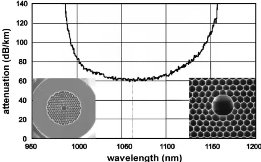
Fig I.11 : Attenuation spectrum of a hollow-core PCF designed for low-loss transmission of 1064 nm light. [10]
2. High harmonic generation: Hollow core PCF is likely to have a major impact
in other areas of nonlinear optics, such as x-ray generation in noble gases pumped by fs Ti:sapphire laser pulses. The conversion efficiency of this process could be further enhanced by modulating the bore diameter of the core so as to phase match the light and the x-rays (this was recently demonstrated in simple glass capillaries). In a hollow core PCF this could be implemented for example by heat treatment with carbon dioxide laser light. [10]
I.6.7 Telecommunications
There are many potential applications of PCFs or PCF based devices in telecommunications, although whether these will be adopted remains an open question. One application that seems quite close to being implemented is the use of solid-core PCF or “hole-assisted” SMF for Fiber To The Home (FTTH), where the lower bend loss is the attractive additional advantage offered by the holey structure.
Other possibilities include dispersion-compensating fiber and hollow core PCF for long haul transmission. Additional opportunities exist in producing bright sources of correlated photon pairs for quantum cryptography, parametric amplifiers with improved characteristics, highly nonlinear fiber for all optical switching and amplification, acetylene filled hollow core PCF for frequency stabilization at 1550 nm, and the use of sliced SC spectra as WDM channels. There are also many possibilities for ultra-stable in line devices based on permanent morphological changes in the local holey structure induced by heating, collapse, stretching, or inflation. [10]
1. New telecommunications window: Hollow core PCF is radically different
from solid core SMF in many ways. This makes it difficult to predict whether it could be successfully used in long haul telecommunications as a realistic competitor for SMF-28. The much lower Kerr nonlinearities mean that WDM channels can be much more tightly packed without nonlinear crosstalk, and the higher power handling characteristics mean that more overall power can be transmitted. The effective absence of bend losses is also a significant advantage, particularly for short-haul applications. [10]
2. Dispersion compensation: The large glass air refractive index difference
makes it possible to design and fabricate PCFs with high levels of GVD. A PCF version of the classical W-profile dispersion compensating fiber was recently reported, offering slope matched dispersion compensation for SMF-28 fiber at least over the entire C-band (Fig. I.12).
Chapter I Introduction to photonic crystal fibers
Dispersion values of −1200 ps/nm.km imply that only 1 km of fiber is needed to compensate for 80 km of SMF-28. The fiber was made deliberately birefringent to allow control of polarization mode dispersion.
Fig I.12 : Performance of a PCF designed to provide slope-matched dispersion compensation for Corning SMF-28 over the C-band.[10]
I.6.8 laser tweezers in hollow core PCF
A focused light beam produces both a longitudinal (accelerating) and a transverse (trapping) force on dielectric micro particles. For maximum trapping force, the intensity gradient of the light must be as high as possible. This can be achieved by focusing a high power laser beam with a high numerical aperture lens. The Rayleigh length for such a tightly focused beam is rather short; furthermore, the high intensity will quickly accelerate the particle out of the trapping zone. Stable trapping of a particle in free space requires the longitudinal force to be balanced either by gravity or by a second (or reflected) beam. [10]
I.6.9 Optical sensors
Sensing is thus far a relatively unexplored area for PCFs, although the opportunities are myriad, spanning many fields including environmental monitoring, biomedical sensing, and structural monitoring .Multicore PCF has been used in bend and shape sensing and Doppler difference velocimetry , double clad PCF in multi photon fluorescence measurements in medicine , and solid core PCF for hydrostatic pressure sensing .[10]
I.7
Conclusion
At the moment, it can be expected that PCFs for higher power next generation fiber lasers and amplifiers and for supercontinuum generation will be the first products to reach the “real” market that is to gain commercial opportunities also outside the academic world. In fact, even if PCFs were originally envisioned as a solution for higher data rates in telecommunications, conventional optical fibers currently in use are so good that PCFs do not offer an obvious advantage right now.
References
[1] Anders Bjarklev, JesBroeng, Araceli Sanchez Bjarklev (auth.), “Photonic Crystal Fibers, Springer”
US (2003).
[2] Aurélie Bétourné, ’’Conception et Caractérisation de Nouvelles Fibres Optiques à Cristal Photonique
dites Hybrides et Applications à l‟Optique Non Linéaire ‟‟, PhD thesis, university Lille 1.
[3] Federica Poli, Annamaria Cucinotta, and Stefano Selleri“, Photonic crystal fibers: properties and
applications, Springer (2007)”.
[4] Birgit Stiller,”Brillouin scattering in photonic crystal fiber:from fundamentals to fiber optic sensors, ”PhD thesis, Université de Franche-Comté ,2011.
[5] R. Buczynski,”Photonic Crystal Fibers “, Proceedings of the XXXIII International School of Semiconducting Compounds, Jaszowiec 2004.
[6] Rim CHERIF, ’’Étude des Effets Non-Linéaires dans les Fibres à Cristaux Photoniques, PhD thesis, university of 7 Novembre à Carthage, 2009 ’’.
[7] James Morgan Stone, “PHOTONIC CRYSTAL FIBRES AND THEIR APPLICATIONS IN THE
NONLINEAR REGIME», PhD thesis, University of Bath, April 2009.
[8] Melle Benaissa Fatima, ’’Etude et Simulation des Ondes Electromagnétiques dans les guides d‟Ondes
à Cristaux Photoniques-Application aux Fibres Optiques „‟, Magister thesis university of
ABOU-BAKR BELKAÏD – TLEMCEN, 2013.
[9] Jason C.W. Corbett, “A brief introduction to photonic crystal fibers for astronomical
instrumentalists”, Elsevier B.V.2006.
[10] Philip St .J. Russell, “Photonic-Crystal Fibers, JOURNAL OF LIGHTWAVE TECHNOLOGY, VOL. 24, NO. 12, DECEMBER 2006 “.
Chapter II Optical properties of photonic crystal fiber
Chapter II
Optical properties of photonic
crystal fiber
II.1 Introduction
Photonic crystal fiber is a new different type of optical fiber , so they can be defined by a different characterization, in this chapter we will take a general look about his optical proprieties such as the endlessly single mode, effective area, birefringence, chromatic dispersion, and loss mechanisms witch contents intrinsic loss (absorption, scattering), confinement loss and bending loss. In the end, we will mention the different modeling methods for PCF and we interested about finite difference frequency domain (FDFD) method.
II.2 PCF optical properties
II.2.1 Endlessly single
mode property
The first solid core PCF (Fig I.2), which consisted of a triangular lattice of air holes with a diameter of about 300 nm and a hole to hole spacing of 2.3 μm, did not ever seem to become multi-mode in the experiments, even for short wavelengths. In fact, the guided mode always had a single strong central lobe filling the core.
Russell has explained that this particular endlessly single mode behavior can be understood by viewing the air hole lattice as a modal filter or “sieve” .Since light is evanescent in air, the air-holes act like strong barriers, so they are the “wire mesh” of the sieve. The field of the fundamental mode, which fits into the silica core with a single lobe of diameter between zeros slightly equal to , is the “grain of rice” which cannot escape through the wire mesh, being the silica gaps between the air holes belonging to the first ring around the core too narrow. On the contrary, the lobe dimensions for the higher-order modes are smaller, so they can slip between the gaps. When the ratio , that is the air filling fraction of the photonic crystal cladding, increases, successive higher order modes become trapped. A proper geometry design of the fiber cross section thus guarantees that only the fundamental mode is guided. More detailed studies of the properties of triangular PCFs have shown that this occurs for .
By exploiting this property, it is possible to design very large mode area fibers, which can be successfully employed for high power delivery, amplifiers, and lasers. Moreover, by doping the core in order to slightly reduce its refractive index, light guiding can be turned off completely at wavelengths shorter than a certain threshold value. [1]
Fig II.1: The above schematics show how light penetrates into the cladding air holes for different wavelengths. The wavelength of light increases from left to right. The effective or average index of the
Chapter II Optical properties of photonic crystal fiber
II.2.2 Chromatic dispersion
The effective refractive index of a confined mode in a fiber varies as a function of frequency . The individual speeds experienced by different frequencies are different given by . Consider an optical pulse envelope propagating with several frequencies travelling at different speeds. The pulse envelope will spread out as it propagates, as the slower frequencies lag behind the faster ones; this process is known as chromatic dispersion. [3]
Fig II.2: Chromatic dispersion in the optical fiber. [4]
To describe chromatic dispersion of a pulse propagating in an optical fiber, a Taylor expansion of is taken around the central frequency of the pulse, , to give
Where
(
)
(II.2)
The coefficients and are related to the refractive index and its derivatives through the relations:
(
)
(II.3)(
)
(II.4)Where
v
g is the group velocity and ng is the group index. It can easily be seenfrom II.3 that the group index can be readily obtained from the second term of II.1.
Throughout this thesis we will refer to and as functions of wavelength. The parameter varies as a function of through the relation
The coefficient determines how the individual frequencies in a pulse envelope disperse as it propagates. This is known as group velocity dispersion (GVD) and it is quantified by , which is generally given in units of ps2km-1.
Dispersion is also quantified by the dispersion parameter, , which has arisen for practical engineering use and has units of picoseconds of spreading per nanometre of bandwidth per kilometer travelled, ps nm-1km-1. The parameter is obtained from by
the relation
(II.6)
D generally used rather than and given in terms of rather than . Rewriting II.4 for D in terms of we obtain [3]: (II.7)
II.2.3 Effective mode area
The effective mode area (EMA) of fibers can be derived from the modal distribution of the fundamental fiber mode and writes as
(∬ | | ) ∬ | |
(II.8)
Where is the transverse distribution of the optical mode, for SMF the fundamental mode. The EMA of a fiber is important because nonlinear effects are rising with higher intensity density. Since PCFs often have small fiber cores, their EMA is small as well and nonlinear effects get more important. The other way around, large mode area fibers are especially made to avoid high nonlinear effects such as Brillouin and Raman Scattering. Later we will see that the EMA plays a role for the critical power for stimulated Brillouin scattering. [5]
Chapter II Optical properties of photonic crystal fiber
II.2.4 Birefringence
The so called single mode fibers guide actually two optical modes simultaneously. They are orthogonally polarized and the two will propagate with the same velocity in perfectly radial symmetric fibers. In birefringent fibers, fibers that are not completely radial symmetric, these two modes have a different phase and group velocity because the refractive index is different for the different modes, propagating according to an x-axis and orthogonal y-axis. The phase modal birefringence is given by:
| | | | (II.9) With the mode propagation constant, the wave vector in vacuum and the
refractive index according to the axis. The group modal birefringence can then be written as:
(II.10) Conventional fibers are the oretically not birefringent but material and geometrical in homogeneities can induce a low birefringence in the order of 10−6. As one may think
that PCFs with a hexagonal structure may be birefringent since they have not the same air material distribution in x- and y-axis, it should be emphasized here, that this is not the case. The hexagonal symmetry of a perfect micro structured fiber leads to no, birefringence. Nevertheless, PCFs are more sensitive to irregularities, since small variations of the hole diameter lead to a different refractive index. Besides the drawing process of PCFs is more complicated and induces more fiber irregularities. On the other hand PCFs with asymmetrical air hole structure like two big air holes can reach ultra-high birefringence up to 10−2. [5]
II.2.5 Losses mechanisms
II.2.5.1 Intrinsic loss
The optical loss ,measured in dB/km, of PCFs with a sufficiently reduced
confinement loss can be expressed as:
Being , and the Rayleigh scattering coefficient, the imperfection loss, and
and infrared absorption losses, respectively. At the present time the losses in PCFs are dominated by -absorption loss and imperfection loss.
In a typical PCF the absorption loss is more than 10 dB/km at 1380nm and this causes an additional optical loss of 0.1 dB/ km in the wavelength range around 1550 nm. Since this contribution is very similar to the intrinsic optical loss of 0.14 dB/km for pure silica glass at this wavelength, the OH-absorption loss reduction becomes an important and challenging problem.
Most of the OH impurities seem to penetrate the PCF core region during the fabrication process. As a consequence, a dehydration process is useful in reducing the
OH- absorption loss.
Imperfection loss, caused mainly by air hole surface roughness, is another serious problem. In fact, during the fabrication process, the air hole surfaces can be affected by small scratches and contamination. If this surface roughness is comparable with the considered wavelength, it can significantly increase the scattering loss. Thus, it is necessary to improve the polishing and etching process, in order to reduce the optical loss caused by this roughness. Moreover, fluctuation in the fiber diameter during the fiber drawing process can cause an additional imperfection loss, if the air-hole size and pitch change along the fiber.
It is important to underline that the Rayleigh scattering coefficient of PCFs is the same as that of a conventional SMF. However, this is higher than that of a pure silica core fiber, although the PCF is made of pure silica glass. It is necessary to reduce the roughness further, in order to obtain a lower imperfection loss and a lower Rayleigh scattering coefficient. [1]
Chapter II Optical properties of photonic crystal fiber
II.2.5.2 Macro bending losses
The macro bending losses of optical fibers are very important to address, not only from a practical handling point of view, but also because they play a central role, when defining the spectral window, in which the fiber may be operated. The bending properties of PCFs were described by the introduction of a critical bend radius, a radius under which a PCF may not be bending in order for the excess bending loss to be below a given limit. The power loss coefficient due to macro bending is written as:
√
√
(II.12)
Where is the relative index difference between the maximum refractive index in the core region and the cladding index is the core radius, is the normalized frequency, and is the normalized decay parameter in the cladding. de notes the radius of curvature, is the amplitude coefficient of the cladding electric field, and is
the propagation power carried by the fundamental mode. Applying equation (II.12), the bend loss is directly calculated from the Bessel function coefficients and propagation constant of the effective index fiber. [7]
Fig II.4: Illustration of the optic tunnel effect in the standard fiber bending. The blue point inthe cut off effective’s index of fixλrecommend effective index equalitybetweenthe core modeand the cladding
![Fig I.1 : Examples for photonic crystals with 1, 2 and 3 dimensions. The different colors represent the materials with different index refractive.[2]](https://thumb-eu.123doks.com/thumbv2/123doknet/8186126.274851/18.892.184.759.341.527/examples-photonic-dimensions-different-represent-materials-different-refractive.webp)
![Fig I.3 : Cross-section of a PCF with hexagonal structure.[8]](https://thumb-eu.123doks.com/thumbv2/123doknet/8186126.274851/20.892.273.708.87.372/fig-i-cross-section-pcf-hexagonal-structure.webp)


![Fig I.8 : Classification of PCF according to their guiding mechanisms . [6]](https://thumb-eu.123doks.com/thumbv2/123doknet/8186126.274851/24.892.84.815.657.1128/fig-i-classification-pcf-according-guiding-mechanisms.webp)


![Fig I.12 : Performance of a PCF designed to provide slope-matched dispersion compensation for Corning SMF-28 over the C-band.[10]](https://thumb-eu.123doks.com/thumbv2/123doknet/8186126.274851/32.892.169.767.220.577/performance-designed-provide-slope-matched-dispersion-compensation-corning.webp)

