HAL Id: hal-01603010
https://hal.archives-ouvertes.fr/hal-01603010
Submitted on 2 Oct 2017
HAL is a multi-disciplinary open access
archive for the deposit and dissemination of
sci-entific research documents, whether they are
pub-lished or not. The documents may come from
teaching and research institutions in France or
abroad, or from public or private research centers.
L’archive ouverte pluridisciplinaire HAL, est
destinée au dépôt et à la diffusion de documents
scientifiques de niveau recherche, publiés ou non,
émanant des établissements d’enseignement et de
recherche français ou étrangers, des laboratoires
publics ou privés.
Dual field combination for unmanned video surveillance
Louise Sarrabezolles, Antoine Manzanera, Nicolas Hueber, Maxime Perrot,
Pierre Raymond
To cite this version:
Louise Sarrabezolles, Antoine Manzanera, Nicolas Hueber, Maxime Perrot, Pierre Raymond. Dual
field combination for unmanned video surveillance. SPIE Defense and Commercial Sensing, Apr 2017,
Anaheim, United States. �10.1117/12.2262696�. �hal-01603010�
Dual field combination for unmanned video surveillance
Louise Sarrabezolles
a,b, Antoine Manzanera
b, Nicolas Hueber
a, Maxime Perrot
a, and Pierre
Raymond
aa
Institut Franco-Allemand de Saint-Louis, 5 rue du General Cassagnou, Saint-Louis, France
bENSTA ParisTech U2IS/Robotic & Vision, 828 bd des Mar´
echaux, Palaiseau, France
ABSTRACT
Unmanned systems used for threat detection and identification are still not efficient enough for monitoring autonomously the battlefield. The limitation on size and energy makes those systems unable to use most state-of-the-art computer vision algorithms for recognition. The bio-inspired approach based on the humans peripheral and foveal visions has been reported as a way to combine recognition performance and computational efficiency. As a low resolution camera observes a large zone and detects significant changes, a second camera focuses on each event and provides a high resolution image of it. While such biomimetic existing approaches usually separate the two vision modes according to their functionality (e.g. detection, recognition) and to their basic primitives (i.e. features, algorithms), our approach uses common structures and features for both peripheral and foveal cameras, thereby decreasing the computational load with respect to the previous approaches.
The proposed approach is demonstrated using simulated data. The outcome proves particularly attractive for real time embedded systems, as the primitives (features and classifier) have already proven good performances in low power embedded systems. This first result reveals the high potential of dual views fusion technique in the context of long duration unmanned video surveillance systems. It also encourages us to go further into miming the mechanisms of the human eye. In particular, it is expected that adding a retro-action of the fovea towards the peripheral vision will further enhance the quality and efficiency of the detection process.
Keywords: Computer vision, Embedded systems, Biologically inspired, Peripheral/Foveal vision, Recognition.
1. INTRODUCTION
The interest in Computer Vision has recently gained importance, specially due to the last ten years progresses in imaging and computing technologies like the high quality, low power and cheap cameras, the high resolu-tion image sensors, the high speed processors and parallel processing architectures. All those revoluresolu-tions have brought more precise and higher quality input image information and allowed very fast computation. They have made possible to use algorithms that were computationally too expensive and limited by costly and cum-bersome hardware, cameras and frame grabbers. The increase in precision and quality of the sensor as well as the acceleration of the computation permit the development of new detection and recognition algorithms with really good performance and thereby open new horizon for artificial intelligence. However, the exponen-tial performance and complexity improvements as well as the lower energy and financial costs of the hardware systems, that was described by the law of Moore, has now reached its limits [1]. And in the current state, the most promising computer vision algorithms are still using too much computational resources and energy to be usable in an unmanned system. In applications of Defense and Security as well as in industrial applications of autonomous monitoring and surveillance, unmanned systems are developed under several strong constraints. In fact, they need to be easily carried and sometimes hidden, they need to have a long autonomy while keeping a continuous attention on every event happening in their zone of surveillance. That implies a minimization of the size, the weight, the computing resources and the energy consumption. Often the existing surveillance systems limit their functions to detection or even only to video transmission, letting the receiver computer or even the human operator performing the recognition process. But with the growth of information quantity coming from
Further author information: (Send correspondence to L.S.)
the high quality cameras and also from complementary multi-modal sensors, the bandwidth for their transmis-sion becomes quickly saturated. To reduce this amount of information it is important to place the recognition process in the unmanned system, thereby reducing them to only interesting events. Our research project aims to conceive, validate and optimize an architecture model improving the detection and recognition processes for unmanned video surveillance systems. The system should be minimized in size, weight and energy consumption, while performing real-time generic surveillance activities like detection, recognition and identification of events of interest such as unauthorized/authorized locations, actions, behaviors, situations of danger, involving differ-ent types of objects like humans, animals, cars, drones, etc. As usual in Computer Vision, the bio-inspiration seems to be a good guide for such problematics. Here in particular, the human visual system helps us in the construction of our model.
In this paper we propose a model and make an evaluation of its first developments. In Sec.2, we describe the elements in the human visual system that inspired us for the model, we show how to go further in the biomimicry of this system compared to other academic models already presented, and we have a look on which computing system could be the most appropriate for the implementation and validation of such system. Then in Sec.3 the functioning of this model is presented. In Sec.4, we present the new results obtained with the first implementation of the model and we estimate its expected computational performance. Finally in Sec.5, we explain why this model seems promising and which further developments are planned.
2. RELATED WORK
In order to design a model for unmanned video surveillance systems, it seems interesting to have a look on the natural systems. Indeed, the biological systems are a good source of inspiration in many computation fields (e.g. swarm intelligence, evolutionary computing, artificial neural networks, artificial immune systems [2]), because of their variety, their adaptability, and their sophistication still unequaled by the human made systems. In this paragraph, we have an overview on the biological vision systems and their biomimetic to establish which trends should be taken for the model design. In fact, the biomimetics of natural vision systems can bring a level of genericity and help to optimize architectures for unmanned systems. However the limitation in the current electronic and computing resources is a restraint in the biomimetic possibilities. Consequently, a study of the available computing resources is also necessary to establish our model.
2.1 Biological human vision
Recently new interests in biological visual systems and other sensor systems have arisen and have helped in the development of new methods. Among those approaches the human vision is the most investigated. The recent advances in neurosciences show several key points of its process that can be exploited by future bio-inspired vision systems. Since the works of Hermann von Helmoltz at the end of 19th century showing that the eyes
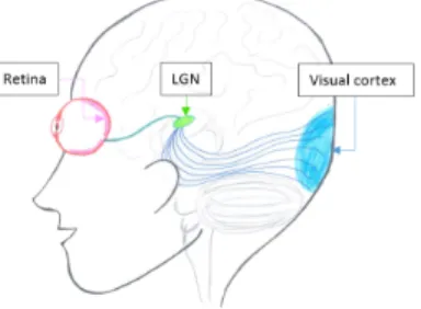
only couldn’t make the vision possible [3], psychophysicists, neurophyicists and physiologists have continued to improve the knowledge on the primate vision. Schematically, the human visual system is composed of three pro-cessing parts: the retina, the lateral geniculate nucleus (LGN) and the visual cortex (Fig.1). A recent description of it can be found in [4] for more details.
Figure 1: Representative schema of the human visual system. The retina, the LGN and the visual cortex belongs to three different parts of the skull.
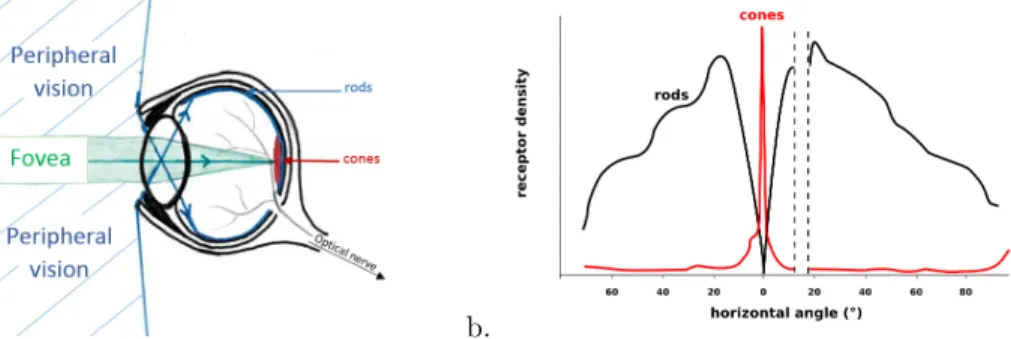
The retina is the first part of the system. It captures the photons from the observed scene and performs the first cellular processes on the image. The photons are perceived by two types of photo-receptors: the rods, sensitive to the light intensity, and the cones, sensitive to the photon’s wavelength (i.e. its color). There are three kinds of cones: one sensitive to the red wavelength, one to the green one and the last to the blue one. Those two types of receptors are not evenly distributed on the retina, the cones are concentrated in the center part of the retina, called fovea, and the rods are mostly absent from the fovea and more concentrated in the periphery of the retina. This repartition reflects the actual two vision fields used by humans: the peripheral vision, which consists in being attentive to any change within a low resolution peripheral view, and the foveal vision, which consists in focusing on something particular in the scene in order to interpret it (Fig.2).
a. b.
Figure 2: Repartition of the cone and rod cells on the retina. a. Representative schema of the two visual fields. b. Density repartition of the receptors depending on the angle view. There is a ”blind spot” in this repartition corresponding to the optical nerve.
The signal perceived by cones and rods is processed in the retina by complex cells, providing to the signal trans-mitted to the brain a higher level spatio-temporal structure, related to motion, direction or contrast information. The retina of the two eyes are linked to the LGN by the optical nerve. The LGN is composed of six layers of neurons. Those layers receive and process separately the different kinds of signals sent by the eyes. There, a first stereoscopic matching is done as well as a higher level of processing. The feed-forward, feedback and transversal neural connections present in the LGN permit: to send the visual information to another part of the brain, the visual cortex; to match information coming from the two eyes; and also to control them, their position, their focus, etc. Finally the last processing part, and the most complex one, is the visual cortex. It is decomposed into different layers: V1, V2, etc. Some seem to process information linked to the ’where’ (MT), others to the ’what’ (IT) (Fig.3). It is often represented as a feed-forward processing model in which the signals are processed successively by the layers. Each layer would bring a higher level of description of the observed scene.
Figure 3: Simplified schema of the right hemisphere visual cortex of a primate. It shows the two parallel visual processing streams: ”what” and ”where”. (Schema from the article of James A. Bourne [5]).
This classical visual cortex model is however controversial, as feedback and transversal neural connections exist between all those layers and the LGN. A more consistent model should try to combine in a more intimate way the different visual processes of the brain which are enabled by those neural connections.
2.2 Human vision biomimetics
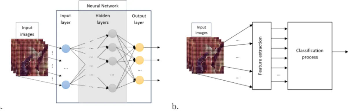
As the knowledge on the human visual system was growing, the adapted models for smart recognition changed. Today, there are two models that are mostly used by the computer vision community (Fig.4).
On the one hand, the full-neural model simulates the whole visual process by a neural network taking as an input the RGB matrix and giving as an output the class of an object or a scene (deep neural networks are such examples). On the other hand, the feed-forward model pre-processes the RGB matrix with feature extractors in order to have more relevant information before classification process (e.g. neural network, support vector machine or random forest). The first model has recently presented a lot of interesting results, however it needs very large computing capacities and a large dataset to be configured. Even if many researches aim to adapt it to long autonomy unmanned systems, embedded deep networks are not fully available yet or even proved to be as performant on embedded systems as they are on powerful workstations. The best performing version of the second model shows the same difficulties as the first one, since they often use very complex features and high-power learning systems. However, the sub-optimal versions of this model, using low-power learning systems and simple features, could be improved if they are getting closer to the biological model.
a. b.
Figure 4: The two most used models: a. The full-neural model learns the classification function directly from input images. b. The feed-forward model uses a feature extraction step to reduce the complexity of the following classification process.
There already exists some hardware sensor combinations that are closer to the biological system than the current use of a single camera using a CMOS or CCD sensor. In fact there is the possibility to recreate the stereo-vision with two cameras, the dual field of views (peripheral/foveal) with two cameras and even the asynchronous transmission of the visual information. Indeed, some recently developed cameras called spike cameras are event-driven like the retina (whereas the CMOS/CCD cameras are time-event-driven). But their formalism for application as well as their implementation within complete systems don’t seem mature enough today for an autonomous surveillance system. The stereo-vision brings more spatial information to the system, making it more precise, but it generates complex reconstruction algorithms increasing the need in size, weight and energy. The gain of the stereovision for feed-forward model are bellow our expectations specially when compare to the dual field view that drastically reduces the quantity of processed information. Indeed, the peripheral view camera can have a low resolution as the high resolution camera is used in the foveal field only when something is detected. Several researchers already tested this dual field vision for autonomous surveillance. Hengster et al.[6] and Xu and Song [7] realized a complete system where the information from the peripheral camera guides the position of the foveal camera. They were able to make it run in real-time. Horaud et al.[8], like Huang et al. [9] went further by using the information of the foveal camera for improving tracking capabilities, doing so they showed a real-time cooperation possibility. They showed by their implementation the reproducibility of one of the feedback actions between the brain and the eyes: the control of the position and the focus of the eyes.
Recently Medathati et al.[10] drew attention to the importance of those retroactions and even more of the interactions between the different computation layers in the vision process and encouraged the computer vision community to develop a new computational model of the human vision that would take them into account.
2.3 Hardware advances and limits
Since the era of ubiquitous parallel processing, there exist a large number of different hardware devices that can be used to implement more and more sophisticated biomimetic models. From a computational point of view, indeed, the human visual system is intrinsically parallel and heterogeneous.
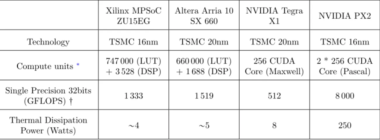
However, these devices do not have the same flexibility and the same computational costs, in terms of time and energy. The digital signal processors (DSP) can execute specialized instructions. The graphic processor unit (GPU), specially the most recent ones, are also very flexible and programmable, but they consume a lot of energy. It is the same for the Intel Xeon Phi processors, which are easily programmable, but not size, weight and power (SWaP) optimized. The Heterogeneous data processing on FPGA or System on Chip (SoC) provides many libraries of configurable logic blocks enabling parallel processing within a parallel structure. Moreover, a parallel processing on such optimized structures is performed with a lower clock frequency, reducing the overall energy requirements. A comparison of the most recent systems shows that the FPGAs and SoCs are best adapted to an embedded application miming the visual human system (Tab.1).
Table 1: SoC Performances table
Xilinx MPSoC ZU15EG Altera Arria 10 SX 660 NVIDIA Tegra X1 NVIDIA PX2 Technology TSMC 16nm TSMC 20nm TSMC 20nm TSMC 16nm
Compute units ∗ 747 000 (LUT) + 3 528 (DSP) 660 000 (LUT) + 1 688 (DSP) 256 CUDA Core (Maxwell) 2 * 256 CUDA Core (Pascal) Single Precision 32bits
(GFLOPS) : 1 333 1 519 512 8 000 Thermal Dissipation
Power (Watts) „4 „5 8 250
The FPGA proved to be a good choice for embedded application, as the European Laboratory for Sensory Intelli-gence was able to develop efficient and low consumption neural networks [11]. At the same time, companies such as Qualcomm and Movidius developed vision processors based on the feed-forward and the full-neural models. But their low-power processors have not proved yet to be adapted to long autonomy detection and recognition applications.
During our research on existing bio-inspired visual processing systems, a processor developed by BVS-Tech [12] drew our attention. Its development began thirty years ago with the first implementation [13] made by its inventor P. Pirim. Since then, it went up following a bio-inspired approach using the last technological and biological discoveries. The chip mime the vision functions described by Hubel and Wiesel [14] and it follows the principle of cortex plasticity demonstrated by Bach-y-Rita [15]. The system also mimes the ”dynamic attractor” studied by Renn´o-Costa et al. [16], which permits the convergence to the combined information of the ”what” and ”where” streams. Its implementation is done with a unique process scanning all pixels at high frequency. Then, the connections of this system, compared to full-neural networks, are drastically reduced and thus its processing time too. The processor has been used in different use-cases (detection, traking and recognition [17] [18]), this diversity shows a certain flexibility of the system, which is low-power (3W). The combination of these
∗
For the FPGA it represents the Logical Unit Table (LUT) and the Digital Signal Processing block (DSP). For the NVIDIA GPU, the Core CUDA is based on the Maxwell and Pascal architecture, each unit is composed of SMM (Streaming Multiprocessor). One SMM (Maxwell) includes 4 32-way SIMD.
: FLOPS : Floating Point Operation Per Second, the operation can be an addition or a multiplication, this metric represents the theoretical performance.
properties widen the application range. However there is still no formalization of the system permitting its inte-gration in a complete visual system. This formalization will help the understanding and therefore the inteinte-gration in our processing model, while keeping its interesting computational performances.
Biomimetic models in Computer Vision are limited by the processor capabilities and its need in energy that often goes beyond the embedded application limits. The SWaP constraints of an unmanned video surveillance system impose to choose electronic implementation device such as FPGA or SoC, which are low power. As those hardware devices are limited in computational power, it is also essential that the algorithms minimize their computational needs. Moreover, the recent biological studies urge Computer Vision researchers on re-newing their models for more accurate ones. In fact, the use of pre-processing like those made in the retina, the LGN and the cortex layers and the use of all direction connections between processing parts would bring a higher level of understanding while reducing the information quantity. Thus, it would enable a reduction in the computational costs when implementing the model. The interesting processor developed by BVS-Tech is able to extract spatio-temporal features, detect and recognize objects in a biologically inspired way with very low computational requirements. The adaptation of this processor for a dual vision field system could enable the combination of information from the two views and thus the construction of a more biologically plausible model, able to outperform the existing models for unmanned video surveillance.
3. OUR APPROACH
The study of the biological human vision system and the study of the different image analysis computing systems made in Sec.2 provided us with trends for improvement that could benefit to unmanned surveillance systems. Our approach is based on the dual field of view model using the classical feed-forward computer vision model for recognition. We propose to improve this model by combining information from the two visions in a bio-inspired processing adapted from the BVS-Tech technology. Firstly, a mathematical formalization of the BVS-Tech chip processing is proposed in order to describe how the chip works and then how to use it in the proposed model. Secondly, the detailed description of the model integrating this processing on the two combined vision information is presented.
3.1 Mathematical formalization
The chip developed by the BVS-Tech company is composed of three levels of processing [17]: the feature extrac-tion, the objects’ detection and description and the classification made by an associative memory. The feature extraction level is composed of local computation of the following features: luminance, hue, saturation, gradient module and angle, curvature, velocity module and direction. Those local features correspond to some processing made in the retina, the LGN and the first cortex layers. The objects’ detector and descriptor converge to the objects parts in the image, giving their position and their feature description. Then, the classification level uses an associative memory. (Fig.5).
Figure 5: Schema representative of the BVS-Tech chip processes: the feature extraction (in green the temporal features and in red the spatial features), the detector and descriptor processing, which gives a set of sub-object description and position Vk, the classification processing.
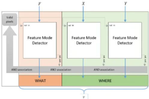
The originality of the processor mostly lies in the detector and descriptor module. Its construction is generic and independent from the input features. In fact, in the same way as the human brain plasticity, its internal processes could be used on visual, acoustic and tactile features alike. The object’s detector and descriptor is a combination of multiple ”bio-inspired perception sensors” (BIPS). Each of them converge to a local maximum of energy combining the temporal and spatial informations. This process corresponds to a ”dynamic attractor” (DA), which does the correspondence between the ”what” and ”where” processing parts within the visual cortex. The BIPS module is constructed as a combination of three sub-modules attached to one temporal feature or one of the two spatial features : X or Y. Each sub-module converges dynamically to the maximum of the marginal histogram corresponding to the feature it is attached to. These ”feature mode detectors” (FMDs), are linked by AND connections and dynamically update their pixel validation criteria, which permit the convergence to a local maximum of energy in the three dimensional feature space (Fig.6).
Figure 6: Representative schema of the BIPS module, which is composed of three ”feature mode detectors” (FMDs) linked by the bus of pixel validation. The FMD processing the temporal feature F gives information about the ”what” and the FMDs processing the spatial features X and Y give information about the ”where”. The output of the three FMDs correspond to a sub-object description and position V .
Figure 7: Representative schema of an extended BIPS module, which is composed of several LMDs linked by the bus of pixel validation. Its output corresponds to a sub-object description and position V .
Currently the BIPS module is composed by only one temporal feature and the two spatial features. The com-bination of several modules BIPS by XOR and AND connections permits to obtain local maxima of energy of various temporal features. But, the structural description of the detector and descriptor can be simplified mathematically to combinations of FMDs. A set of those sub-modules linked by AND connections gives the description and position of a sub-object (Fig.7). Such extended BIPS modules still follows the principle of a DA but with more features. And their combination by XOR connections gives a set of sub-object positions and descriptions composing the input image. The mathematical description of the FMD sub-module, made in the following paragraph, permits to understand and adapt the complete module to specific needs.
The input of the module is a set of features Fn calculated by the feature extractor.
Fn: X ˆ Y ÝÑ Ωn
x, y ÝÑ f “ Fnpx, yq,
(1)
where X “ v0; Ww and Y “ v0; Hw are the pixel coordinate ranges of the input image. The feature extractor makes actually the transition from the input image to the multi-dimensional feature space Ω. It can be described by the function F :
F : X ˆ Y ÝÑ Ω “ Ω1ˆ . . . ˆ ΩK
x, y ÝÑ f “ F px, yq
ô pf1, . . . , fKq “ pF1px, yq, . . . , FKpx, yqq .
(2)
The feature extractor F of the BVS-Tech chip is described in the Tab.2.
Table 2: Feature extractor of the BVS-Tech chip. YCbCrptq is the input image.
Feature Definition Luminance Y Hue arctanˆ Cb Cr ˙ Saturation b C2r` C2b Estimated
background Yest αYptq ` p1 ´ αqYest
pt ´ 1q, where α “ 1 2Dt Temporal Constant Dt $ ’ ’ & ’ ’ %
Dtptq “ Dtpt ´ 1q ´ 1 if |Yptq ´ Yestpt ´ 1q| ą εDt and Dt ą 0
Dtptq “ Dtpt ´ 1q ` 1 if |Yptq ´ Yestpt ´ 1q| ď εDt and Dt ă Dtmax
VelocityÝÑV Apparent displacement vector, provided by optical flow estimation
Gradient ÝÑ∇Y
Curvature ´ 1 ||ÝÑ∇Y||.
B2Y
Bt2, where t is the unit isophote vector, perpendicular to the gradient
The function of a DA is to converge iteratively to a selection of pixels representative of a local maximum of energy in the feature space Ω. We call sub-object O such selection of pixels. At each iterative step k, the extended BIPS module process can be decomposed into two steps: the marginal histograms computation and the sub-object Ok
creation. Where the sequence pOkqk converges to O.
The marginal histogram Hk
n corresponding to the feature Fn is:
Hnk: Ωn ÝÑ N f ÝÑ q “ Hnkpf q, (3) where Hnkpf q “ card " p P X ˆ Y N Fnppq “ f, @m P v1; Kw, Fmppq P rAkm; Bmks * . (4)
Akmand Bmk are respectively the lower and upper bounds of the feature m and form the active domain Pk defined by: Pk “ K ź m“1 rAkm; B k ms. (5)
The sub-object corresponding to this active domain is: Ok “ F´1pPkq, ô Ok “ p P X ˆ Y L@m P v1; Kw, Akmď Fmppq ď Bmk ( , ô Ok “ Ş 1ďnďK F´1 m ` rAkm; Bmks˘ , ñ Hk npf q “ card tp P Ok{Fnppq “ f u (6)
At the initialization step, O0“ Ω and @m P v1; Kw, B0m(respectively A0m) is equal to the maximum (respectively
the minimum) of Ωm. Then at each iterative step k, the bounds of the feature n are updated, where n is such
that D p P N { k “ pK ` n.
The computation of the marginal histogram gives the following information, that corresponds to the output of the nth FMD. Nk “ card pOkq “ ř f PΩn Hk npf q, @n P v1; Kw Mk n “ max f PΩn `Hk npf q ˘ Vk n “ arg max f PΩn `Hk npf q ˘ (7)
where Nk is the number of selected pixels, Mnk is the maximum of the marginal histogram n and Vnk is one of
the value corresponding to the maximum.
The update of the bounds Akn and Bnk plays an important role for the convergence of the DA to the right
sub-object O. There are two different kinds of update, depending on what kind of sub-object we are looking for: one concentrates around a unique maximum (mode 1), the other includes all significant maxima (mode 2) (Fig.8). The two modes are described below:
Mode 1 : Ak`1 n “ inf ! f P Ωn M @f1 P rf ; Vnks, Hnkpf 1 q ą τn,k ) , Bk`1 n “ sup ! f P Ωn M @f1P rVnk; f s, Hnkpf 1 q ą τn,k ) , (8) Mode 2 : Ak`1 n “ sup ! f P Ωn M @f1P rminpΩnq; f s, Hnkpf 1 q ă τn,k ) , Bk`1 n “ inf ! f P Ωn M @f1 P rf ; maxpΩnqs, Hnkpf 1 q ă τn,k ) , (9) where τn,k ă Mnk.
Figure 8: Example of the marginal histogram corresponding to the gradient angle feature computed from a car image at the first iteration. The outputs of the FMD are represented for both modes.
The sequence pPkqk of active domains is a decreasing sequence that can never be empty. Consequently, it
converges in a finite time to a domain P depending on the choice of all τn,k. And the sequence of corresponding
pOkqk converges to the sub-object O:
D klimP N, Oklim“ lim
kÝÑ8Ok “ O, ñ $ ’ ’ ’ ’ & ’ ’ ’ ’ % @ k ě klim, Akm“ lim lÝÑ8A l m“ Am, Bk m“ lim lÝÑ8B l m“ Bm, O “ Ş 1ďmďK F´1 m prAm; Bmsq . (10)
In the BVS-Tech chip, τn,k “
Mk n
2 .
In case of noisy images the DA can converge on a small group of noisy pixels. To reject those ”false detections”, the system is also configured to stop the convergence if the number of selected pixels Nk is inferior to a threshold.
Then all the FMDs of the extended BIPS module are reinitialized until another sub-object comes into the video frame. This module permits to find one sub-object in the image. To find several sub-objects, the liaison XOR must be added between different modules. In most of cases, the XOR liaisons aim to split the feature space and let each DA converge in difference parts of the space. Moreover, the system is dynamic. It is adapted to video inputs and the incrementation of its convergence correspond to the incrementation of video frames. In order to adapt the convergence to moving sub-objects, a prediction ∆k
nis added when computing the new limits Ak`1n and Bnk`1.
The study of the BVS-Tech system and the mathematical formalization of its ’detector and descriptor’ module demonstrate how this latter converge to local maxima of energy of the feature space and which parameters influence this convergence. This mathematical understanding is the first step towards the definition of a global vision system able to classify relevant objects.
3.2 Field combination model
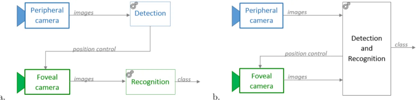
The study of the possible biomimetic made in Sec.2.2 gave us three principal trends that would improve the dual field feed-forward recognition model. Firstly, we can go further in the dual vision biomimicry best suited to unmanned video systems. In fact, as explained in Sec.2.2, most researchers associate the peripheral vision to
the detection and control processes and the foveal vision to the recognition process only. But the biology of the brain does not make such separation, both signals coming from the fovea and the periphery of the retina are processed by similar cells and brain circuits. It can then be supposed that both information from the fovea and the periphery are useful to the detection and the recognition processes. Therefore, the proposed model does not have such separation (Fig.9).
a. b.
Figure 9: a. The classical model used in dual field systems: the peripheral vision is used for the detection and control function, the foveal vision is used for recognition. b. The advanced model, closer to the biological system.
Secondly, the use of generic and bio-inspired feature extractor, detector and descriptor like the one used in the BVS-Tech chip could permit an improvement of the recognition performance while keeping the size, weight, power consumption minimal. Such system can be adapted to the foveal images, the peripheral images, as well as the combination of the two and provides a reduced and higher level information on the relevant elements of the scene. Thirdly, the feed-forward model, composed by such module and a classification process, could be enhanced by adding feedback and transversal connections like those present in the brain. The exact reproduction of those connections is not currently possible as they are not yet all completely understood and it is consequently rather hard to reproduce the same behavior at the electronic level. But the model architecture can take into account the existence of such feedback and internal exchanges and have some connections of the same kind: the retro-action for the foveal camera control can use the attention information coming from the analyze of the peripheral view and the tracking information coming from the foveal view. Also, connections between the different internal modules of the system will permit a dynamical adaptation of the feature extractors and the ’detector and descriptor’ parameters (Fig.10). Thus, the context and the objects described by the analyze of both peripheral and foveal views can influence the internal mechanisms by changing: the features to extract, the input set of features for each sub-module, the convergence mode or its parameters.
In this model the processing steps can be described in three principal modules as follows.
Firstly the images from the peripheral view and the foveal view are transformed into a feature space. The chosen features can be simple or complex, representative of local, regional or global characteristics, but they should respect the constraints of an autonomous visual system and they should discriminate different classes of objects. Secondly, the extracted features are sent to extended BIPS modules as defined in Sec.3.1. Each module is com-posed of several ”feature mode detectors” (FMDs) that are linked by AND connections and provide respectively an output vector Vn which permits the description of the sub-object the module is converging to. Each vector
contains information on the number of pixels Nk, the maximum Mnk and its associated values: the histogram
value Vnk, the prediction ∆kn, the threshold τnk and the bounds Akn and Bnk. The combination of these vectors provides information on the position, the feature description and the degree of confidence of the sub-object. Thirdly, the outputs from all the extended BIPS modules form a vector describing the different sub-objects of the scene (Fig.11). Then, this vector can be used for the classification process.
Figure 10: Model of detection and recognition processes combining both peripheral and foveal informations, integrating the descriptor and detector module adapted from the BVS-Tech technology and using different kinds of connections between the processes to enhance the performances.
Figure 11: Combination of FMDs forming a detector and descriptor module. It is composed by several DAs j converging to different sub-objects. Their inputs are made by selections of features from the feature input set pFiqiand their outputs pVjqj by the combined outputs of each FMD. Each Vj is a representation of a sub-object
and the final vector V is the representation of the scene.
Our approach is based on bio-inspired processes that can enhance the recognition performances in an unmanned video surveillance system: the dual field vision view, the features extraction, the combination of those informa-tion in a generic detector and descriptor and finally the classificainforma-tion. But we also based our approach on existing hardware equipments, that shows the possibility of respecting SWaP constraints and specifications for embedded optronics equipment. The dual field of view has already been used in different cases cited in Sec.2.2, three real-time classification processes implemented on a FPGA [11] and the system on-chip developed by BVS-Tech shows some interesting results. As no mathematical formalization had ever been made on the BVS’s concept,
we studied and formalized it in order to adapt it to any recognition system architecture. This study shows that the originality of the system relies on a module reproducing some of the function of the biologic ”dynamic attractors”. This module is composed of several ”feature mode detectors”, that can be combined by AND and XOR connections to converge to a rich description of the scene. If those connections are fixed, the output of the module is a fixed size vector that can become the input of the following classification process.
4. METHOD AND FIRST EXPERIMENTAL RESULTS
The model proposed in Sec.3is firstly tested with a simulation on computer. The current state of the simulation allows to recreate the recognition performance of the BVS-Tech chip and to extend it to different combinations of FMDs. Evaluating the computational performance is also possible as we already know the computational cost of the B-SAVED and BVS-Tech chip.
4.1 System model simulation
The model is composed of several modules connected to each other (see Fig.10). In order to test this model and easily manipulate its modules and their parameters, we developed a simulator in C++. The current software simulator mainly reproduces the feature extractor and the FMD functions. It is easily configurable with different combination rules of FMDs and it has been graphically interfaced for direct result visualization and validation. Thus the connection rules i.e. AND and XOR, and the choice of FMDs can be fully customized to match the application requirements. Currently the feature extractors correspond to those performed in the BVS-Tech chip. However, other features can be added and used as input of the FMDs. For the moment, the classification part has not been yet added as the first experimentation was to analyze the results issued by the FMDs.
The implemented feature extractors correspond to the tonal, structural and dynamic features developed in the BVS-Tech chip. The output images of this first module are shown in the Figures12and13. In the Fig.12, they correspond to the luminance, the hue, the saturation and the gradient angle and module. In the Fig.13, they correspond to the temporal constant Dt and the velocity module and direction. Those tests have been realized on images and video available on the Matlab library.
Figure 12: Capture of the graphical user interface for the feature outputs visualization and configuration. The luminance, saturation, hue, gradient angle and module and the hue and angle valid pixels matrix are displayed in the window. The hue is computed only for pixels whose saturation is above thres sat: here fixed to 20. The gradient angle is computed only for pixels whose gradient module is above thres grad: here fixed to 20. The derivated Gaussian kernels used for the gradient computation are of size 7x7.
Figure 13: Capture of the graphical user interface with another set of features. The temporal constant Dt (Tab.2), the background estimation, the velocity module and direction, the optical flow corresponding and the dynamic valid pixels matrix are displayed in the window. The dynamic features are computed only for pixels whose difference between luminance and estimated background is above thres dt here fixed to 50. The Dt is incremented or decremented of dt unit: here equal to 1; and is between 0 and dt max: here equal to 8.
The behavior of the FMD and the combinations of FMDs have also been tested on simulated and real images. The simulated images permit to confirm the expected behaviors of the sub-module. The manual construction of the image permit to create images with the different scenarii for the convergence. We have been able to test the convergence with different feature spaces, where there is only one sub-object, then with several sub-objects in the condition of perfect and non perfect differentiability of the sub-objects. Then, we used real images to observe the behavior of the sub-module in real condition with noise and a multitude of sub-objects.
The Fig.14 shows the evolution from k “ 1 to k “ 4 of a basic combination of FMDs: one on the hue, one on X and one on Y (like the BIPS module). This example on a perfect green circle shows how each FMD converges to the maximum of the corresponding feature histogram and the evolution of the active domain Pk
and the sub-object Ok. We can observe the convergence obtained by alternating the update of each FMD. Here
the threshold is set to:
τn,k“
Mk n
2
In the Fig.15, we use another synthetic static image and show the results obtained with different τn,k. This
threshold has a strong influence on the convergence. When it is small compare to Mnk, the sub-object obtained is
larger, and can incorporate some noise around the true values of the sub-object features. At the opposite, when it is near Mk
n, the resulting sub-object corresponds only to a compact part of the real sub-object.
In the Fig.16, the XOR connection between different extended BIPS module has been tested. One converges to the red ball, while another converges to the background, a third one to the line of black dashes and the last one to the gray rectangle. The first set is focused on the hue, while the three other sets are focused on the luminance. At the first step, two FMDs receive a non empty set of valid pixels: the set of FMDs on the hue and the first set of FMDs on the luminance. The convergence of the DA 1 and the DA 2 are done at the step 4. The DAs 3 and 4 depend on the convergence of the precedent DAs of the same kind, consequently their convergence is obtained at step 5 for the DA 3 and at step 6 for the DA 4. This example shows the sequentiality needed for the XOR connections. The exact implication of those connections will be studied in future works. This example also shows the use of the mode 2 to detect the line of black dashes, whereas the mode 1 would have converged to only one of the black dashes.
k “ 1 k “ 2 k “ 3 k “ 4 Ok rAkX; BXks ˆ rAkY; BkYs Hk hue HXk Hk Y
Figure 14: Representation of three FMDs outputs on a simulated static image. The time is incremented from left to right. The first line shows the matrix of valid pixels, the second line the spatial bounds projected in the image, the third, fourth and fifth lines shows respectively the hue, X and Y histograms and their bounds.
τn,k“ Mk n 2 τn,k“ Mk n 4 τn,k“ Mk n 16
k “ 1 k “ 3
k “ 5 k “ 6
Figure 16: Spatial bounds obtained by four extended BIPS module linked by XOR connections. The first set is composed of one FMD for the hue, one for X and one for Y. The three other sets are composed of one FMD for the luminance, one for the X and one for the Y. The mode 2 is used for the spatial features convergence. The convergence of all sets is achieved in 6 steps.
In the Fig.17, another combinations of FMDs has been tested on a real image. The sets are all using one FMD for the gradient angle, one for X’ and one for Y’, where X’ and Y’ are the rotated space features. All use the mode 1 for the temporal feature and the mode 2 for the spatial feature.
The DA 1 converges to the horizon, the DA 2 converges to the right side of the yellow line, the DA 3 converges to the left side of the yellow line and the DA 4 converges to the left side of the road. This example illustrates several aspects of the system. Firstly, its capacity to adapt to the rotation. Secondly, the relevance of using the mode 2 to find sub-objects that can be occluded (e.g the horizon) or are very thin (e.g. road borders), which causes discontinuities within the sub-object. Thirdly, the importance of the choice of FMDs composition (e.g. here, the number of sets is not sufficient to entirely recover the road borders).
The first experiments confirm the expected behavior of the combination of FMDs. The convergence are ob-tained between four to seven steps depending on the number of XOR and AND connections. But it also reveals the importance of the feature and parameter choices. The threshold τn,k plays an important role in the
separa-tion of sub-objects and their delimitasepara-tion. The chosen modes, the order of the DAs and of the sub-modules also have an influence on the result.
k “ 1 k “ 3
k “ 5 k “ 7
Figure 17: Spatial bounds obtained by four extended BIPS modules linked by XOR connections. They are composed of one FMDs for the gradient angle, one for X’ and one for Y’. The mode 2 is used for the spatial feature convergences. At step 7, all the DA have converged.
4.2 Evaluation of performance
The proposed model is based on different existing hardwares, whose computational performance are known. This allows us to estimate the overall costs and performances of an implemented version of the model. The B-SAVED system [11], developed at the European Laboratory for Sensory Intelligence (ELSI) is a platform for research development, which could integrate the model proposed in this publication. Its hardware design, with three cameras for the peripheral view and one mobile camera for the foveal view, only requires 3W with its detection, classification and transmission units ON. The BVS-Tech chip [17], whose processes are to be used in the model, showed a consumption of 2, 1W when integrated in a complete visual system. An estimation of the model consumption, if it only combines the previous hardware, should be around 5.1W.
This promising estimation only confirms that the model would be adapted to SWaP constraints, but an es-timation must also be done on its computational time to demonstrate its capacity to work in real-time. It can be analyzed on the basis of the computational time required for each function in the BVS-Tech implementa-tion. The computation of each frame can be decomposed into the following steps: feature extraction, histogram computation (including computation of maximum and its argument), prediction and new histograms bounds Ak n
and Bk
n computation. Indeed, the modeled and simulated feature extraction modules, as well as the FMDs, can
evolve in parallel on FPGA. The four steps can be splited: the two formers are dependent on the number of pixels per frame and the two latters are dependent on the number of bins of the histogram.
The input data are analyzed pixel per pixel at clock rate, which is mandatory for the histogram constructions. For each pixel, the feature extractions used in the BVS-Tech chip and the update of the histogram have a neg-ligible computational time compared to the pixel clock time (highly parallelized structure with high frequency clock). These processes need at the most four operations. A dedicated clock rate (4ˆpixel clock) enables to avoid any extra delay. Consequently, the computational cost of the overall process is equal to the frame rate. The prediction ∆k
n and new bounds Akn and Bnk computation (Fig.8) are dynamically adjusted as the different
successive histogram bins are read. The two functions need to go through all the histogram values, which are defined by a fixed number of bins Nbin (in the BVS-Tech chip this number is 1024, as it works in 10 bits).
Concerning the prediction step, which is used for moving objects, it currently corresponds to the difference be-tween medians from the previous and the current steps. The computation of the median needs only one reading process for each histogram value. The computation of the new limits needs even less reading processes as it goes only from the maximum to the new bounds values (for the mode 1) or from the domain borders to the new bounds values (for the mode 2) (the two modes have been described in Fig.8). Consequently, the computational time for this group of functions corresponds to at most one time the number of bins of the histogram.
Table 3: Computational time performance
Function Time (pixel clock quantity) Feature extraction and Histogram computation ă W ˚ H
Prediction and new borders computation ă Nbin
Complete system ă pW ˚ Hq ` Nbin
The BVS-Tech chip uses the pixel clock range: 25-50MHz. In real-time (30fps), the system should be able to analyze 1, 5G pixels. For example, using a standard CMOS sensor Wide VGA (752 ˆ 480 pixels) and a pixel clock frequency of 27MHz and 10 bits for coding the features, the computation time for each frame would be less than 13 ms. In order to mitigate the computational cost and data transfer a dual vision mechanism with low resolution CMOS sensors is well suited for this new concept. The computation time then permits to work with a high frame rate and to obtain results at 30fps. Then, the object representation results require several frames to converge. The number of frames depends on the choice of features and the disposition of the FMDs as shown in Sec.3.1. The frame rate parameter is of major importance to maintain a real-time detection and recognition. In fact, the DA needs a number of frames superior to the number of FMDs it is composed of to converge. In the best case, one evaluation of all the chosen FMDs is enough for the system to converge. This best case is obtained when the sub-object is well separated from the other sub-objects in the chosen feature space. This implies a right choice of features and of the threshold τn,k.
This work demonstrated that the main software modules emulating the BVS-Tech technology are fulfilling the embedded specifications in terms of energy requirements, computational costs and resources. Most of the math-ematical processes are simple, use generic feature sets and evolve in real-time. The mathmath-ematical model is now established, is promising and our software development kit will enable us to evaluate the different combinations of FMDs and to include retro-action processes for the control and automatic adaptation of the main parameters.
5. DISCUSSION
This paper essentially focused on the mathematical formalization of the BVS-Tech technology processes and their adaptation to an original vision system made of two vision fields. This formalization is the basis to study its parameters both for their influence on the output and for the way they can be automatically adapted. The originality of the BVS-Tech chip resides in the DA. This module permits a description of the scene’s sub-objects with relevant data.
The first experiments showed that the resulting sub-objects are strongly influenced by four factors: the input features, the threshold τn,k, the mode and the order of the FMDs.
The Tab.4summarizes these parameters and their influence on the results. Table 4: DA’s parameters of influence
Parameter Space Influence
Input feature Fni Ωni Separability of the sub-objects in the feature space
Threshold τni,k r0; M k nis
Separability of the sub-objects in the feature space Pixel repartition in the active domain Mode t1, 2u Type of sub-object
FMD order ˆ ´ Fj nji ¯ 1ďiďKj ˙ 1ďjďJ tΩ1, . . . , ΩIuN Type of sub-object
Firstly, the input features create the space in which the sub-objects will be differentiable. More features increase the possibility to separate all sub-objects, but it also increases the number of frames to converge.
Secondly, the threshold τn,k is a kind of density criterion: cardpOcardpPkkqq. If the threshold is high almost all elements
of the active domain will correspond to the final sub-object. At the opposite, if the threshold is low, the final sub-object can correspond to only few elements of the active domain. Moreover, the parallelepipedic form of the active domain influence the final sub-object, which can be truncated if the threshold is too high. Currently this threshold is computed as τn,k “
Mk n
2 , but it could take into account the number of pixels of the current
sub-object Nk and the dimension of the active domain Pk for a better control of the final sub-object.
Thirdly, the mode influence the kind of sub-object the DAs will converge to, e.g. disconnected sub-objects with the same strong feature modality like a dashed line would be detected as different sub-object with the mode 1 and as a unique sub-object with the mode 2.
Finally, the order of the FMDs influences the convergence time and the final multi-modal description. Indeed, each marginal histogram is computed on its active domain which depends on the preceding FMD bounds. e.g. a moving object in front of a uniform wall is not detected by the first DA if this one begins with a tonal feature FMD, as the wall modality is stronger than the object modality. But if the first DA begins with a dynamic feature FMD, then the object is now the first element detected. Obviously, the choice of the FMD order is strongly dependent on the choice of the feature space.
6. CONCLUSION
Inspired from the biological human vision, the proposed model aims to be suitable for constrained applications and to improve their detection and recognition processes. Based on existing energy frugal and bio-inspired devices, the model combines two fields of view in a feature extractor, detector and descriptor, which reduces the input images to a small amount of relevant data. The ’detector and descriptor’ device has been for the first time mathematically formalized and simulated for experimenting its behavior. Four parameters of the system have been identified as having a strong influence on the final results. Forthcoming research will consist in deeper understanding the four parameters dynamical aspect influence. We have tested a feed-forward approach and have now to investigate the retro-actions of the main parameters to improve the detection and recognition processes.
ACKNOWLEDGMENTS
The authors would like to thank M. Pirim for his help in the understanding of the BVS-Tech system and its extended possibilities, and for sharing his valuable knowledge.
REFERENCES
[1] Markov, I. L., “Limits on fundamental limits to computation,” Nature 512, 147–154 (2014).
[2] Castro, L. N. d., [Fundamentals of Natural Computing (Chapman & Hall/Crc Computer and Information Sciences) ], Chapman & Hall/CRC (2006).
[3] Cahan, D., [Hermann von Helmoltz and The Foundations of Nineteenth-Century Science ], University of California Press (1993).
[4] H´erault, J., [Vision: Signals, Images and Neural Networks ], Progress in Neural Processing, World Scientific Publishers (2009).
[5] Bourne, J. A., “Unravelling the development of the visual cortex: implications for plasticity and repair,” Journal of Anatomy 217(4), 449–468 (2010).
[6] Hengstler, S., Prashanth, D., Fong, S., and Aghajan, H., “MeshEye: A hybrid-resolution smart camera mote for applications in distributed intelligent surveillance,” in [6th Int. Symp. on Information Processing in Sensor Networks, 2007. IPSN 2007 ], 360–369 (2007).
[7] Xu, Y. and Song, D., “Systems and algorithms for autonomously simultaneous observation of multiple objects using robotic PTZ cameras assisted by a wide-angle camera,” in [Int. Conf. on Intelligent Robots and Systems (IROS’2009) ], 3802–3807 (2009).
[8] Horaud, R., Knossow, D., and Michaelis, M., “Camera cooperation for achieving visual attention,” Machine Vision and Applications 16, 1–2 (2005).
[9] Huang, K., He, Y., Hou, B., Wei, S., and Wang, S., “Automatic target locating system through cooperative dual-field imaging,” Proc. SPIE 9522, 95222S–95222S–6 (2015).
[10] Medathati, N. V. K., Neumann, H., Masson, G. S., and Kornprobst, P., “Bio-inspired computer vision: Towards a synergistic approach of artificial and biological vision,” Computer Vision and Image Understand-ing 150, 1 – 30 (2016).
[11] Hueber, N., Raymond, P., Hennequin, C., Pichler, A., Perrot, M., Voisin, P., and Moeglin, J.-P., “Bio-inspired approach for intelligent unattended ground sensors,” Next-Generation Robotics II; and Machine Intelligence and Bio-inspired Computation; Theory and Applications IX 9494 (2015).
[12] Pirim, P., “Processeur de perception bio-inspir´e : une approche neuromorphique,” Techniques de l’ing´enieur (2015).
[13] Thuries, S. and Pirim, P., “Proc´ed´e et dispositif de traitement en temps r´eel d’un flot de donn´ees s´equence, et application au traitement de signaux vid´eo num´erique repr´esentatifs d’une image vid´eo,” (1987). [14] Hubel, D., [Eye, Brain, and Vision ], Scientific American Library Series (1995).
[15] Bach-y Rita, P., “Sensory plasticity,” Acta Neurologica Scandinavica 43(4), 417–426 (1967).
[16] Renn´o-Costa, C., Lisman, J. E., and Verschure, P. F. M. J., “A signature of attractor dynamics in the ca3 region of the hippocampus,” PLOS Computational Biology 10, 1–15 (05 2014).
[17] Pirim, P., “Perceptive invariance and associative memory between perception and semantic representation user a universal semantic representation implemented in a system on chip (soc),” Biomimetic and Bio-hybrid Systems - 5th International Conference, Living Machines 2016, Edinburgh, UK, July 19-22, 2016. Proceedings , 275–287 (2016).
[18] Pirim, P., “Generic bio-inspired chip model-based on spatio-temporal histogram computation: Application to car driving by gaze-like control,” Biomimetic and Biohybrid Systems - Second International Conference, Living Machines 2013, London, UK, July 29 - August 2, 2013. Proceedings , 228–239 (2013).