HAL Id: hal-02290404
https://hal.archives-ouvertes.fr/hal-02290404
Submitted on 17 Sep 2019HAL is a multi-disciplinary open access archive for the deposit and dissemination of sci-entific research documents, whether they are pub-lished or not. The documents may come from teaching and research institutions in France or abroad, or from public or private research centers.
L’archive ouverte pluridisciplinaire HAL, est destinée au dépôt et à la diffusion de documents scientifiques de niveau recherche, publiés ou non, émanant des établissements d’enseignement et de recherche français ou étrangers, des laboratoires publics ou privés.
Cyclopentane hydrates – A candidate for desalination?
Son Ho-Van, Baptiste Bouillot, Jérome Douzet, Saheb Maghsoodloo
Babakhani, Jean-Michel Herri
To cite this version:
Son Ho-Van, Baptiste Bouillot, Jérome Douzet, Saheb Maghsoodloo Babakhani, Jean-Michel Herri. Cyclopentane hydrates – A candidate for desalination?. Journal of Environmental Chemical Engi-neering, Elsevier, In press, 7 (5), pp.103359. �10.1016/j.jece.2019.103359�. �hal-02290404�
1
Cyclopentane hydrates – a candidate for desalination?
S.Ho-Van1, 2*, B.Bouillot1*, J.Douzet1, S. Maghsoodloo Babakhani1, J.M.Herri1
1
SPIN Center, Ecole des Mines de Etienne, SPIN, CNRS 5307, LGF, F-42023, Saint-Etienne, France;
2
Oil Refinery and Petrochemistry Department, Hanoi University of Mining and Geology, Duc Thang, Bac Tu Liem, Hanoi, Viet Nam
*Corresponding authors: [email protected] (S.Ho-Van) and [email protected] (B.Bouillot).
Abstract
This article presents a systematic review on the past developments of Hydrate-Based Desalination process using Cyclopentane as hydrate guest. This is the first review that covers all required fundamental data, such as multiphase equilibria data, kinetics, morphology, or physical properties of cyclopentane hydrates, in order to develop an effective and sustainable desalination process. Furthermore, this state-of-the-art describes research and commercialization perspectives. When compared to traditional applications, cyclopentane hydrate-based desalination process could be a promising solution. Indeed, it operates under normal atmospheric pressure, lower operation energies are required, etc… However, there are some challenges yet to overcome. A decision aid in the form of a diagram is proposed for a new cyclopentane hydrates-based desalination process. Hopefully, concepts reviewed in this study will suggest new ideas to advance technical solutions in order to make commercial hydrate-based desalination processes a reality. Keywords: Review, Desalination, Clathrate Hydrates, Cyclopentane Hydrates, Seawater treatment.
1. Introduction
Seemingly abundant, clean water is a crucial resource for life on our planet. However, due to the increasing population, industrialization, global warming, agriculture activities, the shortage of clean water has become an urgent issue in many countries, especially in the Middle East and Africa [1,2]. Today, more than 1 billion people are denied the right to access clean water and about 2.6 billion people lack access to adequate sanitation [3,4]. Dirty water is the world’s second biggest children killer [3]. For instance, in the Kingdom of Saudi Arabia (KSA), 60% of
water demand is provided by desalination, that is to say about 10 Mm3/day [5]. Expectations of
KSA desalination demand in 2050 should be 60 Mm3/day. Therefore, while mature technologies
2
demand. Because of the practical unlimited supply capacity of sea-water, desalination has become an ever increasingly used method to produce fresh water [6]. A history of desalination research literature is detailed in Figure 1. As illustrated in figure, there has been a significant rise in research on desalination over the past decades. The most common studied methods have been: Thermal distillation, Reverse osmosis, Freezing, and Electro dialysis [7–10].
Figure 1. Frequency of desalination study in literature. Data from Web of Science with the
keyword “desalination” (09/04/2019).
Recently, Clathrate hydrate–based desalination technique has attracted considerable interest [11– 13]. Clathrate hydrates, or gas hydrates, are ice-like non-stoichiometric crystalline solid compounds that contain water molecules forming cages through a hydrogen-bonding system enclosing guest molecules, formed under high pressure and low temperature conditions [14].
This is usually the case for gaseous guest molecules (CO2, CO, N2, CH4…). Other heavier guest
molecules can form clathrate hydrates under atmospheric pressure (Cyclopentane (CP), Tetrahydrofuran…). Depending on size and nature of the guest molecules, water molecules can form different kind of cages that combine to form a crystal lattice according to three well-known
0 500 1000 1500 2000 2500 1975 1977 1979 1981 1983 1985 1987 1990 1992 1994 1996 1998 2000 2002 2004 2006 2008 2010 2012 2014 2016 2018 P u b li cat ion s Year
3
structures: I, II, and H. Since water is usually present in the oil and gas flowlines, gas hydrates are well known to plug pipelines [14]. Besides, several potential applications of clathrate hydrates have been investigated, such as gas storage [15–18], carbon dioxide capture [19,20], gas transportation [15,21], gas separation [22,23], air-conditioning [24–26], and of course seawater desalination [11,13,27,28].
Here is how water desalination works with Clathrates. During hydrate formation, water and guest molecules are incorporated into a new solid phase. It can be separated and recovered. Moreover, salts are excluded from the crystal phase. Therefore water and guest molecules can be retrieved after dissociation. If the guest is gaseous at standard conditions, only saturated gas remains inside liquid water. Consequently, clean “desalinated” water is obtained. If the guest molecule is not under vapor phase after dissociation, clean water is obtain providing that it can be separated after dissociation. Usual guest molecules studied for desalination applications are: CH4, CO2, C3H8,
HCFC R141B, and CP.
As a matter of fact, gas hydrates-based desalination has been investigated for decades [10,12,29– 38]. Despite that, hydrate-based technology is not used nowadays in desalination plants. There are several explanations: mostly energy consumption issues and technology immaturity [35]. However, a great deal of research has been done recently, and could provide a base for future hydrate-based desalination technology. In some studies, CP is suggested as an adequate guest candidate [39–45]. Indeed, CP forms clathrate hydrates with pure water under atmospheric pressure at 7°C. Especially, it is not miscible into water (solubility of 0.156 g/L at 25°C [46]). Therefore, it can be easily recovered from water after dissociation, and recycled for the desalination/cleaning process.
Note that CP act as a hydrate promoter for other applications, such as carbon capture, as described in detail by Herri et al. [22], or Zheng et al. [47]. It is a co-guest used to milder hydrate
formation conditions when combined to other molecules such as N2 [40,48–50], C3H8 [51], CO2
[48,49,52–54], CH4 [40,49,55,56], or H2S [56]. Thus, the use of cyclopentane hydrates (CPH) for
a combined gas capture and desalination process could be applicable and probably more interesting energetically.
Finally, this article provides a comprehensive, but non exhaustive, state-of-the-art review on CPH. It objective is to inform the scientific and industrial community the latest advances, and establishing the challenges to address when developing CPH-based desalination.
4 2. Phase equilibria of CPH
Phase equilibrium data of CPH in pure water and in presence of electrolytes are crucial for salt removal using CPH. Thermodynamic equilibrium data of CPH has been classified into three categories: CP+water, CP+water+electrolytes, and CP+water+other guests.
2.1. Phase equilibrium of CPH in pure water with and without surfactants
At ambient pressure, CP can form hydrate with pure water from 6.3°C to 7.7°C according to literature. The melting point varies in the literature, and can be lowered by adding surfactant such as SPAN 80. Table 1 presents literature results.
Table 1. Equilibrium temperature of CPH in pure water at atmospheric pressure with and
without surfactant
Authors Publish
ed year
Value (°C) Method Citation
Palmer et al. 1950 7.7 Quick
dissociation
[57]
Davidson et al. 1973 7.7 Quick
dissociation
[58]
Fan et al. 1999 7.07 “Pressure
search” procedure
[59]
Dendy Sloan et al. 2008 7.7 Quick
dissociation
[14]
Nakajima et al. 2008 6.6, 6.8, 7.1 DSC [60]
Whitman et al. 2008 7.0 DSC [61]
Nicholas et al. 2009 7.7 Quick
dissociation
[62]
5
Sakemoto et al. 2010 7.0a Slow
dissociation
[64]
Dirdal et al. 2012 7.7 Quick
dissociation
[65]
Sefidroodi et al. 2012 7.7 Quick
dissociation
[66]
Ambekar et al. 2012 6.3 (0.1% vol
Span 80)+
DSC [67]
Zylyftari et al. 2013 7.11a DSC [68]
Zylyftari et al. 2013 6.57b (Span 80)+ DSC [68]
Han et al. 2014 7.8 Quick
dissociation
[69]
Xu et al. 2014 7.7 Quick
dissociation
[70]
Mitarai et al. 2015 7.1a Slow
dissociation
[71]
Martinez de Baños et al. 2015 7.2 * [72]
Baek et al. 2015 6.7-7.2 (Span
20, 40, 60, 80)+
DSC [73]
Brown et al. 2016 7.7 * [74]
Peixinho et al. 2017 6.7 (no Span 80)+ Quick
dissociation [75] 5.7 (0.0001 % mass Span 80)+ Quick dissociation [75] 5.5 (0.001 % mass Span 80)+ Quick dissociation [75] 7.7 (0.1 % mass Span 80)+ Quick dissociation [75] Hobeika et al. 2017 7.0 * [76]
6
Delroisse et al. 2017 7.2c Slow
dissociation [77] Ho-Van et al. 2018 7.7a 7.1a Quick dissociation Slow dissociation [28] Delroisse et al 2018 7.05d Stirred calorimetric cell [78] +
in the presence of surfactant, * not acknowledge, DSC: Differential Scanning Calorimetry, Uncertainty range: a ±0.1°C, b±0.01°C, c±0.2, d±0.5°C.
Table 1 shows that there are actually two ranges of equilibrium temperatures in pure water: 7.7-7.8°C and 6.6-7.2°C. This can be explained by different experimental procedures used by the authors.
Equilibrium temperatures reported at 7.7-7.8°C range were obtain by quick dissociation method [28,65,66,69,79]. Unfortunately, the quick method tends to miss the correct dissociation temperature, because of the high dissociation rate. Therefore, the value of equilibrium temperature is usually overestimated.
One seemingly more reliable method is Differential Scanning Calorimetry (DSC) [60,61,63,68,73]. Equilibrium temperatures measured by DSC show a temperature range from 6.6°C to 7.2°C.
In addition, Sakemoto et al. [64], Mitarai et al [71], Ho-Van et al. [28], and Delroisse et al. [77] performed slow dissociation method and reported crystallization temperature of CPH of 7.0°C, 7.1°C and 7.2°C, respectively. The small variations could be attributed to heating rate differences. Sakemoto et al. [64], Mitarai et al [71], and Ho-Van et al. [28] used an increment of 0.1°C/hour, and 0.2°C/hour for Delroisse et al. [77]. Hence, equilibrium temperature reported by Delroisse et al. [77] is slightly higher. In another work, Delroisse et al. [78] reported the dissociation temperatures of 7.05°C (280.2 °K) by using a stirred calorimetric cell. Their method utilized an agitator to mix the fluid (CP+H2O) in a calorimetric cell instead of static condition, as
7
Martinez de Baños et al. [72] determined the equilibrium of 7.2°C which is very close to the values according to slow dissociation method [28,64,77], and DSC method [60,61,63,68,73]. Finally, the temperature range 6.6-7.2°C seems to be the most reliable and should be considered. Besides, Ambekar et al. [67], Zylyftari et al. [68], Baek et al. [73], and Peixinho et al. [75] indicated that the use of a surfactant, such as Span, can reduce CPH equilibrium temperature. Indeed, hydrate crystallization is usually observed at the water – CP interface, while surfactant can modify the interfacial tension force. Hydrate formation is therefore affected by the surfactant [68,80]. Karanjkar et al. [81] stated that a mushy and porous structure, showing small needle-like crystals, is formed in presence of Span compared to polycrystalline shell structure in the absence of any surfactant. This porous structure hydrate may cause a reduction in dissociation point, referred to as the Gibbs–Thomson effect [68,82].
However, in the presence of 0.1% mass Span 80, corresponding to a concentration above Critical Micelle Concentration (CMC), the hydrate dissociation temperature is 7.7°C, according to Peixinho et al. [75]. At this concentration, surfactants cover the whole water droplet and the morphology of the hydrate is hence slightly denser. Consequently, dissociation would require a higher temperature [75].
In terms of pressure dependency, by applying a pressure-search method [83], Fan et al. [59] reported that CPH formation conditions are within the temperature range of 0.21-7.07°C for a pressure range of 6.9-19.8 kPa. The measured equilibrium data are detailed in Table 2. Fan et al.
indicated that the quadruple point is 7.07°C at 19.8 kPa involving four phases: liquid water (Lw),
liquid CP (Lcp), hydrate (H), and vapor CP (Vcp). This point is very close to the equilibrium
temperature reported elsewhere [58,60,61,63,64,68,73] at atmospheric pressure, involving only three phases: Lw - H -Lcp.
In the desalination process, atmospheric pressure condition is more favorable than high pressure or even vacuum like conditions. However, the data reported by Fan et al. [59] are also very useful for salt removing from seawater under vacuum especially in association with membrane [84] or simply vacuum distillation [85].
Under higher pressures, Trueba et al. [86] reported hydrate (H) – aqueous liquid (Lw) – CP-rich
liquid (La) phase equilibrium data. They indicated that the equilibrium temperature was nearly
8
This indicates that, without any gas molecule, CPH dissociation temperature is almost constant with pressure increase [86]. High pressure condition is out of the question in CPH pure based – desalination because of a significant increase in the energy required.
Table 2. Three phase (V-Lw-H) equilibrium data of CPH in pure water [59]
Phase Temperature (±0.01°C) Pressure (±0.1kPa) Lw-H-Vcp 0.21 6.9 1.19 8.1 2.08 9.2 3.34 11.2 4.36 13.2 5.72 16.3 6.72 18.9 Lw- Lcp-H-Vcp 7.07 19.8* *
Upper quadruple point
Table 3. CPH phase equilibrium data at high pressure
Phase Temperature (±0.02°C) Pressure (MPa) (±3% of reading) Lw-H-La 6.75 2.55 6.79 5.05 6.87 7.55 6.85 10.03 6.88 12.55
9
2.2. Phase equilibrium of CPH in the presence of salts
Obviously, to design an actual CPH based-desalination process, it is essential to have sufficient phase equilibrium data of CPH in the presence of diverse salts [28]. However, only few published datasets are available.
Zylyftari et al. [68] reported a set of equilibrium data in the presence of NaCl at a wide range of concentration, from 0 up to 23% mass by using DSC method. This method was also used by Baek et al. [73] for CPH equilibrium at 3.5% mass NaCl concentration.
Kishimoto et al. [87] used slow stepwise dissociation method to determine the dissociation points with an increment of 0.1°C/h at NaCl concentration from 5 to 26.4% mass fraction. Likewise, Sakemoto at al. [64] provided results in the presence of 3.5% NaCl and synthetic seawater. Delroisse et al. [77] reported 5 dissociation temperatures with NaCl present (0, 1, 2, 3, 4% mass NaCl) by using the slow dissociation method with an increment of 0.2°C/hour. Moreover, Ho-Van et al. [28,88] reported numerous equilibrium data for CPH in the presence of NaCl, KCl,
NaCl-KCl, CaCl2, Na2SO4, MgCl2, MgCl2-NaCl, or MgCl2-NaCl-KCl under a wide-range of salt
concentrations.
CPH equilibrium data in the presence of salts in the open literature are presented in Table 4, and Figure 2.
There are slight variations concerning dissociation temperature at 3.5% NaCl between four studies of Han et al. [69], Sakemoto et al. [64], Baek et al. [73], and Ho-Van et al. [28]. Han et al. [69] used the quick dissociation procedure leading to a higher value (6.6°C) compared to others. Among the three other data, Baek et al. [73] reported the lowest dissociation temperature of 4.57°C, while Ho-Van et al. [28] and Sakemoto et al. [64] recorded 5.0°C and 5.5°C, respectively. This is due to the presence of SPAN surfactant, used by Baek et al. [73]. It decreased the equilibrium temperature due to Gibbs–Thomson effect [82], as stated by Zylyftari et al. [68].
In addition, at 3.4% NaCl, Zylyftari et al. [68] reported that the equilibrium temperature of CPH is 5.28°C. This value is slightly higher than the value of 5.0°C at 3.5% NaCl provided by Ho-Van et al. [28].
10 Table 4. Literatures on equilibrium temperature of CPH in the presence of salts
Salts Salt concentration
range (% mass)
Method Published
year
Citation
NaCl 3.5 Slow dissociationa 2010 [64]
Synthetic seawater * Slow dissociationa 2010 [64]
NaCl 5-26.4 Slow dissociationa 2012 [87]
NaCl 0 – 23 DSCa 2013 [68]
NaCl 3.5 Quick dissociation 2014 [69]
NaCl 3.5 DSC 2016 [73]
NaCl 0 – 4 Slow dissociationb 2017 [77]
NaCl 0 – 23 Slow dissociationa 2018 [28]
KCl 0 – 20 Slow dissociationa 2018 [28]
NaCl-KCl 0 – 22 Slow dissociationa 2018 [28]
CaCl2 0 – 25 Slow dissociationa 2018 [28]
Na2SO4 0 – 6 Slow dissociationa 2018 [88]
MgCl2 0 – 20 Slow dissociationa 2018 [88]
MgCl2-NaCl 0 – 22 Slow dissociationa 2018 [88]
MgCl2-NaCl-KCl 0 – 22 Slow dissociationa 2018 [88]
* 2.6518% NaCl, 0.2447% MgCl2, 0.3305% MgSO4, 0.1141% CaCl2, 0.0725% KCl, 0.0202%
11 Figure 2. Equilibrium temperatures of CPH in the presence of salts from literatures
[28,64,68,77,87,88]
-24
-20
-16
-12
-8
-4
0
4
8
0
5
10
15
20
25
T
em
pera
tur
e
(°
C)
Salt concentration (% mass)
in NaCl. Ho-Van et al 2018 in KCl. Ho-Van et al 2018 in NaCl-KCl. Ho-Van et al 2018 in CaCl2. Ho-Van et al 2018 in Na2SO4. Ho-Van et al 2018 in MgCl2. Ho-Van et al 2018 in MgCl2-NaCl. Ho-Van et al 2018 in MgCl2-NaCl-KCl. Ho-Van et al 2018 in NaCl. Kishimoto et al 2012 in NaC.l Zylyftari et al 2013 in NaCl. Delroisse et al 2017
12
The previous comparison indicates that the slow dissociation and DSC methods furnish more trustworthy data. Nonetheless, Delroisse et al. [77] offers a 2% NaCl dissociation temperature at 6.5°C ± 0.2°C. This is higher than the value of 5.9°C ±0.1°C reported by Ho-Van et al. [28]. This might be attributed to the higher dissociation rate (0.2°C/hour) used by Delroisse et al. [77] compared to Ho-Van et al. [28] (0.1°C/hour).
Figure 2 also points out that the hydrate formation temperature decreases quickly with increasing salt concentration, indicating that salt noticeably inhibits CPH thermodynamic equilibrium. Two well-known phenomena, “ion clustering” and “salting-out”, are believed to reduce the hydrate formation temperatures, as clearly explained elsewhere [14,28,89].
Note bene: salt concentration increases during hydrate formation due to the consumption of pure water. When the salt concentration reaches saturation, precipitated salt can appear. Hence, solid salts can be recovered at the bottom of the bulk, while CPH lay above the aqueous phase. For instance, it happens easily for some salts such as Na2SO4 at 6% mass fraction[88], or PbCl2,
CaSO4, and Ag2SO4 whose solubilities are very low into water. Therefore, their crystallization
can occur quickly after CPH formation.
2.3. Phase equilibria of mixed hydrates containing CP as a co-guest
Clathrate hydrates can form in the presence of multiple guests beside CP. Therefore, some efforts used a secondary guest alongside CP for desalination process (Cha et al. [90], and Zheng et al. [47]). Results show that these mixed clathrate hydrates can improve salt removal efficiency compared to pure CPH. One promising idea is to combine CP with another guest molecule, and by this mean to couple desalination to another hydrate-based application, such as gas capture, gas hydrate exploitation (CH4 for instance), or gas separation. Hereby, energy involved in the
integrated process could be optimized, and salt removal efficiency could increase [20,47,91]. Table 5 provides range of thermodynamic equilibrium data of the mixed hydrate containing CP as a co-guest.
13 Table 5. Equilibrium conditions of mixed hydrate containing CP as a co-guest
Note: pure water implies distilled or only under laboratory conditions
Hydrate formers Aqueous solution Temperature range (K)
Pressure range (Mpa)
Citation
Binary
CP – CO2 Simulated produced water: 8.95 % mass
280.15 – 289.15 3.1 [90]
CP – CO2 NaCl: 3.0% mass 271.89 – 292.21 0.55 – 3.59 [47]
CP – CO2 NaCl: 0, 3.5, 7.0, 10.0, 15, 25% mass
269.8 – 292.4 1.18 – 3.33 [92]
CP – CO2 Pure water 280.16 – 291.57 0.08 – 4.88 [52]
CP – CO2 Pure water 284.6 – 291.6 0.49 – 2.58 [53]
CP – CO2 Pure water 275.5 – 285.2 0.42 – 0.59 [20]
CP – CO2 Pure water 284.3 – 291.8 0.35 – 2.52 [93]
CP – CO2 Pure water 281.55 – 290.25 0.15 – 1.92 [94]
CP – CO2 Pure water 283.5– 287.5 0.761– 1.130 [95]
CP – CH4 NaCl : 0, 3.5, 7.0, 10.0 % mass 284.4 – 301.3 0.480 – 16.344 [96] CP – CH4 NaCl : 0, 3.5, 7.0% mass 288.5 – 296.9 3.26 – 1.09 [39] CP – CH4 NaCl : 3.5% mass 283.15 – 298.15 0.48 – 10.15 [97] CP – CH4 (K+ , Na+ , Mg2+ , Ca2+) (Cl- ,SO42-) 292.68 – 295.06 293.75 – 295.06 2.50 – 2.51 2.50 – 2.51 [98] [98] CP – CH4 Pure water 282.8 – 300.5 0.157 – 5.426 [40] CP – CH4 Pure water 284.8 – 299.3 0.321 – 4.651 [56] CP – CH4 Pure water 287.5 – 303.0 0.62 – 8.61 [48] CP – CH4 Pure water 286.70 – 300.0 0.48 – 5.69 [41] CP – N2 Pure water 282.9 – 289.1 0.641 – 3.496 [40] CP – N2 Pure water 285.9 – 302.0 1.68 – 24.45 [50] CP – N2 Pure water 284.7– 296.0 1.27– 10.4 [48]
14
CP – O2 Pure water 289.4 – 303.3 2.27 – 21.69 [50]
CP – O2 Pure water 286.0 – 297.1 1.03 – 9.10 [99]
CP – Methylfluoride Pure water 287.9 – 305.9 0.138 – 2.988 [100]
CP – Kr Pure water 283.8 – 308.5 0.116 – 7.664 [101] CP – CH2F2 Pure water 280.45 - 299.75 0.027 - 1.544 [102] CP – H2 Pure water 280.68 – 283.72 2.70 – 11.09 [63] CP – H2 Pure water 281.3 – 288.3 4.34 – 32. [50] CP – H2 Pure water 280.83 – 284.01 2.50 – 12.50 [86] CP – H2 Pure water 280.70– 284.31 2.463 – 14.005 [103] CP – H2 Pure water 283.4 10 [104] CP – H2S Pure water 295.4 – 310.0 0.150 – 1.047 [56]
CP – Light mineral oil NaCl : 0 – 23% mass 257.8 0– 278.55 0.101325 (Atmospheric) [68] Ternary CP – N2 – CH4 Pure water 283.3 – 289.5 0.310 – 1.855 [40] CP – N2 – CH4 Pure water 283.4 – 288.1 0.3 – 1.2 [105] CP – CH4 – Trimethylene sulfide NaCl : 0, 3.5, 5, 7, 10% mass 289.01 – 303.77 1.11 – 12.49 [106]
CP – THF – CO2 Pure water 285.2 – 293.2 0.42 – 2.92 [53]
CP – THF – CO2 Pure water 274.0 – 289.6 0.29 – 0.97 [20]
CP – CO2 – N2 Pure water 286.73 – 293.04 2.00 – 6.51 [107]
CP – CO2 – H2 Pure water 284 – 291 1.5 – 7.23 [108]
CP – CO2 – H2 Pure water 270.15 – 276.15 2.88 – 4.90 [109]
CP – O2 – N2 Pure water 284.0 – 296.2 1.09 – 9.45 [99]
CP – O2 – N2 Pure water 281.25 2.49 – 3.95 [110]
CP – Light mineral oil
– Halocarbon 27 NaCl : 0 – 23% mass
258.67 – 278.54 0.101325 (Atmospheric)
15 Quaternary CP – TBAB – CO2 – N2 Pure water 280.20 – 290.32 2.21 – 5.71 [107] CP – nC5H10 – Methylbutane – Methylpropane Pure water 273.35 – 279.68 5.5×10 3 – 19.5×10³ [59] CP – CH4 – N2 – O2 Pure water 288.0 – 293.1 0.89 – 2.60 [111] Quinary CP – Cyclohexane – CH4 – N2 – O2 Pure water 278.6 – 286.7 1.99 – 5.08 [111]
16 Figure 3. Equilibrium data of mixed gas hydrates containing CP in literature
0 2 4 6 8 10 12 14 280 285 290 295 300 305 310 P re ssu re , M P a Temperature, K
CP-CO2-pure water. Zhang et al 2017 CP-CO2-0.035 mass NaCl. Zhang et al 2017
CP-CO2-0.07 mass NaCl. Zhang et al 2017 CP-CO2-0.1 mass NaCl. Zhang et al 2017
CP-CO2-0.15 mass NaCl. Zhang et al 2017 CP-CH4-pure water. Chen et al 2010
CP-CH4-0.035 mass NaCl. Chen et al 2010 CP-CH4-0.07 mass NaCl. Chen et al 2010
CP-CH4-0.1 mass NaCl. Chen et al 2010 CP-CH4-pure water. Cai et al 2016
CP-CH4-0.035 mass NaCl. Cai et al 2016 CP-CH4-0.07 mass NaCl. Cai et al 2016
CP-N2-pure water. Jianwei et al 2010 CP-O2-pure water. Jianwei et al 2010
CP-Kr-pure wate.Takeya et al 2006 CP-H2-pure water. Jianwei et al 2010
CP-H2S-pure water. Mohammadi et al 2009 CP-CH4-N2-pure water. Tohidi et al 1997
CP-CH4-TMS-0.035 mass NaCl.Lv et al 2016 CP-CH4-TMS-0.05 mass NaCl. Lv et al 2016
CP-CH4-TMS-0.07 mass NaCl. Lv et al 2016 CP-CH4-TMS-0.1 mass NaCl.Lv et al 2016
CP-THF-CO2-pure water. Herslund et al 2014 CP-CO2-O2-pure water. Tzirakis et al 2016
CP-O2-N2-pure water. Yang et al 2012 CP-TBAB-CO2-N2-pure water. Tzirakis et al 2016
17
Table 5 indicates that CO2, CH4, N2, and H2 are the four most common gases used to study mixed
CPH. As seen from Figure 3, mixed CP-CH4, CP-CH4-O2, CP-CH4-N2, CP-CH4-TMS
(Trimethylene sulfide) hydrates have been studied in pure water and in brine. Indeed, CH4 is
valuable fuel. Moreover, it is flammable and dangerously explosive at high pressure, especially when air, or just O2, is present. As a result, CH4 is not an auspicious hydrate former for
CPH-based desalination, even though the hydrate formation conditions of the mixed CP-CH4 hydrates
are systematically milder than those of the mixed CP-CO2, CP-O2, CP-N2, or CP-H2 hydrates in
fresh water and in brine.
Figure 3 also shows that CP-Kr and CP-H2S can form mixed hydrates at the most favorable
conditions [56,101] . However, Kr is a very expensive gas due to costly production process, from
liquid air by a fractional distillation procedure. Plus, H2S is a toxic, corrosive, and flammable
gas. These gases cannot be considered as candidates for CPH-based desalination processes.
Figure 3 further indicates that the hydrate formation conditions of CP-O2, CP-N2, and CP-H2 are
all much harder to achieve than those of CP-CO2 in pure water. As CO2 is the most common and
arguably famous greenhouse gas, the disposal of CO2 has become a global concerns issue
[17,19,112–115]. One of the ways to mitigate CO2 emission is gas hydrate–based capture [116].
Furthermore, pressurized CO2 streaming from CO2 emission sources may be favorable for
hydrate formation and the cost for pressurization can be decreased [117,118].
Note that CO2 forms hydrate SI in pure water at 278.8 K at 2.33 Mpa according to the study of
Zhang et al [92]. In the presence of CP, the binary mixture of CP-CO2 can form SII hydrate at
milder condition (291.3 K at 2.33 Mpa in pure water [92]) compared to the single CO2 gas
[90,92]. In this case, CP occupies large cages while CO2 molecules occupy small cages. Hence,
CP-CO2 binary can be used for both desalination [44,47] and carbon capture [20]. Note that, in
the case of flue gas, mixed CO2-N2-CP hydrates would be formed, and CO2-H2 for
pre-combustion capture. Still, more studies are needed to improve gas hydrate based desalination and
CO2 capture processes in term of energy requirement, salt removal efficiency, and CO2 storage
capacity from a gas mixture in brine.
3. Kinetics of CPH formation
Kinetics is one key parameter for a process design. It is, in the present case, correlated to the rate of crystallization, water conversion efficiency, and therefore the number of separating steps, and
18
total operating cost. In this section, all published studies on kinetic of CPH formation are collected and investigated.
Table 6 lists the effects of several parameters on CPH formation kinetics in terms of nucleation and growth. In the next subsections, some details are provided to explain these phenomena.
Table 6. The effects of several considerations on kinetic of CPH formation
Considerations Nucleation Growth
rate
Citation
Subcooling increase ↑ ↑ [42,64,68,70–72,76,87,119–125]
Quantity of CP ↑ ↑ [42,79,119,120,126,127]
Agitation speed increase ↑ ↑ [39,60,70,119,124,125,128]
Use of ‘’Memory effect’’ ↑ NA [61,65,66,72]
Solid additives ↑ NA [43,61,75,129,130]
Presence of salts ↓ ↓ [39,45,68,72,77,87,119]
Presence of surfactants or polymers ↑ ↑ [68,71,74,126,130–136]
Presence of surfactants or polymers ↓ ↓ [65,74–77,121,131,137–140]
Presence of THF (0.01 - 0.05 % mass) ↑ ↑ [139]
Presence of MeOH ↓ ↓ [139]
Presence of activated carbon particles ↓ ↓ [51]
Presence of free resins, biding resins, and residual Asphaltenes
NA ↓ [141]
where ↑: increase; ↓: decrease; NA: Not Acknowledge.
3.1 Subcooling and Agitation
The rates of hydrate nucleation [14,130,142–145] and growth [79,146–153] can be increased with the raise of the subcooling. Note that subcooling, ΔTsub, is related to the driving force for the
crystallization and defined as the difference between the system and the equilibrium temperature [87].
19
Xu et al. [70,124] indicated that the duration of CPH formation from salty water decreases with both the increase of subcooling and agitation speed. Martinez de Baños et al. [72] and Ho-Van et al [123] reported that the hydrate growth rate is observed to be proportional to subcooling. Indeed these conditions enhance mass and heat transfer between water/CP and the driving force for the hydrate formation.
Masoudi et al [79] stated that under mixing condition, the growth rate of CPH (1.9 × 10⁻⁵–3.9 ×
10−5 kg m−2s−1) is much higher than only flow condition (4.5×10⁻⁶ kg m−2s−1). Sakemoto et al. [64] and Kishimoto et al. [87] reported that the CPH nucleation location is at the CP-water interface because of the low solubility of CP in the aqueous phase. Consequently, agitation is needed to increase the kinetic of CPH formation.
Moreover, Cai et al. [125] observed that the rate of CP-CH4 hydrate formation improves with the
increase of the agitation rate. Indeed, this increase can lead to smaller CP droplets, as well as the splitting of hydrate shells covering CP droplets. Ergo, this enhances the CP-water contact area and then enhances the hydrate formation rate.
3.2 Addition of CP
Corak et al. [42] and Lim et al. [126] showed that the kinetic of CPH depends strongly not only on subcooling, but also on the quantity of CP. Faster growth was ascertained by increasing amount of CP. In fact, increasing the quantity of hydrate former improves mass transfer, diffusion and consequently escalates the number of nucleation locations for hydrate formation. However, for desalination, CP quantity needed to be minimized in accordance with other important parameters, in order to reduce the total cost.
3.3 “Memory effect’’
“Memory effect’’ corresponds to the empirical reduction of induction time by using a solution that has already formed crystals. This has been observed and used in laboratories to reduce drastically the induction time, especially for crystallization without agitation in small reactors. Some authors have investigated the influence of this phenomenon on hydrate formation [14,65,142,154–157]. Sefidrood et al.[66] concluded that the “memory effect” could enhance the nucleation of CPH formation. Using a small quantity of water from dissociated CPH at a temperature 2-3°C above the equilibrium, the CPH formation rate was observed to be much
20
faster than starting from fresh water. Consequently, in desalination, a small amount of the melted water from dissociation step can be recycled to the next CPH formation step in order to reduce the induction time. Of course, this is not a problem in case of a continuous process, or in presence of seeds.
3.4 Solid kinetic additives
Some kind of solids such as ice, silica gel, silica sand, rust, chalk, or clay have been studied to reduce hydrate nucleation time [37,65,158–161]. Zylyftari et al. [129] reported CPH formation at the ice – CP – brine phase contact line, which is believed to improve kinetics of hydrate crystallization [129]. Karanjkar et al [130] observed that, in this case, there is no induction time and nucleation takes place instantaneously as ice dissociates into free water. This fresh free water is then converted totally into CPH. Moreover, Li et al [43] indicated that addition of graphite promotes CPH formation. The graphite particles are composed of many flat carbon sheets (graphenes) that can provide heterogeneous sites for both ice and hydrate nucleation [43]. Other studies using nanoparticules can also be found, but not in presence of CP [162–164]. Nanofluids enhance crystallization kinetics as well [165].
3.5 Influence of salts
It is known that inorganic mineral salts affects significantly not only thermodynamics of CPH but also the kinetics of hydrate formation [39,146]. In the presence of salts, the equilibrium temperature is further shifted lower [14,28,64,68,72,77,88,89]. This leads to less subcooling, reducing hydrate growth and preventing the final water-to-hydrate conversion.
Kishimoto et al. [87] described that the nucleation and the growth rates of CPH are slowed down with increasing salt concentrations at a given subcooling. Moreover, Cai et al [39] reported that the mixed CP-methane hydrate growth rate in NaCl solution is systematically lower than that in pure water for any salt concentrations. Indeed, during hydrates formation in brine, ions are mostly excluded and then accumulate at the vicinity of growing solid hydrate. Therefore, it could locally lower the driving force for hydrate growth. This is called the concentration polarization effect [39].
21
Finally, the quantity of accumulated salt considerably depends on the kinetic of hydrate formation and the speed of stirring. Consequently, the concentration polarization effect can be reduced by enhancing the mixing to transport salt away from the growing crystal.
3.6 Interfacial effects, surfactants
Hydrate formation kinetics is also deeply related to surface phenomena [143,166–170]. Interfacial tension of liquid-liquid or liquid-gas system plays a crucial role on the mass and heat transfers. Some additives, which affect the interfacial tension, can be used as a promotor while others can be used as an inhibitor for hydrate formation.
It is known that CP is a hydrophobic hydrocarbon. Hence it is immiscible with water. Therefore, complete conversion of water (or CP) into CPH is hard to achieve. This issue can be remedied by adding a small quantity of certain surfactants to the process [68,132,134,135,166]. Of course, it is then difficult to separate fresh water from liquid CP afterward.
Erfani et al. [134] investigated the effects of 14 surfactants and polymers on CPH formation. The results showed that the addition of surfactants can highly decrease the induction time and enhance the hydrate formation rate. Furthermore, Lauryl Alcohol Ethoxylates with 8 ethoxylate groups (LAE8EO), TritonX-100 and Nonyl Phenol ethoxylates with 6 ethoxylate groups (NPE6EO) were found to be the best additives to increase the kinetic of hydrate formation. Erfani et al. [134] demonstrated that surfactants generating oil in water emulsion improved the kinetic of hydrate formation better than those generating water in oil emulsion.
Lo et al. [166] declared that CPH growth rate is higher in presence of sodium dodecyl sulfate (SDS) and dodecyl-trimethylammonium bromide (DTAB) than without surfactant.
Likewise, Karanjkar et al. [130] and Zylyftari et al. [68] reported that Span 80 promotes CPH formation. However, Peixinho et al [75] observed the opposite. They witnessed that addition of surfactant Span 80 (0.0001, 0.01, 0.1% mass) into water, to form water in oil emulsion, decreases kinetic time for hydrate formation. According to them, surfactant Span 80 molecules cover the CP-water interface and inhibit water and CP diffusion. Thus, the CPH formation is prevented. This variation of the influence of Span 80 on kinetics could be attributed to differences in the experimental systems. For instance, Zylyftari et al [68] studied the CPH formation in the hydrate-forming emulsion, while Peixinho et al [75] studied CPH formation in one water drop in CP phase without agitation.
22
Brown et al [74] reported that the CPH shell thickness is not modified when surfactants are introduced into the system. This study reveals that they have different effects on the growth rate:
Dodecylbenzenesulfonic acid at a concentration of 10-6 mol/L (DDBSA) and Tween at 10-4
mol/L decrease slightly the growth rate, while DDBSA at 10-4 mol/L and Tween at 10-8 mol/L slightly increase the growth rate.
Delroisse et al. [77] indicated that the average lateral growth of CPH in the presence of 0.1% and 1% of surfactant DA 50 (benzyl-dodecyl-dimethylazanium chloride, C21H38ClN) is about twice
lower compared to pure water system.
Furthermore, Zhang et al. [140] indicated that polyvinyl pyrrolidone (PVP) and polyvinylcaprolactam (PVCap) acted as inhibitors on CPH formation. In fact, PVP and PVCap prevented CP diffusion from the bulk to the hydrate surface. This hence decreases the growth rate of CPH. Hobeika et al. [76] showed that, with PVP, PVCap, or vinylpyrrolidone/vinyl-caprolactam copolymer VP/VCap present, the CPH growth rate is much lower compared to pure water. Therefore larger subcooling is required. Moreover, among these three polymers, PVCap was found to be best to prevent hydrate formation.
Dirdal et al. [65] investigated the inhibition efficacy of various of kinetic hydrate inhibitors (KHIs) of CPH formation under atmospheric pressure. Their results exhibited that, in the range of 100-200 ppm, considerable smaller quantities of KHIs are needed to prevent CPH formation than standard gas hydrate formation. Furthermore, Abojaladi et al [138] studied the performance of surfactants (cation, non-ionic, and anion surfactants) as low dosage hydrate inhibitors (LDHI) and anti-agglomerants (AAs) by considering CPH formation. Their results showed that no link was found between hydrophilic-lipophilic balance (HLB) value and AA performance. In addition, it was found that anionic surfactants perform insufficiently, whilst cationic surfactants exposed favorable performances in dispersing hydrate crystals.
To sum up, in desalination, surfactants which promote hydrate formation and/or reduce the induction time such as LAE8EO, TritonX-100, NPE6EO, SDS, DTAB, Span 80, DDBSA and Tween at appropriate concentrations are advantageous. However, since their presence makes the hydrate former difficult to separate after dissociation, their use probably bring more drawbacks than advantages.
23 3.7 Liquid co-guests influence
Li et al. [139] indicated that the presence of 0.01-0.05% mass THF increases CPH formation rate. Moreover, Mohamed et al. [171] observed that the addition of THF to the CPH system, either with or without surfactants (Span 20, Tween 20), enhances the kinetics of CHP formation. They stated that THF, a highly soluble molecule into water, is a better kinetic additive than Span 20 or Tween 20. Unfortunately, it is difficult to separate THF from water for its reuse in desalination applications. Therefore, use of THF is not recommended in CPH-based desalination processes.
3.8 Other inhibitors
Li et al. [139] elucidated that Rhamnolipid bio-surfactant (product JBR 425) and Methanol inhibit CPH formation. Moreover, Baek et al. [51] demonstrated that activated carbon particles act as a kinetic inhibitor for the mixed hydrate of CP and propane. At 1%mass of activated carbon particles, the particle layer covers the whole interface between hydrate formers and water, preventing mass transfer and diffusion. Therefore, hydrate growth is retarded compared to pure mixed hydrate without activated carbon particles.
Finally, Morrissy et al. [141] indicated that free resins (FR), binding resins (BR), and residual asphaltenes (RA) in the crude oil reduce CPH film growth rate with a trend in following order: RAs > BRs > FRs. Above a given concentration threshold, these additive species are suspected to settle at the water/CP interface. Consequently, this prevents the growth of CPH crystals [141].
3.9 Conclusion on kinetics
Table 6 reveals that there have been several methods to increase the hydrate formation rate such as increasing subcooling, quantity of CP, agitation speed, using memory effect, using heterogeneous nucleation by ice or graphite, and addition of appropriate surfactants. Nevertheless, the methods of increasing subcooling and agitation speed consume much more energy than other methods. Moreover, increasing the quantity of CP is also a costly method because the huge quantity of seawater or salt water employed in a real facility. The uses of memory effect and/or heterogeneous nucleation by ice or graphite are probably favorable techniques to improve CPH kinetic due to low cost and operating simplicity. Appropriate surfactants could give the impression of being good method because of their high capability to
24
enhance kinetics of CPH formation. However, their use is a significant issue in water/CP separation since an emulsion is formed.
4. Physical properties of CPH
Crystal morphology is another important aspect of hydrate-based technologies [148], and of course CPH-based desalination [64]. Indeed, CPH crystal shape strongly influences the kinetics of the formation process and it should be taken into account in designing equipment such as reactors and transportation devices. Adhesion, cohesion, rheology, interfacial tension, yield stress, and shell property are also useful common properties of hydrates. These are essential factors that affect CPH transportation in the process. In this section, morphology and physical properties of CPH in the open literature are classified and presented.
Table 7 provides different properties of CPH in the literature. The following subsections look at different parameters in detail.
Table 7. CPH physical properties studied in the literature
Properties Citation Morphology [42,45,64,71,74–77,87,122,126,127,129,131,171–174] Adhesion [42,62,80,175–180] Cohesion [74,137,141,175,177,181,182] Rheology [68,173,183–185] Interfacial tension [68,73,74,76,77,80,122,131,134,166,169,170,175,177,179,181] Yield stress [68,172] Hydrate density [14,60,76,77] Wettability [77,81,123] Shell property [74] Heat of formation [60,78,130,186,187] Heat capacity [186] Torque [174]
25 4.1 Morphology
Hobeika et al. [76] reported that the growth rate and morphology of CPH remarkably depends on subcooling. CPH grow slowly with some large crystals present at low subcooling, while CPH grow quicker with many small crystals under high subcooling. Furthermore, the morphologies of CPH are different when additives like PVP, PVCap, or VP/VCap are present. In this case, CPH particles are thinner, less glassy, and more fragile.
Sakemoto et al. [64] and Kishimoto et al. [87] pointed out that the morphology of the individual CPH crystals in water, seawater and brine at any NaCl concentration are comparable at a similar subcooling. Moreover, the size of the CPH crystals are smaller at higher subcooling [87]. In
addition, Mohamed et al. [171] reported that the nature of surfactants affects the morphology of
CPH. Delroisse et al. [77] studied the morphology of CPH at different surfactant DA 50 concentrations. Their results showed that at 0.01% mass DA 50, small hairy hydrate crystals with a large quantity of needles and some many-sided shapes were observed. At 0.1 and 1% mass DA 50, smaller hydrate crystals with many-sided, three-sided, and sword-like shaped were observed. This was attributed to differences in the configuration of the surfactant molecules absorbed on hydrate surface, due to differences in surfactant concentration tested.
Mitarai et al [71] elucidated that, with Span surfactant present, the individual CPH crystals had a larger size compared to those in the system without Span surfactant. Their results also indicate that Span has two effects: inhibition of hydrate agglomeration; enhancement of hydrate formation.
Lim et al. [126] showed that adding SDS can modify the CPH hydrate crystal morphology. Indeed, with SDS present, the same length rectangular tree-like or fiber-like crystals were observed from hydrate deposit.
4.2 Adhesion
Aspenes et al. [175] investigated adhesion force between CPH and solid surface materials. Their results showed that the force of adhesion depend on the surface materials and the presence of water. Low free energy surface solids lead to the lowest adhesion. The hydrate-solid surface adhesion was more than 10 times stronger than hydrate–hydrate adhesion. Adding petroleum acids declined adhesion, while the presence of water-dissolved oil phase improved adhesion. In addition, water-wet solid surfaces were found to have the strongest adhesion.
26
Nicholas et al. [62] revealed that adhesion between CPH and carbon steel was found to be significantly weaker than CPH – CPH particles and were also lower than ice – carbon steel. Aman et al. [177] reported that CPH adhesion forces are 5 to 10 times stronger for calcite and quartz minerals than stainless steel, and adhesive forces are strengthened by 3 – 15 times when delaying surface contact time from 10 to 30 seconds. Finally, Aman et al. [176] demonstrated that hydrate adhesion drops significantly with Span 80, polypropylene glycol, or naphthenic acid mixture present in a mineral oil and CP continuous phase.
4.3 Cohesion
Brown et al. [182] observed that, at different temperatures, longer annealing time led to lower cohesive force. Indeed, annealing step disrupts micropores or capillaries in hydrate structures, where free water is transported from the hydrate core to the outer surface. This diminishes the water layer favorable for cohesion.
Aman et al. [181] determined cohesion force for CPH in water, hydrocarbon, and gas bulk phases. Their results showed that cohesion is different in various phases. Cohesion in gas phase is roughly twice and six times stronger than that in the hydrocarbon phase and in the water phase, respectively. Furthermore, Aman et al. [80] reported that cohesion force of the CPH particles is
9.1 ± 2.1 mN/m and 4.3 ± 0.4 mN/m at around 3°C in the gas phase (N2 and CP vapor) and in the
pure liquid CP phase, respectively.
4.4 Interfacial tension
Aman et al. [169] affirmed that the interfacial tension of CPH – water and CPH – CP is 0.32 ± 0.05 mN/m and and 47 ± 5 mN/m, respectively. Brown et al. [74] indicated that the addition of Tween 80 leads to a remarkable drop in interfacial tensions at high concentrations above critical micelle concentration (CMC) in a water bulk phase. Nonetheless, dodecylbenzenesulfonic acid (DDBSA) showed no dependence of interfacial tension under concentrations below the CMC. Moreover, Delroisse et al. [77] concluded that, in presence of DA 50, the interfacial tension between CPH and water increases while the interfacial tension between CPH and CP diminishes.
27 4.5 Rheology
In term of CPH rheology, Karanjkar et al. [183] indicated that CPH slurry viscosity is proportional to the water volume fraction. Slurry viscosity decreases (1-3 Pa.s at 8 °C) with increasing of subcooling (below freezing ice temperature). This is explained by ice formation. Indeed, more ice was observed in the CPH slurry system at lower temperatures (higher subcooling) than at higher temperature (lower subcooling), resulting in lower viscosity.
Moreover, at Span 80 concentrations of 0.5-5% (v/v), viscosity was found to be lower due to the accessibility of extra quantity of Span 80 molecules (oil-soluble surfactant) which can adsorb onto the CPH interface and weaken CPH-CPH interactions. Therefore, Span 80 can increase the flowability as an anti-agglomerant at high concentrations.
In addition, when introducing ice to the system to induce hydrate crystallization, Zylyftari et al. [129] observed that the viscosity of the mixture increases faster than by introducing CPH.
Finally, since high viscous hydrate slurry requires much more energy to be transported, methods to reduce viscosity, such as the use of surfactants or especially CPH seeds, are recommended in CPH-based desalination.
4.6 Yield stress
Ahuja et al. [172] determined that the yield stress of CPH slurry rises quickly from 5 Pa to 4600 Pa when increasing the water volume fraction (ϕ) from 16% to 30% above a critical water fraction (ϕc) of 15%. A power dependence of the yield stress of CPH and slurry viscosity on
water volume fraction was also found, scaling as (ϕ- ϕc)2.5.
Zylyftari et al. [68] reported that, at low water conversions (< 27%vol), the yield stress is quite small (10-1 Pa). At higher water conversions (42-81%vol), yield stress increases to 100 Pa. It reaches to a maximum of 145 Pa at 81%vol conversion. The behavior of yield stress as a function of the water to CPH conversion exhibits a similar tendency as the viscosity. This also illustrates the effect of capillary bridges between CPH particles. At 81% water conversion, the yield stress is maximum (145 pa), showing the optimal number of capillary bridges and CHP surface required to have the strongest network structure.
28 4.7 Density
Sloan et al. [14], Delroisse et al [77], Hobeika et al. [76] andNakajima et al. [60] indicated that
CPH density is about 950 to 960 kg/m3. At standard conditions, this value is between the density
of brine (>1000 kg/m3) and CP (751 kg/m3). Thus, CPH floats on water and sinks in liquid CP.
4.8 Wettability and shell properties
Delroisse et al. [77] reported that CPH is CP – wettable with surfactant DA 50 present. However, Karanjkar et al. [81] indicated that in the presence of Span 80, CPH is water – wettable. This requires selecting the appropriate surfactants to be used in desalination to optimize hydrate separation from the aqueous and also CP phases.
Brown et al. [74] investigated the effect of surfactants on CPH shell properties. It was found that the addition of DDBSA and Tween 80 changed the CPH properties. Indeed, the CPH shells, with DDBSA and Tween 80 present, require a much lower perforation than for pure CPH. This indicates that adding these surfactants weaken the CPH shell strength.
4.9 Thermodynamic properties
Two thermodynamic parameters including heat of formation and heat capacity have been well reported in literature [60,78,130,186,187]. These two parameters are crucial for the design and optimization of CPH-based desalination [186].
The value of heat of formation (kJ/mole of water) varies according to authors: 4.84 [130,187]; 5.098 [186]; 6.786 [78]. The CPH heat capacity was firstly approximated from the heat capacities of THF and propane hydrate according to He el al. [186] as follows:
CP= -124.33+3.2592T+2×10⁻⁶T2-4×10⁻⁹T3 where T is the absolute temperatures (K).
4.10 Torque
The agglomeration phenomena of hydrate crystals are important in hydrate-based desalination since they are related to the transport of hydrate in the desalination process. The torque value is one of the common factors that represent the agglomeration of hydrate [89,138,159,184,188]. Delroisse et al [174] reported that, without biodegradable anti-agglomerant (called AA-LDHI [174]) in a stirred-tank reactor, the torque of CPH increases progressively to 0.3N.m until the agitator stopped at 550 min (approximately 0.7N.m). It is because of the significant increase in
29
viscosity after the crystallization onset, when CPH crystals agglomerated via capillary bridges. In addition of 0.1% AA-LDHI, the torque drops significantly, about ten times. Furthermore, in the presence of AA-LDHI, when CPH crystallization started, the torque grows slightly from 0.025 N.m to 0.035 N.m and then remains nearly constant. The results indicate that the added AA-LDHI disperses CPH particle (average diameter of 380 ± 150 μm [174]) and reduce their agglomeration during crystallization. Consequently, this is expected to facilitate the transport of CPH crystals in desalting processes.
4.11 Conclusion on CPH physical properties
In many cases, adding surfactants modifies morphology and physical properties of CPH in aqueous solution. The choice of appropriate kind and amount of surfactants could be favorable to the improvement of CPH kinetics and transport.
Besides, some issues on the use of surfactants should be prudently considered. Since they are soluble into water, and enhance CP solubility into water, it is very difficult to recover them by a simple physical method as decanting. Indeed, some techniques for removal surfactants from water could be applied such as nano-filtration [189], activated carbon/ultrafiltration hybrid process [190], coagulation [191,192], or constructed-wetland-treatment systems [193]. Bio-surfactants are also a good suggestion for CPH-based desalination since they promote hydrates formation and they are degradable [174,194,195]. However, the use of surfactants still needs more efforts to purify the dissociated water and increases the total operating cost. Therefore, minimizing quantity of the surfactants is one of the requirements for feasible CPH – based salt removal process.
5. Influence of operating conditions on CPH–based desalination efficiency
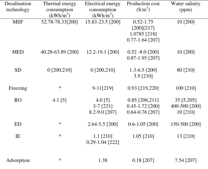
Gas hydrate formation involves high pressure conditions, and therefore appropriate equipments are required to design a hydrate–based process. Indeed, operating costs could be significantly higher compared to standard processes (distillation, reverse osmosis…). This cost drawback is the reason hydrate-based desalination has not been commercialized yet. As discussed earlier, the use of CP as guest for desalination in combination with other applications, such as gas capture/separation, or cold energy storage (see later in section 6.2), might be advantageous or profitable.
30
Remember that, with CP, hydrate crystallization occurs at only one bar under normal atmospheric pressure. In addition, CP can be recovered easily after hydrate dissociation since it is not miscible into water. This simplicity is an enormous advantage, and this is probably why CPH-based desalination is still of interest in the scientific community.
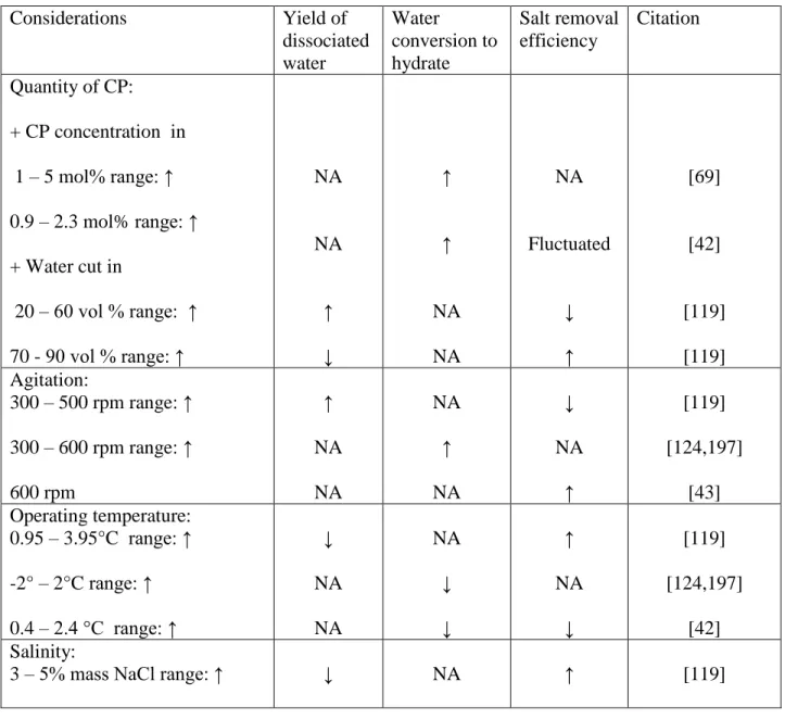
Recently, the use of CPH for desalination has been investigated at both laboratory and pilot scales [42,43,69,119,124,186,188,196–198] considering three main concerns: yield of dissociated water from CPH, water conversion to hydrate, and salt removal efficiency. The effects of mentioned considerations on CPH-based desalination process are detailed in Table 8.
Table 8. Effect of various considerations on CPH-based desalination process
Considerations Yield of dissociated water Water conversion to hydrate Salt removal efficiency Citation Quantity of CP: + CP concentration in 1 – 5 mol% range: ↑ 0.9 – 2.3 mol% range: ↑ + Water cut in 20 – 60 vol % range: ↑ 70 - 90 vol % range: ↑ NA NA ↑ ↓ ↑ ↑ NA NA NA Fluctuated ↓ ↑ [69] [42] [119] [119] Agitation: 300 – 500 rpm range: ↑ 300 – 600 rpm range: ↑ 600 rpm ↑ NA NA NA ↑ NA ↓ NA ↑ [119] [124,197] [43] Operating temperature: 0.95 – 3.95°C range: ↑ -2° – 2°C range: ↑ 0.4 – 2.4 °C range: ↑ ↓ NA NA NA ↓ ↓ ↑ NA ↓ [119] [124,197] [42] Salinity:
31
0.17 – 5% mass NaCl range: ↑ NA ↓ NA [124,197]
Use of graphite ↑ NA ↑ [43]
Use of filtering NA NA ↑ [69,124,196,197]
Use of centrifuging NA NA ↑ [69]
Use of washing
By 3.5 % mass brine water By fresh water By fresh water By DI water By filtered water ↑ ↑ NA NA NA NA NA NA NA NA ↑ ↑ ↑ ↑ ↑ [119] [119] [69,196] [124,188,197] [124,197] Ratio of washing water/dissociated water (g/g) 0.1 – 0.5 range: ↑ 0.5 – 1.2 range: ↑ 0.02 – 0.03 range: ↑ 0.03-0.05 range: ↑ 0 – 0.035 range: ↑ 0.035 – 0.05 range: ↑ Fluctuated Fluctuated NA NA NA NA NA NA NA NA NA NA ↑ Fluctuated ↑ ↓ ↑ ↓ [119] [119] [69] [69] [196] [196] Use of sweating NA NA ↑ [69]
Use of gravitational separating NA NA ↑ [124,197]
Use of spray injecting Use of tube injecting
NA NA ↑ ↑ NA NA [124,197] [124,197] where ↑: increase; ↓: decrease, NA: Not Acknowledge
Removal efficiency, yield of dissociated water, water conversion to hydrate, ratio of washing water/dissociated water (g/g), CP concentration, and water cut were calculated as follows: Yield of dissociated water = m1
mo ×100% or =
V1
32
where mo/Vo are the mass/volume of initial salt solution, and m1/V1 are the mass/volume of
melted water [43,119].
Water conversion to hydrate = mc
mo ×100% (2)
where mc is the mass of water converted to hydrates [42,69,124,196,197].
Salt removal efficiency = C0 - C1
C0 ×100% (3)
where C0 is weight percent of NaCl in prepared brine and C1 is that in dissociated water
[42,43,69,119,124,196,197].
Ratio of washing water/dissociated water = m2
m1 ×100% (4)
where m2 is the mass of water used for washing [119]
CP concentration = nCP
nbrine ×100% (5)
where
n
CP is the mole number of CP andn
brineis the mole number of initially prepared brine[42,69]. This is somewhat related to another parameter in the literature, the “Water cut”. Water cut = Vbrine
Vbrine +VCP×100% (6)
where
V
brine is the volume of initially prepared brine andV
CPis the volume of CP [119]In the next sections, some details are provided to explain the effects of some considerations on the CPH-based desalination process.
5.1 Quantity of CP.
Water cut can be used to indicate quantity of CP as described by Equation (6). When water cut increases, quantity of CP then decreases because these two parameters are inversely proportional to each other.
Table 8 illustrates that the water conversion into hydrate increases by raising the CP concentration in the system [42,69]. Also, the salt removal efficiency varies irregularly from less than 70% to close to 90% when increasing CP concentration from 0.9 to 2.3 mol % [42]. Moreover, the water cut can affect the yield of dissociated water and the salt removal efficiency differently [119]. The yield of dissociated water first augments significantly with water cut from 20% to 60% while the removal efficiency declines inappreciably. When the water cut is in 60% - 90% range, the yield tends to lessen considerably while the removal efficiency is slightly improved. To summarize, the removal salt efficiency for different water cut varies from 75% to 85%. This demonstrates that, compared to high water cut systems (>80 vol% water or <5 mol%
33
CP [42,69]), extra CP addition in brine could considerably improve the yield of dissociated water while the removal efficiency undergoes a relatively minor change.
The effect of CP quantity on the hydrate formation rate is described in elsewhere [42,119,126,127]. It was found that excess CP can increase notably the kinetics of hydrate formation, and hence the conversion of water to hydrate and the yield of dissociated water.
5.2 Agitation
Change in flow condition, or shear rate, is observed using various stirring rates. This leads to different mass and heat transfer rates in the system. Table 8 shows that boosting the agitation rate promotes water conversion and yield of dissociated water, as examined by different authors [39,43,60,70,119,124,125,197]. However, this comes with a decrease in salt removal efficiency [119]. Indeed, higher agitation rates may enhance the reaction kinetic and hence cause formation of smaller hydrate crystals with larger specific surface area. As a hydrate surface is hydrophilic, more salt ions tend to attach on the crystal surfaces, leading to a difficult separation of brine from hydrate [119].
The way CP is introduced into a system can also change the hydrate formation kinetics. Xu et al [124,197] declared that, by using the CP spray injection method, higher water conversion can be achieved, due to the smaller CP droplets created by the spray injection. However, a pump is hence needed for CP injection in this case, thus more energy is required.
5.3 Operating temperature
Table 8 indicates that the operating temperature affects strongly water conversion to hydrate, yield of dissociated water, and removal efficiency. At higher operating temperature, the hydrate formation rate decreases due to decrease in the driving force (here subcooling). Thus, both water conversion and yield of dissociated water are reduced with higher operating temperature [42,119,124,197].
However, two different observations in purification efficiency when increasing operating temperature were reported by Beak et.[42] and Lv et al.[119].
One the first hand, Beak et al. elucidated that, at operating temperature of 2.4°C, the purification is less efficient than at 0.4°C. This is attributed to higher attractive force between CPH particles. Certainly, adhesion forces between CPH particles increase linearly with rising temperature [199].
34
Thus, at higher temperatures, growing CPH crystals adhere to each other in a stronger framework than at lower temperatures. Consequently, more brine is trapped between CPH crystals, and a post-treatment method, such as centrifuging, is required.
One the second hand, Lv et al.[119] showed that the salt removal efficiency improves when increasing operating temperature from 0.95 to 3.95°C (or 274.1 – 277.1K). It was found that the residual salinity is likely to be strongly related to the shapes and size of hydrate crystals. Kishimoto et al. [87] specified that the size of the hydrate crystals diminished with subcooling increase.
Moreover, by using the FBRM probe, Lv et al.[119] indicated that the median chord length of CPH particles after 8h formation at 0.95 °C (274.1 K) is 22.16 μm, while, particles formed at 3.95°C (277.1 K) under the same other conditions exhibited a median chord length of 34.15 μm. Thus, it was supposed that at higher operating temperature (or lower subcooling), hydrate particles are bigger with a smaller specific surface area favorableto salt removal [119].
To sum up, in order to clarify the effect of operating temperature on the purification efficiency, more data at a varied range of operating temperature and salt concentration would be needed.
5.4 Salinity
Table 8 shows that the salt removal efficiency increases slightly with the salinity increase, while both water conversion to hydrate and yield of dissociated water appear to decrease considerably [119,124,197]. Indeed, when there is uptake in salt concentration, the driving force for hydrate formation decreases [28,119,124,197]. This reduces the CPH formation rate [39,68,87,119]. As a result, less water converts into hydrate under higher salt concentrations.
Moreover, an enhancement in purification efficiency at high operating temperatures can be attributed the CPH crystals size change. Indeed, the hydrate formation kinetics decreases as salt concentration increases [39,68,87,119]. Thus, bigger hydrate particles with a smaller specific area are likely to form. Consequently, there is less brine trapped between CPH crystals.
5.5. Solid additives
As aforementioned, the addition of some solid additives can promote CHP formation [43,61,75,129,130]. Moreover, Li et al [43] reported that the addition of graphite not only enhances CPH formation but also boosts the salt removal efficiency. They indicated that the
35
surface functional groups of graphite improve both hydrate nucleation and growth of CPH. Moreover, the hydrophobic surfaces of graphite could inhibit hydrate aggregation and make hydrate crystal particles more porous. Consequently, the trapped salt ions can be removed more easily by centrifuging process, thus increasing the salt removal efficiency [43]. In addition, in presence of graphite, the prolongation of hydrate formation improved the desalting efficiency [43]. The hydrophobic behavior of graphite is believed to play a crucial role in this improvement [43]. These findings present interesting perspectives for the use of graphite or carbon material surfaced in the development of CPH-base desalination techniques.
5.6 Post-treatment methods
In order to remove salts trapped onto the hydrate surfaces, some post-treatment methods are introduced, such as filtration, centrifuging, sweating, gravitational separation, and washing. Several studies concluded that all these techniques can enhance profoundly the salt removal efficiency [69,119,124,196,197].
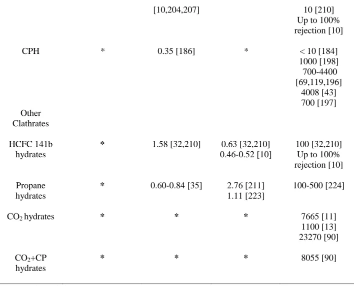
About 60-63% of NaCl from the feed solution was removed after CPH formation with only vacuum filtration [69,196]. It means that the treated water still contained a high level of NaCl. Obviously, this level of water purification is insufficient for desalination, so further post-treatments are needed.
Han et al. [69] demonstrated that centrifuging can enhance salt removal efficiency up to 96%. However, centrifuging is very expensive for mass treatment. Sweating by melting the impure zone over time can be a potential process to enhance salt removal. Nonetheless, it reduces the quantity of water retrieved. Moreover, this process is time consuming, hence an optimal time should be determined for the sweating of CPH crystal [69].
Washing is also an effective approach to enhance salt removal [69,119,124,196,197]. The source of the wash can be fresh, DI water, filtered water, or even brine water. The effect of washing water/produced water ratio on salt removal was remarkable. Han et al. [69,196] indicated that the optimal ratio of washing water/ produced water is approximately 0.03 (g/g) with a salt removal efficiency above 90%. Lv et al. [119] suggested that this value should be 0.5 (g/g) in order to remove enough salt from CPH crystals. However, this value is extremely high for industrial scales. Therefore, more investigation is required to optimize this ratio in order to meet the requirement of water purification and reduce the costs of desalination process.


![Figure 4. CPH-based desalination process diagram (inspired by [198])](https://thumb-eu.123doks.com/thumbv2/123doknet/11644700.307626/43.918.106.848.513.809/figure-cph-based-desalination-process-diagram-inspired.webp)
