Science Arts & Métiers (SAM)
is an open access repository that collects the work of Arts et Métiers Institute of
Technology researchers and makes it freely available over the web where possible.
This is an author-deposited version published in:
https://sam.ensam.eu
Handle ID: .
http://hdl.handle.net/10985/7627
To cite this version :
Brahim TLILI, Corinne NOUVEAU, Gildas GUILLEMOT - Elaboration, characterization of Cr-N
based coatings - In: International conference on Advances in Materials and Processing
Technologies (AMPT), France, 2010-10 - AIP Conference Proceedings - 2010
Any correspondence concerning this service should be sent to the repository
Administrator :
archiveouverte@ensam.eu
CP1315, International Conference on Advances in Materials and Processing Technologies (AMPT2010) Edited by F. Chinesta, Y. Chastel, and M. El Mansori
© 2010 American Institute of Physics 978-0-7354-0871-5/10/$30.00
Elaboration, characterization of CrN- based coatings
B. Tlili
a,b, C. Nouveau
b, G. Guillemot
ca UR. Mécanique Appliquée, Ingénierie et Industrialisation (M.A.2I), ENIT, BP 37, Le Belvédère, 1002 Tunis,
Tunisie
b Laboratoire Bourguignon des Matériaux et Procédés (LaBoMaP), Centre Arts et Métiers ParisTech de Cluny,
Rue Porte de Paris, F-71250 Cluny, France
c LMPGM, UMR-CNRS 8517, CER Arts et Métiers ParisTech, 8, Boulevard Louis XIV
59046 Lille, France
Abstract. Cr, CrN and CrAlN monolayers were synthesized by RF dual magnetron sputtering on
AISI4140 steel and silicon substrates at 200°C. Multilayers coatings based on the three mono-layers such as CrN/CrAlN and Cr/CrN/CrAlN were also synthesized only on Si. The physico-chemical and mechanical properties of the layers were determined by AFM, SEM+WDS, stress, roughness and nanoindentation measurements. The influence of the thickness on the mechanical properties of the monolayers stresses has been studied and as a consequence we compared the mono and multilayers stress state.
Keywords: Cr-N system, multilayers, thickness, residual stress.
INTRODUCTION
A variety of multilayer systems such as TiN/CrN [1], TiAlN/CrN [2], TiN/TiAlN [3], etc.,
have been studied extensively. However, there are very few reports on the multilayer coatings
based on CrN and CrAlN [4]. The addition of Al to CrN system permits to work at higher
temperatures where the oxidation occurs [5]. CrAlN coatings have been reported to be stable
up to a temperature of 900°C depending upon the Al content in the coatings [6]. CrAlN
coatings also exhibit higher hardness and a lower friction coefficient compared to CrN
coatings [7]. The new ternary film structure brought about significant advances in coating
designs, such as the decrease of the grain size and the formation of grain boundaries between the two phases. As a consequence, it is reported that CrAlN films exhibited excellent
mechanical properties and oxidation resistance owing to their solid solution structure [8].
Furthermore, it is well known that most properties of these solid solution composite films are influenced by certain factors such as crystalline structure and micro-structure. These factors led to the study of the multilayers coatings of CrN/CrAlN and Cr/CrN/CrAlN, in which the properties of Cr, CrN and CrAlN can be combined. The Cr underlayer is considered as a bonding layer.
In this work, we have investigated the effect of thickness on residual stress and hardness of the monolayers. Moreover, the relationship between mechanical properties and the stress state of the multilayers coatings was also discussed and established.
EXPERIMENTAL PROCESS
Deposition
The layers were deposited on mechanical polished steel (AISI 4140) and silicon (100) substrates using an RF dual magnetron sputtering system (NORDIKO type 3500-13, 56 MHz) equipped with two targets of high purity (Cr of 99.995 % and Al of 99.999 %) (Fig.1).
FIGURE 1. Plasmas operated in the magnetron chamber
Before deposition, the substrates and the targets were etched in pure argon plasma for 10 min. In order to obtain uniform coatings, the substrate was positioned 80mm away from the target. Very high purity nitrogen was introduced into the vacuum chamber as the reactive
gas. The residual pressure was 10-7 mbar. The deposition conditions such as the target bias
voltage, the deposition time and the gas mixture are given in Table 1.
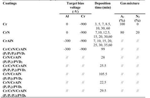
Table 1. Deposition conditions (The target power and the gas pressure are fixed to 4kW and 4µbar respectively)
Coatings Target bias
voltage (-V)
Deposition
time (min) Gas mixture
Al Cr Ar (%) (%) N2 Cr 0 -900 3, 5, 7, 8.5, 100 0 10, 30, 60 CrN 0 -900 7,10, 12.5, 80 20 15, 20, 30,60 CrAlN -300 -900 7, 10, 15, 20, // // 25, 30, 35,60 Cr/CrN/CrAlN -300 -900 99 // // (Pt/Pt/Pt):PVD1 CrN/CrAlN // // 28 // // (Pt/Pc):PVD2 Cr/CrN/CrAlN // // 25.5 // // (Pt/Pc/Pc):PVD3 CrN/CrAlN // // 105.5 // // (Pt/Pt):PVD4 CrN/CrAlN // // 22.5 // // (Pc/Pc):PVD5 Cr/CrN/CrAlN // // 29.5 // // (Pc/Pc/Pc):PVD6
Where Pc is the highest residual stress where the layers show a peak on the curve “stress vs
thickness” and Pt is the lower and stable residual stresses of the films. In the following text,
the films will be called PVDi (with i=1, 2, 3, 4, 5 and 6) as mentioned in Table 1.
Experimental
The atomic percentages of N, Cr and Al were determined by Wavelength Dispersive Spectrometry (WDS) microanalysis with a Jeol JSM-5600 Lv Scanning Electron Microscope (SEM). The surface roughness and thickness of the layers were observed and determined by Atomic Force Microscopy (AFM alpha300 A) and a 3D optical profilometer (NT-1100 Veeco Instruments Inc.) respectively. The hardness and the Young’s modulus of the layers were determined by nanoindentation (MTS Systems Corporation, XP®) using a Berkovich diamond tip and continuous stiffness option, with a maximum indentation depth of 2000 nm.
A theoretical model developed by A. Iost et al. [9] was applied to determine the hardness of
the coatings. The residual stresses (σ) were determined by interferometry (method of the
Newton’s rings) and calculated thanks to the Stoney’s equation [10].
RESULTS AND DISCUSSIONS
Coatings thickness, composition and roughness
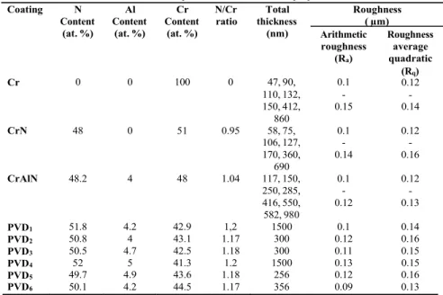
The Cr, CrN and CrAlN coatings were deposited with different thicknesses in order to determine the influence of the thickness on the residual stress. Taking into account the optimal conditions obtained on monolayer, we developed multilayer coatings of Cr/CrN/CrN and CrAlN/CrAlN. The relative composition, thickness, morphology of the films determined by EDS, WDS and 3D optical profilometer was resumed in Table 2.
Table 2. The composition of films in atomic proportion Coating N
Content Content Al Content Cr N/Cr ratio thickness Total Roughness ( µm)
(at. %) (at. %) (at. %) (nm) Arithmetic
roughness (Ra) Roughness average quadratic Cr 0 0 100 0 47, 90, 0.1 (R0.12 q) 110, 132, - - 150, 412, 0.15 0.14 860 CrN 48 0 51 0.95 58, 75, 0.1 0.12 106, 127, - - 170, 360, 0.14 0.16 690 CrAlN 48.2 4 48 1.04 117, 150, 0.1 0.12 250, 285, - - 416, 550, 0.12 0.13 582, 980 PVD1 51.8 4.2 42.9 1,2 1500 0.1 0.14 PVD2 50.8 4 43.1 1.17 300 0.12 0.16 PVD3 50.5 4.7 42.5 1.18 300 0.11 0.15 PVD4 52 5 41.3 1.2 1500 0.13 0.15 PVD5 49.7 4.9 43.6 1.18 256 0.12 0.16 PVD6 50.1 4.2 44.5 1.17 356 0.09 0.13
s e s s u s e r l u d t o m s s l a s s e ' g n n d i s u e R r a H o Y s e s s e r t s l a u d i s e R s u l u d o m s ' g n s s e n d r a H s e s s e r s u l u d o m s t s s s e n d l a u d ' g n u o Y i s e R r a H
The N/Cr ratio varied from 0.95 to 1.2 for all the coatings, which reflects their stoichiometry.
Furthermore, the Ra and Rq roughness of the films are low, and their variations do not exceed
4/100 on all surfaces. On the other hand the evolution of the thickness versus the deposition time is always linear.
Coating hardness, Young’s modulus and residual stress
We were interested to verify the influence of the layers thickness on their hardness,
Young’s modulus and residual stress. Fig.2 shows that the evolution of the hardness and
Young’s modulus is closely related to internal stresses of the layers whatever the layer is. The residual stresses peak close to the interface between the substrate and the monolayers confirm
the results obtained by Nouveau et al. [11] and Hanabusa et al. [12] and can be explained by a
growth model defined in [11]. The evolution of the Young’s modulus is similar with the
hardness one versus the layers thickness.
A/ 300 250 200 10 5 0 r (-GPa) H (GPa) E (GPa) 0 200 400 600 800 1000 Thickness (nm) B/ 350 300 250 200 20 15 10 5 0 (-GPa) r H(GPa) E(GPa) 0 100 200 300 400 500 600 700 Thickness (nm) C/ 250 (-GPa) r H (GPa) E (GPa) 200 10 5 0 0 200 400 600 800 1000 Thickness (nm)
FIGURE 2. Evolution of the hardness, Young’s modulus and residual stresses as a function of the A/ Cr, B/
CrN and C/ CrAlN film thickness
All monolayers coatings showed significantly higher hardness as compared to substrate AISI4140 (4.2 GPa). The maximum hardness for Cr, CrN and CrAlN was measured and was 12, 18 and 12.5 GPa respectively. The greatly enhanced mechanical properties of thin films can be explained by solid mixed hardening, complex chemical bonding strengthening, and the novel nanocomposites microstructure that enhances the material strength by a dislocation blocking effect. An explanation of the high hardness of the thin films near the interface with
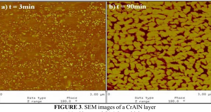
substrate was the local bond strengthening and dislocation motion limited by lattice distortion during germination and growth. According to the amorphous/crystalline nanocomposite design concept, the high hardness of the composite film near the interface was based on the combination of the lack of the dislocation activity in the small nanocrystals and the jamming of grain boundary sliding by the formation of a strong interface between the two phases. The films investigated here had crystallite sizes and amorphous layer thickness similar to the super hard nanocomposites, which were sufficient for formation of nanosized dislocations. At the beginning of the deposition, many nuclei of tiny islands are formed on the substrate surface
(Fig. 3a). Since these nuclei are tiny, the stress is considered to be significantly small. As
depositing time increases, these tiny nuclei coalesce with each other to form islands (Fig. 3b)
and finally change into a solid film on the substrate. After this film formation, compressive stresses developed during the cooling stage will force the atoms through the grain boundaries as well as the film surface. These atomic migrations form hillocks at the grain boundaries on a film surface, bringing stress relaxation in films thicker than 150, 128 and 110 nm for CrAlN, CrN and Cr, respectively. Moreover, this explanation seems useful for hardness; because smaller the grains size is, higher the hardness is. This explains the proportionality between the residual stresses and hardness.
FIGURE 3. SEM images of a CrAlN layer
(a) 50 nm and (b) 1.8µm thick.
Moreover, Fig.4 shows that residual stresses in multilayers are lower than the monolayers
ones. The reduction of the residual stresses in multilayer coatings compared to those of the monolayers is also mainly due to their interface. The interlayers seem to be effective in absorbing residual stresses during film growth. It’s obvious that their values strongly depend on the residual stresses of the monolayers. Indeed, the total stress is increase 3.4 times when
we compare PVD1 (all the monolayers are at Pt) with PVD6 (all the monolayers are at Pc). The
highest stress is obtained for the PVD6 multilayer, where the monolayers presented their stress
peak, which reflects this proportionality. Besides, the same results is obtained when we
compare PVD4 and PVD5, the stress is also increased 3.5 times. Actually, if we compare the
PVD1 and PVD4 or PVD5 and PVD6 multilayers, it’s obvious that the underlayer of Cr has a
main effect because the Cr bonding or transition layer played a main role on the stress
intensity, which proves that the stress level on the coating PVD6 (-1.2 GPa) is higher than that
in the PVD5 (- 0.7GPa) one for example. We can also note if we compare PVD2 and PVD5
that the stress remains almost the same whatever the CrN stress state (~0.65-0.7GPa). A
similar result is obtained when we compare the PVD3 and PVD6 multilayers stress with a Cr
underlayer (~1.1-1.2GPa). These results mean that the Cr or CrN underlayers improve the
7 5 6 4 3 2 3 D 2 D 5 D 6 D 4 D 1 D Sig m a (-GP a)
underlayers are at their Pt point and the sublayers at their Pc point, then the increase of the
stress is due to the fact that these layers present their highest stress (ex. PVD4 compared to
PVD2 or PVD1 compared to PVD3). Finally, these results would help in the choice of
multilayers according to their future applications (mechanical, thermal, wear etc…).
1,4 1,2 1,0 0,8 0,6 0,4 0,2 0,0 Film s
FIGURE 4. Residual stress of multilayer coatings
CONCLUSIONS
According to the previous results, we can conclude as follows:(1) The CrAlN, CrN and Cr monolayers presented a residual stress peak that can be related to germination, growth and morphology of the film near the interface film / substrate.
(2) The hardness and Young’s modulus of the monolayers depend on their residual stresses (3) The residual stresses of multilayer coatings are always lower than the monolayers ones.
This decrease is related to the interface between layers, and the variation of the thickness. Besides, the final residual stresses of the multilayers depend on the stress state of the monolayers from whom they are built with. For example, if you want a stressed so a hard coating, you should select one with a Cr underlayer (whatever its stress state) and a
sublayer at its Pc stress point. For a lower final stress, we would select no Cr underlayer or
all the monolayers at their Pt stress point.
REFERENCES
[1] H.A. Jehn, M.E. Baumggartner, Surf. Coat. Technol. 108, 54-55 (1992)[2] M. Panjan, S. Šturm, P. Panjan, M. Čekada, Surf. Coat. Technol. 202, 815-819 (2007)
[3] L.A. Dobrzaňski, M. Polok, M. Adamiak, Journal of Materials Processing Technology 164-165, 843-849
(2005)
[4] Youn J. Kim, Tae J. Byun, Jeon G.Hon, Superlattices and Microstructures 45, 73-79 (2009)
[5] P.H. Mayrhofer, H. Willmann, C. Mitterer, Surf. Coat. Technol. 222, 146 -147 (2001)
[6] M. Kawate, A.K. Hashimoto, T. Suzuki, Surf. Coat. Technol. 165,163 (2003).
[7] Y. C. Chim and al., Thin Solid films 517, 4845- 4849 (2009)
[8] M. Uchida, N. Nihira, A. Mitsuo, K. Toyoda, K. Kubota, T. Aizawa, Surf. Coat. Technol. 627, 177-178 (2004).
[9] K. Rahmoun, A. Iost, V. Keryvin, G. Guillemot, N.E. Chabane Sari, Thin Solid Films 518, 213-221 (2009)
[10] Y. Lifshitz, Diam. Relat. Mater. 5, 388 (1996)
[11] S.K. Pradhan, C. Nouveau, A. Vasin, M.-A. Djouadi, Surf. Coat. Technol. 200, 141-145 (2005)