HAL Id: hal-01988619
https://hal.laas.fr/hal-01988619
Submitted on 21 Jan 2019
HAL is a multi-disciplinary open access
archive for the deposit and dissemination of
sci-entific research documents, whether they are
pub-lished or not. The documents may come from
teaching and research institutions in France or
abroad, or from public or private research centers.
L’archive ouverte pluridisciplinaire HAL, est
destinée au dépôt et à la diffusion de documents
scientifiques de niveau recherche, publiés ou non,
émanant des établissements d’enseignement et de
recherche français ou étrangers, des laboratoires
publics ou privés.
A General Manipulation Task Planner
Thierry Simeon, Juan Cortés, Anis Sahbani, Jean-Paul Laumond
To cite this version:
Thierry Simeon, Juan Cortés, Anis Sahbani, Jean-Paul Laumond. A General Manipulation Task
Planner. Algorithmic Foundations of Robotics V. Springer Tracts in Advanced Robotics., pp.311-327,
2004. �hal-01988619�
Thierry Sim´eon, Juan Cort´es, Anis Sahbani, and Jean-Paul Laumond
LAAS-CNRS, Toulouse, France
Abstract. This paper addresses the manipulation planning problem which deals with motion planning for robots manipulating movable objects among static obsta-cles. We propose a general manipulation planning approach capable to deal with continuous sets for modeling both the possible grasps and the stable placements of the movable object, rather than discrete sets generally assumed by the existing planners. The algorithm relies on a topological property that characterizes the ex-istence of solutions in the subspace of configurations where the robot grasps the object placed at a stable position. This property leads to reduce the problem by structuring the search-space. It allows us to devise a manipulation planner that directly captures in a probabilistic roadmap the connectivity of sub-dimensional manifolds of the composite configuration space. Experiments conducted with the planner demonstrate its efficacy to solve complex manipulation problems.
Several applications such as robot programming, manufacturing or an-imation of digital actors require some real or virtual artifact to move and manipulate objects within an environment composed of obstacles.
Manipulation planning concerns the automatic generation of the sequence of robot motions allowing to manipulate movable objects among obstacles. The presence of movable objects, i.e. objects that can only move when grasped by a robot, leads to a more general and computationally complex version of the classical motion planning problem [14]. Indeed, the robot has the ability to modify the structure of its configuration space depending on how the mov-able object is grasped and where it is released in the environment. Motion planning in this context appears as a constrained instance of the coordinated motion planning problem. Indeed, movable objects can not move by them-selves; either they are transported by robots or they must rest at some stable placement. The solution of a manipulation planning problem consists in a sequence of sub-paths satisfying these motion restrictions. In related litera-ture (e.g. [2,14]), motions of the robot holding the object at a fixed grasp are called transfer paths, and motions of the robot while the object stays at a stable placement are called transit paths.
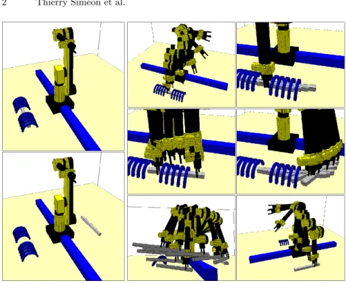
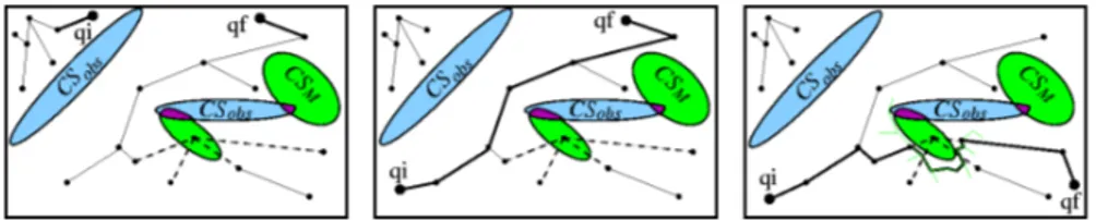
Consider the manipulation planning example illustrated by Figure 1. The manipulator arm has to get a movable object (the bar) out of the cage, and to place it on the other side of the environment. Solving this problem requires to automatically produce the sequence of transfer/transit paths separated by grasps/ungrasps operations, allowing to get one extremity of the bar out of the cage; the manipulator can then re-grasp the object by the extremity that was made accessible by the previous motions, perform a transfer path to
ex-Fig. 1. A manipulation planning problem (left) and its computed solution (right)
tract the bar from the cage, and finally reach the specified goal position. This example shows that a manipulation task possibly leads to a complex sequence of motions including several re-grasping operations. A challenging aspect of manipulation planning is to consider the automatic task decomposition into such elementary collisions-free motions.
Most of existing algorithms (e.g. [1,2,5,12,18]) assume that finite sets of stable placements and possible grasps of the movable object are given in the definition of the problem. Consequently, a part of the task decomposition is thus resolved by the user since the initial knowledge provided with these finite sets has to contain the grasps and the intermediate placements required to solve the problem. Referring back to the example, getting the bar out of the cage would require a large number of precise grasps and placements to be given as input data.
In this paper, we describe a more general approach based onto recent re-sults presented in [22,23]. The proposed approach is capable to deal with a continuous setting of the manipulation problem. It allows us to design a ma-nipulation planner that automatically generates among continuous sets the grasps and the intermediate placements required to solve complicated manip-ulation problems like the one illustrated onto Figure 1. The approach relies on a topological property first established in [3] and recalled in Section 1. This property allows us to reduce the problem by characterizing the existence of a
solution in the lower dimensional subspace of configurations where the robot grasps the movable object placed at a stable position. Section 2 describes the proposed two-stage approach. First, Section 2.1 shows how the connected components of this sub-space can be captured in a probabilistic roadmap computed for a virtual closed-chain system. Using the visibility technique [20] extended to deal with such closed systems [7], this first stage of the approach captures the connectivity of the search space into a small roadmap generally composed of a low number of connected components. Connections between these components using transit or transfer motions are then computed in a second stage (Section 2.2) by solving a limited number of point-to-point path planning problems. The details of an implemented planner interleaving both stages in an efficient way are described in Section 3. Finally, we discuss in Section 4 some experiments and the performance of the planner.
1
Problem Statement
Let us consider a 3-dimensional workspace with a robotR and a movable ob-jectM moving among static obstacles1. The robot has n degrees of freedom
andM is a rigid object with 6 degrees of freedom that can only move when it is grasped by the robot. Let Crob and Cobj be the configuration spaces of
the robot and the object, respectively. The composite configuration space of the system is CS = Crob× Cobj and we call CSf ree the subset in CS of all
admissible configurations, i.e. configurations where the moving bodies do not intersect together or with the static obstacles.
Manipulation Constraints: A solution to a manipulation planning problem corresponds to a constrained path in CSf ree. Such a solution path is an
alternate sequence of two types of sub-paths verifying the specific constraints of the manipulation problem, and separated by grasp/ungrasp operations:
• Transit Paths where the robot moves alone while the object M stays sta-tionary in a stable position. The configuration parameters ofM remain constant along a transit path. Such motions allow to place the robot at a configuration where it can grasp the object. They are also involved when changing the grasp of the object.
• Transfer Paths where the robot moves while holding M with the same grasp. Along a transfer path, the configuration parameters qobj of M
change according to the grasp mapping induced by the forward kinematics of the robot: qobj = g(qrob).
Let P (resp. G) denote the set of stable placements (resp. grasps) ofM. Both types of paths lie in lower dimensional sub-spaces of CSf ree. These
sub-spaces are defined as follows:
1
• The Placement space CP is the sub-space of CSf ree defined as the set of
free configurations where the mobile object is placed at a stable position, i.e. a position p ∈ P at which M can rest when it is not grasped by the robot. Each transit path lies in CP . However, note that a path in CP is not generally a transit path since such path has to belong to the sub-manifold corresponding to a given placement p.
• The Grasp space CG is the sub-space of CSf ree defined as the set of
free configurations under all possible grasps g ∈ G of the object M. A transfer path belongs to the sub-manifold defined by a particular grasp kept constant along the path.
Problem: Given the two sets (discrete or continuous) P and G defining the stable placements and feasible grasps, the manipulation planning problem is to find a manipulation path (i.e. an alternate sequence of transit and transfer paths) connecting two given configurations qi and qf of CG∪ CP .
Manipu-lation planning then consists in searching for transit and transfer paths in a collection of sub-manifolds corresponding to particular grasps or stable place-ments of the movable object. Note that the intersection CG∩ CP between the sub-manifold defines the places where transit paths and transfer paths can be connected. The manipulation planning problem appears as a con-strained path planning problem inside (and between) the various connected components of CG∩ CP .
1.1 Discrete Case
In the case of a discrete number of grasps and stable placements, the inter-section CG∩ CP consists of a finite set2of configurations. In this case, it is
possible to build a Manipulation Graph (M G) where each node corresponds to a configuration of CG∩ CP , and edges are constructed by searching for transfer (or transit) paths between nodes sharing the same grasp (or place-ment) of the mobile object(s).
Most implemented manipulation planners consider that such discrete sets P and G are given as input to the planner. The general framework proposed in [2] for one robot and several moving objects with discrete grasps and placements was first implemented for two simple robots: a translating polygon [2] and a 3dof planar manipulator [15]. This framework was extended in [11,12] to multi-arm manipulation planning where several robots cooperate to carry a single movable object amidst obstacles. The planner proposed in [12] first plans the motions of the movable object using a RPP technique [4], and then finds the transfer/transit motions of the arms to move the object along the computed path. This heuristic approach led to impressive
2
Note however that the case of a redundant robot considered in [1] also leads to an infinite cardinality of the set CG∩ CP .
results for solving realistic problems. Another heuristic planner proposed in [5] iteratively deforms a coordinated path first generated in the composite configuration space using a variational dynamic programming technique that progressively enforces the manipulation constraints.
More recently, two other contributions extended existing planning tech-niques to manipulation planning. In [1], the Ariane’s Clew algorithm [6] is applied to a redundant robot manipulating a single object in a 3D workspace. The method assumes discrete grasps of the movable object; it is however capa-ble to deal in realistic situations with redundant manipulators for which each grasp possibly corresponds to an infinite number of robot configurations (i.e. the cardinality of CG∩ CP is infinite). Finally, [18] proposed another prac-tical manipulation planner based onto the extension of the PRM framework [10,19]. The planner builds as in [2] a manipulation graph between discrete configurations of CG∩ CP , but connections are computed using a Fuzzy PRM planner that builds a roadmap with edges annotated by a probabil-ity of collision-freeness. Such roadmaps improve the efficiency of the planner for solving the possibly high number of path planning queries in changing environments required to compute the connections.
1.2 Continuous Case
The structure of the search space is more complex when dealing with continu-ous sets P and G. For example, one may describe the set of stable placements by constraining the movable object to be placed on top of some horizontal faces of the static obstacles; such placement constraints would define P as a domain in a 3-dimensional manifold of CSobj(two translations in the
horizon-tal place and one rotation around the vertical axis). Also, one may consider G as a set of continuous domains such that the jaws of a parallel gripper have a sufficient contact with two given faces ofM. With such grasp constraints, G also corresponds to a 3-dimensional manifold (two translations parallel to the grasped faces and one rotation around the axis perpendicular to the faces).
In such cases, CG∩ CP is defined by continuous configuration domains. Extending the notion of manipulation graph to continuous domains, first requires that the connectivity of CG∩ CP adequally reflects the existence of a manipulation path. This is not a priori obvious since paths computed in CG∩ CP correspond to a continuous change of the grasp, while transfer paths need to stay in the sub-manifold defined by a constant grasp.
Reduction Property: It is shown in [3]3that two configurations which are in a
same connected component of CG∩ CP can be connected by a manipulation path. This property means that any path in CG∩ CP can be transformed into a finite sequence of transit and transfer paths. It is then sufficient to
3
Note that this property only holds for a single movable object under the hypoth-esis that the robot does not touch the static obstacles
study the connectivity of the various components of CG∩ CP by transit and transfer paths.
Manipulation Graph: The reduction property allows to extend the Manipula-tion Graph to the continuous case: M G0s nodes correspond to the connected components of CG∩ CP and an edge between two nodes indicates the ex-istence of a transit/transfer path connecting two configurations of different connected components. This property was used in [3] to derive, for the spe-cific case of a translating polygonal robot, a cell decomposition algorithm capable to manipulate one movable polygon with an infinite set of grasps.
2
A General Approach to Manipulation Planning
We now describe a more general approach for solving manipulation prob-lems under continuous manipulation constraints. The main idea is to exploit the reduction property of Section 1 to decompose the construction of the manipulation graph into the two following steps:
• compute the connected components of CG ∩ CP . Section 2.1 describes a method that directly captures the topology of CG∩ CP inside a prob-abilistic roadmap [10,19].
• determine the connectivity of these connected components using transit-paths and transfer-transit-paths. Section 2.2 explains the method used to com-pute such connections.
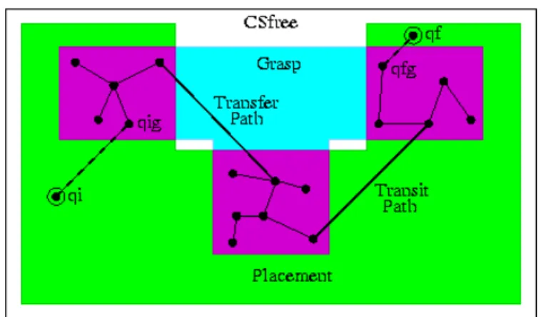
Fig. 2. Structure of the Manipulation Roadmap
Figure 2 illustrates the structure of a manipulation roadmap computed using this approach. The roadmap is structured into a small number of nodes
(the connected components of CG∩ CP ) connected with transit or trans-fer paths. Once the manipulation roadmap is computed, queries are solved by searching a path inside M G. Note that the obtained solution possibly alternates transfer/transit paths (when traversing edges of M G) with other elementary paths computed in CG∩ CP (inside nodes of MG) which do not correspond to feasible paths. However, thanks to the reduction property, any such CG∩ CP paths can be transformed in a post-processing stage into a finite sequence of transit and transfer paths.
2.1 Capturing CG∩ CP Topology via Closed-Chain Systems
The main critical issue is to capture into a probabilistic roadmap the topology of CG∩ CP which is a sub-manifold of the global configuration space with a lower dimension. The difficulty in using probabilistic roadmap approaches is to face sub-dimensional manifolds. Indeed the probability to choose a con-figuration at random on a given sub-dimensional manifold is null.
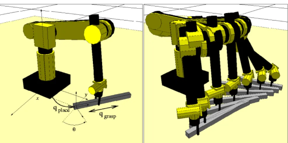
Fig. 3. Virtual closed-chain system and a feasible CG∩ CP motion (the bar moves on the floor while sliding into the gripper’s jaws)
The idea here is to explore CG∩ CP as such. For this, we consider that CG∩ CP is the configuration space of a single system consisting of the robot together with the movable object placed at a stable position. Maintaining the stable placement while the object is grasped by the robot induces a closed chain for the global system.
Figure 3 shows the example of a closed chain system formed by a 6dof arm manipulating a long bar. The bar moves in contact with the floor while sliding within the gripper. The sliding motion of the gripper results from the additional degrees of freedom qgrasp introduced in the system to
a translation of the parallel jaw gripper along the bar. Similarly, the set P of stable placements corresponds to the planar motions parameterized by a vector qplace= (x, y, θ) (two horizontal translations and a vertical rotation),
that maintain the contact of the bar with the floor. The motion shown in the Figure is a feasible motion in CG∩ CP . It is not admissible from the manipulation problem point of view. However, it can be transformed into a finite sequence of feasible transit and transfer paths.
We then propose to apply planning techniques for closed chain systems to capture the topology of CG∩ CP . Indeed, several recent contributions extended the PRM framework [10,19] to deal with such closed chain mech-anisms [17,9,7]. In particular, we use the algorithm [7] that demonstrated good performance onto complex 3D closed chains involving tenths of degrees of freedom. As initially proposed in [9] the loop is broken into two open sub-chains, but the random node generation combines a sampling technique called Random Loop Generator (RLG) with forward kinematics for the ac-tive chain and inverse kinematics for the remaining passive part of the loop in order to force the closure. The advantage of the RLG algorithm is that it that it produces random samples for the active chain that have a high probability to be reachable by the passive part. This significantly decreases the cost of computing and connecting closure configurations. The practical efficacy of our approach results from the good performance reached today by these closed-chain extensions of the PRM framework.
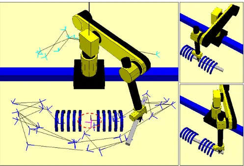
Fig. 4. A Visibility Roadmap computed in CG∩ CP (left) and two placements of the system inside two different connected components of CG∩ CP (right)
The CG∩ CP roadmap is computed using the Visibility-PRM technique [20,16]. This technique keeps the roadmap as small as possible by only adding two types of useful samples: guards that correspond to samples not already “seen” by the current roadmap, and connectors allowing to merge several con-nected components. Its interest is first to control the quality of the roadmap in term of coverage, and also to capture the connectivity of possibly com-plex spaces into a small data structure. We believe that the small size of the visibility roadmaps, combined with the proposed structuring of CG∩CP con-tributes to the overall efficiency of our approach by limiting the number of costly path-planning queries to be performed during the second stage, when searching the connections with collision-free transfer or transit paths.
Figure 4 shows the visibility roadmap computed in CG∩ CP by the algorithm for the introduction example shown in Figure 1. While the collision-free configuration space of the arm alone is connected, CG∩ CP is not. The computed roadmap has four connected components: two main components separated by the long static obstacle, and two other small components that correspond to placements of the movable object inside the cage obstacle while it is grasped by the arm through the open passage in the middle of the cage. These two small components (inside the dashed circle of the left image) correspond to a similar position of the bar, rotated or not by 180 degrees. One associated placement of the system is shown onto the top right image. The bottom right image corresponds to a node of the main component with the bar placed at the same position, but using a different grasp. Connecting this node to the small component is not possible because of the cage obstacle that limits the continuous change of grasp. Such re-grasping requires the computation of collision-free paths outside CG∩ CP as explained below.
2.2 Connections with transit and transfer paths
Consider two configurations in CG∩ CP that can not be directly connected by a collision-free path in CG∩ CP (i.e. configurations that do not belong to the same connected component of M G). These configurations correspond to fixed grasps and placements of the movable object, noted (gi, pi)i=1,2. The
problem is now to determine whether both configurations can be connected by collision-free transit/transfer paths searched inside the corresponding leaves of CP and CG. Such a connection is possible if there exists:
• a transfer path from (g1, p1) to (g1, p2) followed by a transit path from
(g1, p2) to (g2, p2).
• or a transit path from (g1, p1) to (g2, p1) followed by a transfer path from
(g2, p1) to (g2, p2).
We next explain the two-stage method used by the planner to solve these path-planning queries. Note that each query has to be performed in a partially modified environment since it corresponds to a particular grasp or placement
of the movable object. The motivation is simply to amortize the cost of deal-ing with such partial changes by re-usdeal-ing at each query some of the paths precomputed during the first stage by disregarding the movable object.
First, we compute a roadmap for the robot and the static obstacles, with-out considering the presence of the movable object. Then, before to solve a given (transit or transfer) path query, the roadmap is updated by checking whether each edge is collision-free with respect to the current position of the movable object. Colliding edges are labeled as blocked in the roadmap.
Fig. 5. Search into the labeled roadmap: a/ no solution exists b/ a solution is found c/ local update of the blocked edges
The search for a given path is then performed within the labeled roadmap. As illustrated by Figure 5, three cases possibly occur. When the search fails, this means that no path exists even in the absence of the movable object; the problem has no solution. Similarly, when the computed path does not contain any blocked edge (dashed edges onto the Figure) then a solution is found. Now let us consider the intermediate situation where the a path necessarily contains blocked edges. In such case, the algorithm tries to solve the problem locally by using a Rapid Random Tree (RRT) algorithm [13] to connect the endpoints of the blocked edges. The main interest of RRT is to perform well locally. Its complexity depends on the length of the solution path. This means that the approach quickly finds easy solutions. It may be viewed as a dynamic updating of the roadmaps.
3
Manipulation Planning Algorithm
We now describe in more details the algorithm that was developed to im-plement the approach presented above. The algorithm takes as input several classes of possible continuous grasps Gi. Each Gi is defined by a
transfor-mation matrix Tgi and a set of parameters, noted qgrasp, varying in a given interval. Similarly, several continuous regions of placement Pjcan be defined,
each characterized by a transformation matrix Tpj that defines a stable sit-uation of the object, and a vector qplace = (x, y, θ) representing two
horizon-tal translations inside a rectangular domain and a rotation around an axis perpendicular to this plane. For each couple of sets (Gi,Pj), the resulting
virtual closed-chain system is considered when analyzing the connectivity of CG∩ CP sub-spaces corresponding to the couple.
3.1 Building the Manipulation Graph
The algorithm incrementally constructs the manipulation graph M G by in-terleaving the two steps of the approach: computing CG∩ CP connected components and linking them. Following the principle of the Visibility-PRM technique, the algorithm stops when it is not able to expand the graph after a given number of tries (MAX NTRY). This number of failures is related to an estimated coverage of the composite configuration-space by M G.
EXPAND GRAPH(M G)
ntry← 0
expanded← FALSE
while (ntry < MAX NTRY(M P )) and (¬expanded) N← NEW NODE(MP )
expanded←EXPAND G∩P(MG,N)
if (¬expanded) and (TRY OTHER LINKS(ntry)) then expanded←CONNECT OUTSIDE G∩P(MG,N) ntry = ntry + 1
return expanded
The functionEXPAND GRAPHperforms one expansion step of M G. Can-didate nodes are first sampled in the CG∩ CP manifold and the different types of connections to the graph are then tested.
A candidate node N is generated as follows by the functionNEW NODE: it first randomly selects one of the Pj sets given as input to M P and a
sta-ble configuration p∈ Pj of the movable object is then chosen by randomly
sampling qplace. Similarly, one of the grasp classes Gi and the corresponding
parameters qgraspare also randomly chosen. The candidate node N is
gener-ated when the sampled grasps and placements are collision-free and feasible for the virtual closed system.
Following the discussion in Section 2.1, it is more efficient to explore CG∩ CP than to check connections outside. Therefore, the sample N is first used byEXPAND IN G∩Pwhich checks connections to the graph com-ponents using CG∩ CP paths. This function keeps N to expand the graph when the node creates a new component or merges existing components of the graph. In the other case, the choice of testing other connections with CON-NECT OUTSIDE G∩Pis made by the boolean functionTRY OTHER LINKS, based onto a biased random choice{True, False} that depends on the evolu-tion of the size of M G: the first expansion steps starts with a low probability to callCONNECT OUTSIDE G∩P; when the roadmap grows, this probability increases as the percentage of the coverage estimated by the fraction (1− 1
ntry)
(see [20] for details).
Expansion in CG∩ CP . The function EXPAND G∩P carries out the ex-ploration of the CG∩ CP manifold usingLINKED IN G∩P to test the link
EXPAND G∩P(MG,N)
nlinked comp.← 0
for i = 1 to N COMP(M G) do if LINKED IN G∩P(N,Ci) then
nlinked comp.= nlinked comp.+ 1
if nlinked comp.6= 1 then
ADD NODE(N, M G) UPDATE GRAPH(M G) return TRUE
else
return FALSE
between N and each connected component of M G by means of paths in CG∩ CP . Note that such connections can be achieved only with the nodes computed from the same couple (Gi, Pj) as the one used to generate N .
For each component Ci, nodes with such characteristics are tested until a
connection is feasible or all those nodes have been checked. The connections are determined from local paths computed in CG∩ CP for the virtual closed system induced by (Gi, Pj). Following the visibility principle, the node N is
added to the graph only if it was linked to none or to more than one connected component. In the second case, the linked components are merged.
Connections with transit and transfer paths. The functionEXPAND G∩Pfails when N can be linked by CG∩ CP paths to only one connected component of M G. In this case, the role ofCONNECT OUTSIDE G∩Pis to test the link to the other connected components using the composition of a transfer and a transit path, as explained in Section 2.2. FunctionLINKED OUTSIDE G∩P
tests the connection between N and each node of Ci using such paths. This
function stops checking a component when a valid connection is found. In such case the component of node N is merged with the linked Ci.
CONNECT OUTSIDE G∩P(MG,N)
nlinked comp.← 0
for i = 1 to (N COMP(M G)| Ci6=COMP(N)) do
if LINKED OUTSIDE G∩P(N,Ci) then
nlinked comp.= nlinked comp.+ 1
if nlinked comp.6= 0 then
UPDATE GRAPH(M G) return TRUE
else
3.2 Solving Manipulation Queries
Once the manipulation roadmap is built, queries can be performed using the three following steps. First, the start and goal configurations are connected to M G using theLINKED OUTSIDE G∩Pfunction described above and the manipulation graph is searched for a path between both configurations. The second step is necessary to transform CG∩ CP portions of the solution path into a finite sequence of transfer/transit paths. This is done by a simple pro-cedure that iteratively splits the CG∩ CP paths into pieces whose endpoints can be connected by a composition of two transit/transfer motions. Finally, the solution is smoothed by a procedure that eliminates unnecessary motions.
4
Experimental Results
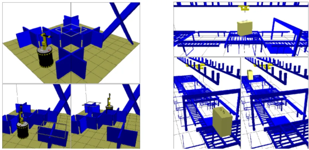
The manipulation planner was implemented within the software platform Move3D [21] currently developed at LAAS. Several environments have been used as test-bed of the planner. In this section, we present the results ob-tained onto three of them. The computation times correspond to experiments conducted on a 330MHz Sparc Ultra 10 workstation. The first example cor-responds to the problem of Figure 1. We refer to it as the Cage example. Two other scenes are shown in Figure 6: the left image illustrates a problem (MobM) involving a manipulator arm mounted onto a mobile platform. The right example (RoBr) corresponds to an industrial logistics problem treated in the framework of the European Project MOLOG 4 . The manipulation
device is a rolling bridge.
Fig. 6. Scenes and start/goal positions for the MobM and RoBr examples
4
Fig. 7. A CG∩ CP path with a sliding motion of the bar (left) transformed into a sequence of three feasible transfer/transit/transfer manipulation paths (right)
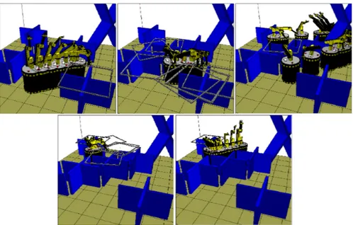
The difficulty with the Cage example is the complexity of the manipu-lation task. Several consecutive re-graspings motions through the middle of cage obstacle are necessary to move the bar to a position where it can be regrasped by its extremity. The planner automatically computes the required configurations from only one continuous placement domain (the floor) and one grasping zone all along the bar. The path to get the bar out of the cage is found in the CG∩ CP manifold, and then transformed during the post-processing step in a sequence of transit and transfer paths (see Figure 7). The final path contains 20 elementary paths with 8 re-graspings of the mov-able object. This difficult manipulation problem was solved in less than two minutes, which demonstrates the efficacy of the proposed approach.
In the example MobM, the mobile manipulator (9dof ) can only pass from one side of the scene to the other side through the passage under the X-shaped obstacle. However this passage is too narrow for the movable object
Fig. 9. Manipulation path computed for the RoBr problem
(the square frame). A continuous grasping set is defined all around this ob-ject. The frame can be placed on the central obstacles. Figure 8 shows the manipulation solution computed by the planner. Here, the manipulation task is simpler compared to the Cage example; less re-graspings are needed to solve the problem. The difficulty illustrated by the example is to deal with a re-dundant system. An infinite set of solutions exists to achieve the same grasp. Redundancy is a challenge when treating closed chain mechanisms. The ex-ploration of the CG∩ CP manifold for such systems is efficiently performed by using the approach in [7].
In the example RoBr, transporting the load between the extreme sides of the scene requires to generate an intermediate placement under the “arc” obstacle such that the rolling bridge can reach one of the rings at the top of the load from each side of the obstacle. Figure 9 shows the manipulation solution computed by the planner. Here, the rolling bridge a simple system (4dof ). However, the geometric complexity of the static scene (≈ 10.000 facets) and the large size of the movable object (which results in many RRT calls during the second stage) increase the overall cost of this connection stage.
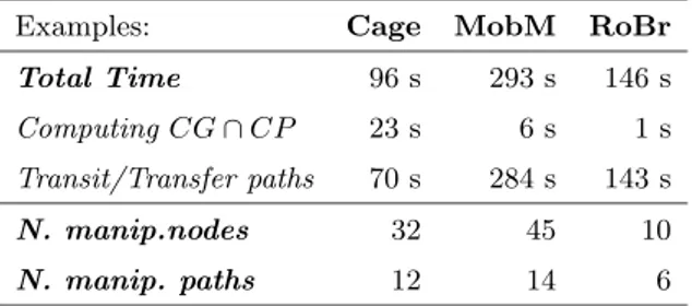
Table 1 shows for the three examples numerical results of the performance of the algorithm. All examples were solved after less than five minutes of com-putation. One can also note that most of the computation time is spent for checking connections with transit and transfer paths; this shows the interest of the proposed approach which limits the number of such connection tests by first computing connected components inside CG∩ CP . Also, the use of the visibility technique is the reason for the small size of the manipulation
roadmaps; such small roadmaps also reduces the number of connections to be tested.
Table 1. Numerical results
Examples: Cage MobM RoBr Total Time 96 s 293 s 146 s Computing CG∩ CP 23 s 6 s 1 s Transit/Transfer paths 70 s 284 s 143 s N. manip.nodes 32 45 10 N. manip. paths 12 14 6
5
Conclusion
We have presented a new approach to manipulation planning. The power of the approach lies in the fact that it can deal with continuous grasps and placements. It relies on a structuring of the search space allowing to directly capture into a probabilistic roadmap the connectivity of the sub-manifolds that correspond to the places where transit paths and transfer path can be connected. This structuring allows us to design a manipulation planner that automatically generates inside continuous domains, the particular grasps and placements that make the problem solvable. Simulations results show the effectiveness of the approach for solving complex manipulation problems.
There remain several possible improvements, in particular in the way to interleave the construction of CG∩ CP with the connection of its connected components via transit or transfer paths. Also, our manipulation planner is currently restricted to a single movable object manipulated by a single robot. Considering the case of multiple movable objects and robots first requires studying the conditions under which the reduction property can be extended to such situations. We also begin to investigate an alternative approach [8] combining a symbolic task planning level with our planner for solving a higher level of problems complexity in presence of multiple objects and robots.
References
1. J.M. Ahuactzin, K.K. Gupta and E. Mazer. Manipulation planning for redun-dant robots: a practical approach. In Practical Motion Planning in Robotics, K.K. Gupta and A.P. Del Pobil (Eds), J. Wiley, 1998.
2. R. Alami, T. Sim´eon, J.P. Laumond, A geometrical Approach to planning Manipulation Tasks. The case of discrete placements and grasps.” In Fifth In-ternational Symposium on Robotics Research, 1989.
3. R. Alami, J.P. Laumond and T. Sim´eon. Two manipulation planning algorithms. In Algorithmic Foundations of Robotics (WAFR94), K. Goldberg et al (Eds), AK Peters, 1995.
4. J. Barraquand and J.C. Latombe. Robot motion planning: a distributed repre-sentation approach. In International Journal of Robotics Research, 10(6), 1991. 5. J. Barraquand and P. Ferbach. A penalty function method for constrained
motion planning. In IEEE Int. Conf. on Robotics and Automation, 1994. 6. P. Bessiere, J. Ahuactzin, T, El-Ghazali and E. Mazer. The “Ariane’s clew”
algorithm: Global planning with local methods. In IEEE Int. Conf. on Robots and Systems, 1993.
7. J. Cort´es, T. Sim´eon and J.P. Laumond. A Random Loop Generator for planning the motions of closed kinematic chains with PRM methods. In IEEE Int. Conf. on Robotics and Automation, 2002.
8. F. Gravot, R. Alami and T. Sim´eon. Playing with several roadmaps to solve manipulation problems. In IEEE Int. Conf. on Intelligent Robots and Systems, 2002.
9. L. Han and N. Amato. A kinematics-based probabilistic roadmap method for closed kinematic chains. In Algorithmic and Computational Robotics (WAFR00), B.R. Donald et al (Eds), AK Peters, 2001.
10. L. Kavraki and J.C. Latombe. Randomized preprocessing of configuration space for fast path planning. In IEEE Int. Conf. on Robotics and Automation, 1994.
11. Y. Koga and J.C. Latombe. Experiments in dual-arm manipulation planning. In IEEE Int. Conf. on Robotics and Automation, 1992.
12. Y. Koga and J.C. Latombe. On multi-arm manipulation planning. In IEEE Int. Conf. on Robotics and Automation, 1994.
13. J. Kuffner and S. Lavalle. RRT-Connect: an efficient approach to single-query path planning. In IEEE Int. Conf. on Robotics and Automation., 2000. 14. J.C. Latombe. Robot Motion Planning, Kluwer, 1991.
15. J.P. Laumond and R. Alami. A geometrical Approach to planning Manipulation Tasks in robotics. In LAAS Technical Report no 89261, 1989.
16. JP. Laumond, T. Sim´eon. Notes on visibility roadmaps for motion planning. In Algorithmic and Computational Robotics (WAFR00), B.R. Donald et al (Eds), AK Peters, 2001.
17. S. LaValle, J.H. Yakey, and L. Kavraki. A probabilistic roadmap approach for systems with closed kinematic chains. In IEEE Int. Conf. on Robotics and Automation, 1999.
18. Ch. Nielsen, L. Kavraki. A two-level fuzzy PRM for manipulation planning. In IEEE Int. Conf. on Intelligent Robots and Systems, 2000.
19. M. Overmars and P. ˇSvestka. A Probabilistic learning approach to motion planning. In Algorithmic Foundations of Robotics (WAFR94), K. Goldberg et al (Eds), AK Peters, 1995.
20. T. Sim´eon, J.P. Laumond and C. Nissoux. Visibility-based probabilistic roadmaps for motion planning. In Advanced Robotics Journal 14(6), 2000 (a short version appeared in IEEE IROS, 1999).
21. T. Sim´eon, JP. Laumond, C. van Geem and J. Cort´es. Computer Aided Motion: Move3D within MOLOG. In IEEE Int. Conf. on Robotics and Automation, 2001. 22. T. Sim´eon, J. Cort´es, A. Sahbani and J.P. Laumond. A Manipulation Planner for Pick and Place Operations under Continuous Grasps and Placements. In IEEE Int. Conf. on Robotics and Automation, 2002.
23. A. Sahbani, J. Cort´es, T. Sim´eon. A probabilistic algorithm for manipula-tion planning under continuous grasps and placements. In IEEE Int. Conf. on Intelligent Robots and Systems, 2002.