PAPER
Advanced LIGO
To cite this article: The LIGO Scientific Collaboration et al 2015 Class. Quantum Grav. 32 074001
View the article online for updates and enhancements.
Related content
Advanced Virgo: a second-generation interferometric gravitational wave detector
-LIGO: the Laser Interferometer Gravitational-Wave Observatory
-Advanced LIGO: the next generation of gravitational wave detectors
-Recent citations
Constraints from Gravitational-wave Detections of Binary Black Hole Mergers on the 12C(, )16O Rate
R. Farmer et al
-Combining post-circular and Padé approximations to compute Fourier domain templates for eccentric inspirals
Srishti Tiwari and Achamveedu Gopakumar
-Search for strongly lensed counterpart images of binary black hole mergers in the first two LIGO observing runs
Connor McIsaac et al
-Advanced LIGO
The LIGO Scienti
fic Collaboration, J Aasi
1, B P Abbott
1,
R Abbott
1, T Abbott
2, M R Abernathy
1, K Ackley
3, C Adams
4,
T Adams
5,6, P Addesso
7, R X Adhikari
1, V Adya
8, C Affeldt
8,
N Aggarwal
9, O D Aguiar
10, A Ain
11, P Ajith
12, A Alemic
13,
B Allen
14,15, D Amariutei
3, S B Anderson
1, W G Anderson
15,
K Arai
1, M C Araya
1, C Arceneaux
16, J S Areeda
17,
G Ashton
18, S Ast
19, S M Aston
4, P Aufmuth
19, C Aulbert
14,
B E Aylott
20, S Babak
21, P T Baker
22, S W Ballmer
13,
J C Barayoga
1, M Barbet
3, S Barclay
23, B C Barish
1,
D Barker
24, B Barr
23, L Barsotti
9, J Bartlett
24, M A Barton
24,
I Bartos
25, R Bassiri
26, J C Batch
24, C Baune
8, B Behnke
21,
A S Bell
23, C Bell
23, M Benacquista
27, J Bergman
24,
G Bergmann
8, C P L Berry
20, J Betzwieser
4, S Bhagwat
13,
R Bhandare
28, I A Bilenko
29, G Billingsley
1, J Birch
4,
S Biscans
9, C Biwer
13, J K Blackburn
1, L Blackburn
30,
C D Blair
31, D Blair
31, O Bock
14, T P Bodiya
9, P Bojtos
32,
C Bond
20, R Bork
1, M Born
8, Sukanta Bose
11,33, P R Brady
15,
V B Braginsky
29, J E Brau
34, D O Bridges
4, M Brinkmann
8,
A F Brooks
1, D A Brown
13, D D Brown
20, N M Brown
9,
S Buchman
26, A Buikema
9, A Buonanno
35, L Cadonati
36,
J Calderón Bustillo
37, J B Camp
30, K C Cannon
38, J Cao
39,
C D Capano
35, S Caride
40, S Caudill
15, M Cavaglià
16,
C Cepeda
1, R Chakraborty
1, T Chalermsongsak
1,
S J Chamberlin
15, S Chao
41, P Charlton
42, Y Chen
43,
H S Cho
44, M Cho
35, J H Chow
45, N Christensen
46, Q Chu
31,
S Chung
31, G Ciani
3, F Clara
24, J A Clark
36, C Collette
47,
L Cominsky
48, M Constancio Jr
10, D Cook
24, T R Corbitt
2,
N Cornish
22, A Corsi
49, C A Costa
10, M W Coughlin
46,
S Countryman
25, P Couvares
13, D M Coward
31, M J Cowart
4,
D C Coyne
1, R Coyne
49, K Craig
23, J D E Creighton
15,
T D Creighton
27, J Cripe
2, S G Crowder
50, A Cumming
23,
L Cunningham
23, C Cutler
43, K Dahl
8, T Dal Canton
14,
M Damjanic
8, S L Danilishin
31, K Danzmann
19,8, L Dartez
27,
I Dave
28, H Daveloza
27, G S Davies
23, E J Daw
51, D DeBra
26,
W Del Pozzo
20, T Denker
8, T Dent
14, V Dergachev
1,
R T DeRosa
2, R DeSalvo
7, S Dhurandhar
11, M D
ıaz
27,
I Di Palma
21, G Dojcinoski
52, E Dominguez
53, F Donovan
9,
K L Dooley
8, S Doravari
4, R Douglas
23, T P Downes
15,
Class. Quantum Grav. 32 (2015) 074001 (41pp) doi:10.1088/0264-9381/32/7/074001J C Driggers
1, Z Du
39, S Dwyer
24, T Eberle
8, T Edo
51,
M Edwards
5, M Edwards
46, A Ef
fler
2, H.-B Eggenstein
14,
P Ehrens
1, J Eichholz
3, S S Eikenberry
3, R Essick
9, T Etzel
1,
M Evans
9, T Evans
4, M Factourovich
25, S Fairhurst
5, X Fan
23,
Q Fang
31, B Farr
54, W M Farr
20, M Favata
52, M Fays
5,
H Fehrmann
14, M M Fejer
26, D Feldbaum
3,4, E C Ferreira
10,
R P Fisher
13, Z Frei
32, A Freise
20, R Frey
34, T T Fricke
8,
P Fritschel
9, V V Frolov
4, S Fuentes-Tapia
27, P Fulda
3,
M Fyffe
4, J R Gair
55, S Gaonkar
11, N Gehrels
30, L Á Gergely
56,
J A Giaime
4,2, K D Giardina
4, J Gleason
3, E Goetz
14, R Goetz
3,
L Gondan
32, G González
2, N Gordon
23, M L Gorodetsky
29,
S Gossan
43, S Goßler
8, C Gräf
23, P B Graff
30, A Grant
23,
S Gras
9, C Gray
24, R J S Greenhalgh
57, A M Gretarsson
58,
H Grote
8, S Grunewald
21, C J Guido
4, X Guo
39, K Gushwa
1,
E K Gustafson
1, R Gustafson
40, J Hacker
17, E D Hall
1,
G Hammond
23, M Hanke
8, J Hanks
24, C Hanna
59,
M D Hannam
5, J Hanson
4, T Hardwick
34,2, G M Harry
60,
I W Harry
21, M Hart
23, M T Hartman
3, C-J Haster
20,
K Haughian
23, S Hee
55, M Heintze
3,4, G Heinzel
8, M Hendry
23,
I S Heng
23, A W Heptonstall
1, M Heurs
8, M Hewitson
8,
S Hild
23, D Hoak
36, K A Hodge
1, S E Hollitt
61, K Holt
4,
P Hopkins
5, D J Hosken
61, J Hough
23, E Houston
23,
E J Howell
31, Y M Hu
23, E Huerta
62, B Hughey
58, S Husa
37,
S H Huttner
23, M Huynh
15, T Huynh-Dinh
4, A Idrisy
59,
N Indik
14, D R Ingram
24, R Inta
59, G Islas
17, J C Isler
13,
T Isogai
9, B R Iyer
63, K Izumi
24, M Jacobson
1, H Jang
64,
S Jawahar
65, Y Ji
39, F Jiménez-Forteza
37, W W Johnson
2,
D I Jones
18, R Jones
23, L Ju
31, K Haris
66, V Kalogera
54,
S Kandhasamy
16, G Kang
64, J B Kanner
1, E Katsavounidis
9,
W Katzman
4, H Kaufer
19, S Kaufer
19, T Kaur
31, K Kawabe
24,
F Kawazoe
8, G M Keiser
26, D Keitel
14, D B Kelley
13, W Kells
1,
D G Keppel
14, J S Key
27, A Khalaidovski
8, F Y Khalili
29,
E A Khazanov
67, C Kim
68,64, K Kim
69, N G Kim
64, N Kim
26,
Y.-M Kim
44, E J King
61, P J King
24, D L Kinzel
4, J S Kissel
24,
S Klimenko
3, J Kline
15, S Koehlenbeck
8, K Kokeyama
2,
V Kondrashov
1, M Korobko
8, W Z Korth
1, D B Kozak
1,
V Kringel
8, B Krishnan
14, C Krueger
19, G Kuehn
8, A Kumar
70,
P Kumar
13, L Kuo
41, M Landry
24, B Lantz
26, S Larson
54,
P D Lasky
71, A Lazzarini
1, C Lazzaro
36, J Le
54, P Leaci
21,
S Leavey
23, E O Lebigot
39, C H Lee
44, H K Lee
69, H M Lee
68,
J R Leong
8, Y Levin
72, B Levine
24, J Lewis
1, T G F Li
1,
K Libbrecht
1, A Libson
9, A C Lin
26, T B Littenberg
54,
N A Lockerbie
65, V Lockett
17, J Logue
23, A L Lombardi
36,
M Lormand
4, J Lough
14, M J Lubinski
24, H Lück
19,8,
A P Lundgren
14, R Lynch
9, Y Ma
31, J Macarthur
23,
T MacDonald
26, B Machenschalk
14, M MacInnis
9,
D M Macleod
2, F Magaña-Sandoval
13, R Magee
33,
M Mageswaran
1, C Maglione
53, K Mailand
1, I Mandel
20,
V Mandic
50, V Mangano
23, G L Mansell
45, S Márka
25,
Z Márka
25, A Markosyan
26, E Maros
1, I W Martin
23,
R M Martin
3, D Martynov
1, J N Marx
1, K Mason
9,
T J Massinger
13, F Matichard
9, L Matone
25, N Mavalvala
9,
N Mazumder
66, G Mazzolo
14, R McCarthy
24, D E McClelland
45,
S McCormick
4, S C McGuire
73, G McIntyre
1, J McIver
36,
K McLin
48, S McWilliams
62, G D Meadors
40, M Meinders
19,
A Melatos
71, G Mendell
24, R A Mercer
15, S Meshkov
1,
C Messenger
23, P M Meyers
50, H Miao
20, H Middleton
20,
E E Mikhailov
74, A Miller
75, J Miller
9, M Millhouse
22, J Ming
21,
S Mirshekari
76, C Mishra
12, S Mitra
11, V P Mitrofanov
29,
G Mitselmakher
3, R Mittleman
9, B Moe
15, S D Mohanty
27,
S R P Mohapatra
9, B Moore
52, D Moraru
24, G Moreno
24,
S R Morriss
27, K Mossavi
8, C M Mow-Lowry
8, C L Mueller
3,
G Mueller
3, S Mukherjee
27, A Mullavey
4, J Munch
61,
D Murphy
25, P G Murray
23, A Mytidis
3, T Nash
1, R K Nayak
77,
V Necula
3, K Nedkova
36, G Newton
23, T Nguyen
45,
A B Nielsen
14, S Nissanke
43, A H Nitz
13, D Nolting
4,
M E N Normandin
27, L K Nuttall
15, E Ochsner
15, J O
’Dell
57,
E Oelker
9, G H Ogin
78, J J Oh
79, S H Oh
79, F Ohme
5,
P Oppermann
8, R Oram
4, B O
’Reilly
4, W Ortega
53,
R O
’Shaughnessy
80, C Osthelder
1, C D Ott
43, D J Ottaway
61,
R S Ottens
3, H Overmier
4, B J Owen
59, C Padilla
17, A Pai
66,
S Pai
28, O Palashov
67, A Pal-Singh
8, H Pan
41, C Pankow
15,
F Pannarale
5, B C Pant
28, M A Papa
15,21, H Paris
26,
Z Patrick
26, M Pedraza
1, L Pekowsky
13, A Pele
24, S Penn
81,
A Perreca
13, M Phelps
1, V Pierro
7, I M Pinto
7, M Pitkin
23,
J Poeld
8, A Post
14, A Poteomkin
67, J Powell
23, J Prasad
11,
V Predoi
5, S Premachandra
72, T Prestegard
50, L R Price
1,
M Principe
7, S Privitera
1, R Prix
14, L Prokhorov
29,
O Puncken
27, M Pürrer
5, J Qin
31, V Quetschke
27, E Quintero
1,
G Quiroga
53, R Quitzow-James
34, F J Raab
24, D S Rabeling
45,
H Radkins
24, P Raffai
32, S Raja
28, G Rajalakshmi
82,
M Rakhmanov
27, K Ramirez
27, V Raymond
1, C M Reed
24,
S Reid
83, D H Reitze
1,3, O Reula
53, K Riles
40,
N A Robertson
1,23, R Robie
23, J G Rollins
1, V Roma
34,
J D Romano
27, G Romanov
74, J H Romie
4, S Rowan
23,
A Rüdiger
8, K Ryan
24, S Sachdev
1, T Sadecki
24,
L Sadeghian
15, M Saleem
66, F Salemi
14, L Sammut
71,
V Sandberg
24, J R Sanders
40, V Sannibale
1,
I Santiago-Prieto
23, B S Sathyaprakash
5, P R Saulson
13,
R Savage
24, A Sawadsky
19, J Scheuer
54, R Schilling
8,
P Schmidt
5,1, R Schnabel
8,84, R M S Scho
field
34,
E Schreiber
8, D Schuette
8, B F Schutz
5,21, J Scott
23,
S M Scott
45, D Sellers
4, A S Sengupta
85, A Sergeev
67,
G Serna
17, A Sevigny
24, D A Shaddock
45, M S Shahriar
54,
M Shaltev
14, Z Shao
1, B Shapiro
26, P Shawhan
35,
D H Shoemaker
9, T L Sidery
20, X Siemens
15, D Sigg
24,
A D Silva
10, D Simakov
8, A Singer
1, L Singer
1, R Singh
2,
A M Sintes
37, B J J Slagmolen
45, J R Smith
17, M R Smith
1,
R J E Smith
1, N D Smith-Lefebvre
1, E J Son
79, B Sorazu
23,
T Souradeep
11, A Staley
25, J Stebbins
26, M Steinke
8,
J Steinlechner
23, S Steinlechner
23, D Steinmeyer
8,
B C Stephens
15, S Steplewski
33, S Stevenson
20, R Stone
27,
K A Strain
23, S Strigin
29, R Sturani
76, A L Stuver
4,
T Z Summerscales
86, P J Sutton
5, M Szczepanczyk
58,
G Szeifert
32, D Talukder
34, D B Tanner
3, M Tápai
56,
S P Tarabrin
8, A Taracchini
35, R Taylor
1, G Tellez
27, T Theeg
8,
M P Thirugnanasambandam
1, M Thomas
4, P Thomas
24,
K A Thorne
4, K S Thorne
43, E Thrane
1, V Tiwari
3,
C Tomlinson
51, C V Torres
27, C I Torrie
1,23, G Traylor
4,
M Tse
9, D Tshilumba
47, D Ugolini
87, C S Unnikrishnan
82,
A L Urban
15, S A Usman
13, H Vahlbruch
19, G Vajente
1,
G Valdes
27, M Vallisneri
43, A A van Veggel
23, S Vass
1,
R Vaulin
9, A Vecchio
20, J Veitch
20, P J Veitch
61,
K Venkateswara
88, R Vincent-Finley
73, S Vitale
9, T Vo
24,
C Vorvick
24, W D Vousden
20, S P Vyatchanin
29, A R Wade
45,
L Wade
15, M Wade
15, M Walker
2, L Wallace
1, S Walsh
15,
H Wang
20, M Wang
20, X Wang
39, R L Ward
45, J Warner
24,
M Was
8, B Weaver
24, M Weinert
8, A J Weinstein
1, R Weiss
9,
T Welborn
4, L Wen
31, P Wessels
8, T Westphal
8, K Wette
14,
J T Whelan
80,14, S E Whitcomb
1, D J White
51, B F Whiting
3,
C Wilkinson
24, L Williams
3, R Williams
1, A R Williamson
5,
J L Willis
75, B Willke
19,8, M Wimmer
8, W Winkler
8, C C Wipf
9,
H Wittel
8, G Woan
23, J Worden
24, S Xie
47, J Yablon
54,
I Yakushin
4, W Yam
9, H Yamamoto
1, C C Yancey
35, Q Yang
39,
M Zanolin
58, Fan Zhang
9,39, L Zhang
1, M Zhang
74, Y Zhang
80,
C Zhao
31, M Zhou
54, X J Zhu
31, M E Zucker
9, S Zuraw
36and
J Zweizig
11
LIGO, California Institute of Technology, Pasadena, CA 91125, USA
2
Louisiana State University, Baton Rouge, LA 70803, USA
3
University of Florida, Gainesville, FL 32611, USA
4LIGO Livingston Observatory, Livingston, LA 70754, USA 5
Cardiff University, Cardiff, CF24 3AA, UK
6
Laboratoire d’ Annecy-le-Vieux de Physique des Particules (LAPP), Université de Savoie, CNRS/IN2P3, F-74941 Annecy-le-Vieux, France
7
University of Sannio at Benevento, I-82100 Benevento, Italy and INFN, Sezione di Napoli, I-80100 Napoli, Italy
8
Experimental Group, Albert-Einstein-Institut, Max-Planck-Institut für, Gravitationsphysik, D-30167 Hannover, Germany
9
LIGO, Massachusetts Institute of Technology, Cambridge, MA 02139, USA
10
Instituto Nacional de Pesquisas Espaciais, 12227-010 São José dos Campos, SP, Brazil
11
Inter-University Centre for Astronomy and Astrophysics, Pune 411007, India
12
International Centre for Theoretical Sciences, Tata Institute of Fundamental, Research, Bangalore 560012, India
13Syracuse University, Syracuse, NY 13244, USA 14
Data Analysis Group, Albert-Einstein-Institut, Max-Planck-Institut für, Gravitationsphysik, D-30167 Hannover, Germany
15University of Wisconsin–Milwaukee, Milwaukee, WI 53201, USA 16
The University of Mississippi, University, MS 38677, USA
17
California State University Fullerton, Fullerton, CA 92831, USA
18
University of Southampton, Southampton, SO17 1BJ, UK
19Leibniz Universität Hannover, D-30167 Hannover, Germany 20
University of Birmingham, Birmingham, B15 2TT, UK
21
Albert-Einstein-Institut, Max-Planck-Institut für Gravitationsphysik, D-14476 Golm, Germany
22
Montana State University, Bozeman, MT 59717, USA
23
SUPA, University of Glasgow, Glasgow, G12 8QQ, UK
24
LIGO Hanford Observatory, Richland, WA 99352, USA
25
Columbia University, New York, NY 10027, USA
26
Stanford University, Stanford, CA 94305, USA
27The University of Texas at Brownsville, Brownsville, TX 78520, USA 28
RRCAT, Indore, MP 452013, India
29
Faculty of Physics, Lomonosov Moscow State University, Moscow 119991, Russia
30
NASA/Goddard Space Flight Center, Greenbelt, MD 20771, USA
31
University of Western Australia, Crawley, WA 6009, Australia
32
MTA Eötvös University,‘Lendulet’ Astrophysics Research Group, Budapest 1117, Hungary
33
Washington State University, Pullman, WA 99164, USA
34
University of Oregon, Eugene, OR 97403, USA
35University of Maryland, College Park, MD 20742, USA 36
University of Massachusetts Amherst, Amherst, MA 01003, USA
37
Universitat de les Illes Balears—IEEC, E-07122 Palma de Mallorca, Spain
38
Canadian Institute for Theoretical Astrophysics, University of Toronto, Toronto, Ontario, M5S 3H8, Canada
39Tsinghua University, Beijing 100084, People’s Republic of China 40
University of Michigan, Ann Arbor, MI 48109, USA
41National Tsing Hua University, Hsinchu Taiwan 300 42
Charles Sturt University, Wagga Wagga, NSW 2678, Australia
43
Caltech-CaRT, Pasadena, CA 91125, USA
44
Pusan National University, Busan 609-735, Korea
45
Australian National University, Canberra, ACT 0200, Australia
46Carleton College, Northfield, MN 55057, USA 47
University of Brussels, Brussels 1050, Belgium
48
Sonoma State University, Rohnert Park, CA 94928, USA
49
Texas Tech University, Lubbock, TX 79409, USA
50University of Minnesota, Minneapolis, MN 55455, USA 51The University of Sheffield, Sheffield S10 2TN, UK
52
Montclair State University, Montclair, NJ 07043, USA
53
Argentinian Gravitational Wave Group, Cordoba Cordoba 5000, Argentina
54
Northwestern University, Evanston, IL 60208, USA
55
University of Cambridge, Cambridge, CB2 1TN, UK
56
University of Szeged, Dóm tér 9, Szeged 6720, Hungary
57
Rutherford Appleton Laboratory, HSIC, Chilton, Didcot, Oxon OX11 0QX, UK
58
Embry-Riddle Aeronautical University, Prescott, AZ 86301, USA
59
The Pennsylvania State University, University Park, PA 16802, USA
60
American University, Washington, DC 20016, USA
61
University of Adelaide, Adelaide, SA 5005, Australia
62West Virginia University, Morgantown, WV 26506, USA 63
Raman Research Institute, Bangalore, Karnataka 560080, India
64
Korea Institute of Science and Technology Information, Daejeon 305-806, Korea
65
SUPA, University of Strathclyde, Glasgow G1 1XQ, UK
66
IISER-TVM, CET Campus, Trivandrum, Kerala 695016, India
67
Institute of Applied Physics, Nizhny Novgorod 603950, Russia
68
Seoul National University, Seoul 151-742, Korea
69Hanyang University, Seoul 133-791, Korea 70
Institute for Plasma Research, Bhat, Gandhinagar 382428, India
71
The University of Melbourne, Parkville, VIC 3010, Australia
72
Monash University, Victoria 3800, Australia
73
Southern University and A&M College, Baton Rouge, LA 70813, USA
74
College of William and Mary, Williamsburg, VA 23187, USA
75
Abilene Christian University, Abilene, TX 79699, USA
76
Instituto de Física Tórica, University Estadual Paulista/ICTP South American Institute for Fundamental Research, São Paulo SP 01140-070, Brazil
77IISER-Kolkata, Mohanpur, West Bengal 741252, India 78
Whitman College, 280 Boyer Ave, Walla Walla, WA 9936, USA
79
National Institute for Mathematical Sciences, Daejeon 305-390, Korea
80
Rochester Institute of Technology, Rochester, NY 14623, USA
81
Hobart and William Smith Colleges, Geneva, NY 14456, USA
82
Tata Institute for Fundamental Research, Mumbai 400005, India
83
SUPA, University of the West of Scotland, Paisley, PA1 2BE, UK
84
Universität Hamburg, D-22761 Hamburg, Germany
85
Indian Institute of Technology, Gandhinagar Ahmedabad Gujarat 382424, India
86Andrews University, Berrien Springs, MI 49104, USA 87
Trinity University, San Antonio, TX 78212, USA
88
University of Washington, Seattle, WA 98195, USA E-mail:[email protected]
Received 11 November 2014, revised 12 December 2014 Accepted for publication 30 December 2014
Published 3 March 2015 Abstract
The Advanced LIGO gravitational wave detectors are second-generation instruments designed and built for the two LIGO observatories in Hanford, WA and Livingston, LA, USA. The two instruments are identical in design, and are specialized versions of a Michelson interferometer with 4 km long arms. As in Initial LIGO, Fabry–Perot cavities are used in the arms to increase the interaction time with a gravitational wave, and power recycling is used to
increase the effective laser power. Signal recycling has been added in Advanced LIGO to improve the frequency response. In the most sensitive frequency region around 100 Hz, the design strain sensitivity is a factor of 10 better than Initial LIGO. In addition, the low frequency end of the sensitivity band is moved from 40 Hz down to 10 Hz. All interferometer components have been replaced with improved technologies to achieve this sensitivity gain. Much better seismic isolation and test mass suspensions are responsible for the gains at lower frequencies. Higher laser power, larger test masses and improved mirror coatings lead to the improved sensitivity at mid and high frequencies. Data collecting runs with these new instruments are planned to begin in mid-2015.
Keywords: gravitational waves, interferometers, seismic isolation, optics
(Somefigures may appear in colour only in the online journal)
1. Introduction
From its inception, the LIGO project was planned to involve the development and operation of multiple generations of increasingly sensitive gravitational wave detectors. The Advanced LIGO detectors are the second generation of interferometers designed and built for the two observatories operated by the LIGO laboratory: one on the Hanford site in Washington state, and the other in Livingston Parish, Louisiana. The Initial LIGO detectors, constructed in the late 1990s, operated at design sensitivity in a continuous data-taking mode from November
2005 to September 2007 [1]. Subsequently, upgrades were made to the interferometer laser
sources and readout systems [2], which improved the strain sensitivity at the most sensitive frequencies by approximately 30%; the instrument root-mean-square (rms) strain noise reached an unprecedented level of 2 × 10⁻²²in a 100 Hz band. In this configuration, Enhanced LIGO collected data from July 2009 to October 2010. Although no gravitational wave signals were detected with Initial or Enhanced LIGO, they produced several interesting astrophysical results; representative examples are listed in [3].
Compared to Initial LIGO, Advanced LIGO is designed to provide a factor of 10 increase in strain sensitivity over a broad frequency band, and to extend the low end of the band to 10 Hz (from 40 Hz). As the probed volume of the universe scales as the cube of the strain sensitivity, this represents an enormous increase (of order 103x) in the number of potential astrophysical sources detectable by these instruments. At design sensitivity, Advanced LIGO is likely to detect dozens of compact binary coalescence sources per year [4].
Housed within the vacuum system and facilities built for Initial LIGO, Advanced LIGO completely replaces the interferometer components with new designs and technology. Each observatory hosts one Advanced LIGO interferometer with 4 km long arms. A third inter-ferometer (originally planned as a second detector at Hanford) is consigned for a planned later installation at a new, currently undetermined site in India. All three interferometers are intended to be identical in design and expected performance. The addition of the third site (India) will provide significantly better source localization for the Advanced LIGO network [5].
US National Science Foundation funding for the construction and installation of Advanced LIGO began in April 2008. Installation of the new hardware began in early 2011, and was completed for the Livingston detector (L1) in mid-2014; installation of the Hanford detector (H1) will be completed by the end of 2014.
2. Interferometer configuration and system design
The optical configuration of the Advanced LIGO interferometer is shown in figure1. The
basis of the design is a Michelson interferometer with a Fabry–Perot resonant cavity in each arm to build up the phase shift produced by an arm length change. Power recycling is another standard feature of such interferometers: the power recycling mirror (PRM) forms a resonant cavity between the laser source and the Michelson to increase the effective laser power.
With Advanced LIGO, signal recycling [6] has been added to the interferometer. The
signal recycling mirror (SRM) at the anti-symmetric output of the Michelson is used to effectively lower the arm cavityfinesse for gravitational wave signals and thereby maintain a broad detector frequency response. The choice of SRM transmission and tuning is discussed in the section3. In principle, signal recycling can also be used to create a narrowband mode of operation, with enhanced sensitivity at, e.g., a likely pulsar frequency, though with higher noise at other frequencies. Though there are no current plans for narrowband operation, this option may be implemented in the future.
Figure 1.Advanced LIGO optical configuration. ITM: input test mass; ETM: end test
mass; ERM: end reaction mass; CP: compensation plate; PRM: power recycling mirror; PR2/PR3: power recycling mirror 2/3; BS: 50/50 beam splitter; SRM: signal recycling mirror; SR2/SR3: signal recycling mirror 2/3; FI: Faraday isolator; φm: phase
modulator; PD: photodetector. The laser power numbers correspond to full-power operation. All of the components shown, except the laser and phase modulator, are mounted in the LIGO ultra-high vacuum system on seismically isolated platforms.
The top-level parameters of the interferometers are listed in table 1. The motivations behind these and other system design choices are described in this section. The various interferometer subsystems and components are described in section4.
2.1. Arm cavity design
With signal recycling, the quantum noise-limited strain sensitivity is in principle independent of the arm cavityfinesse, and depends only on the power stored in the arms; thus the choice of finesse is guided by other practical considerations. Higher arm cavity finesse carries the
benefits of lower laser power in the power recycling cavity and reduced coupling from the
vertex Michelson degree-of-freedom. Lowerfinesse reduces the sensitivity to optical loss and
noise in the signal recycling cavity. The arm cavity finesse of 450 represents a trade-off
between these effects.
In order to reduce test mass thermal noise, the beam size on the test masses is made as large as practical so that it averages over more of the mirror surface. The dominant noise mechanism here is mechanical loss in the dielectric mirror coatings, for which the dis-placement thermal noise scales inversely with beam diameter. This thermal noise reduction is balanced against increased aperture loss and decreased mode stability with larger beams. The slightly asymmetric design of the arm cavity takes advantage of the fact that the ITMs contribute less to thermal noise because their coatings are half as thick as on the ETMs.
Therefore the beam can be somewhat smaller on the ITMs—with negligible increase in
thermal noise—in order to limit aperture losses in the beam splitter and recycling cavities; the ETM beam size is maximized to reduce this thermal noise contribution. The resonator g parameter product for the arm cavity is g1g2= 0.83, which is approaching the stability limit of
g1g2→ 1. Lower thermal noise thus comes at the expense of greater sensitivity to angular
misalignment.
The specified mirror beam sizes can be achieved with either of two designs: a
nearly-planar cavity or a nearly-concentric one. The nearly-concentric design is preferred for its higher stability with high stored power operation when torques due to optical radiation pressure become significant. In this case, the torsional mode with the higher optical stiffness is statically stable, whereas it would be statically unstable for a near-planar design [7].
Table 1.Main parameters of the Advanced LIGO interferometers. PRC: power recy-cling cavity; SRC: signal recyrecy-cling cavity.
Parameter Value
Arm cavity length 3994.5 m Arm cavityfinesse 450
Laser type and wavelength Nd:YAG,λ = 1064 nm Input power, at PRM up to 125 W
Beam polarization linear, horizontal Test mass material Fused silica
Test mass size and mass 34 cm diam. × 20 cm, 40 kg Beam radius (1/e2), ITM/ETM 5.3 cm/6.2 cm
Radius of curvature, ITM/ETM 1934 m/2245 m Input mode cleaner length andfinesse 32.9 m (round trip), 500 Recycling cavity lengths, PRC/SRC 57.6 m/56.0 m
2.2. Recycling cavity design
Both the power recycling and signal recycling cavities are designed to be stable for the fundamental Gaussian modes they support. That is, the fundamental cavity mode accrues a
non-negligible Gouy phase in a one-way propagation through the cavity. The benefit of this
design (new in Advanced LIGO) is that both recycling cavities have well defined spatial
eigenmodes and transversal mode-spacings much greater than the linewidth of the cavities [8]. The modes become less sensitive to mirror imperfections, resulting in more efficient signal detection. The stable design results in the folded layout shown in figure1 for these cavities. Each of the six recycling cavity mirrors is a curved optic; they produce a one-way Gouy phase of 25 and 19 degrees in the power and signal recycling cavities, respectively, and transform the beam radius from 5.3 cm at the ITMs to 2.2 mm at the PRM, and 2.1 mm at the SRM.
2.3. Gravitational wave readout
Readout of the gravitational wave signal is accomplished using an output mode cleaner (OMC) in conjunction with homodyne, or dc detection. In this scheme, a local oscillatorfield is generated by offsetting the arm cavities slightly from their resonance (typically a few picometers), thereby pulling the anti-symmetric output slightly off the dark fringe [2]. The
OMC filters out non-TEM00 mode carrier power, and any power in radio-frequency (RF)
modulation sidebands, so that only the carrier TEM00mode is detected. This greatly reduces
the power that must be detected at the output. Homodyne readout is a significant departure
from the heterodyne readout used in Initial LIGO. Compared to heterodyne detection, it is less susceptible to a number of technical noise couplings, but its primary benefits lie in lower quantum noise [9] and compatibility with the future use of squeezed light [10].
2.4. High power effects
Several effects may hinder interferometer operation at high power and need to be considered in the design: optical distortion produced by thermal effects from absorbed power; optical torques that can significantly impact alignment stability; and parametric instabilities arising from coupling between test mass acoustic modes and higher-order optical modes of the arm cavities.
As mentioned above, the torque induced by radiation pressure becomes comparable to the mechanical restoring torque of the test mass suspension, and must be accounted for in the angular controls system. This problem is addressed in [11], where it is shown that the unstable alignment modes have very low frequency, and can be readily stabilized with a suitable controlfilter.
The dominant source of thermal distortion is thermal lensing in the ITM substrates due to
power absorbed in the ITM reflective coatings. Next in importance, at high power, coating
absorption in the ITMs and ETMs causes a non-negligible change in their radii of curvature through thermo-elastic distortion. The thermal compensation system, described in section4.6, is designed to compensate both of these effects. The compensation plates (CPs) shown in
figure1 allow some of the distortion correction to be applied to these elements, which are
more noise-tolerant than the ITMs. The use of ultra-low absorption fused silica for the ITMs, the BS, and the CPs ensures that power absorbed in the bulk is negligible compared to that absorbed in the test mass high reflectivity coatings.
Parametric acousto-optic couplings have the potential to lead to unstable build-up of such coupled, higher-order modes [12]. Unchecked, this could impose a limit on the power stored
in the arms. Uncertainties in the parameters relevant to the process prevent an exact calcu-lation of the situation. Instead, statistical analyses can indicate the probability of instability at
a given power level. The general conclusion of these analyses is that there may be 5–10
modes per test mass that could become unstable at full power [13]. One or more of several mitigation methods may thus need to be applied. The simplest is to use the thermal com-pensation actuators to slightly change the radius of curvature of one or more test masses; this would shift the eigen-frequency of the higher-order optical mode to avoid overlap with the corresponding acoustic mode. A second technique would be to actively damp any unstable acoustic modes. Each test mass is equipped with an electro-static actuator (see section4.4.2) that can be used to apply a damping feedback force at the acoustic mode frequencies. A third technique, still in the research phase, is to apply passive tuned dampers to the test mas-ses [14].
3. Strain sensitivity
The interferometer design noise floor is determined by the fundamental noise sources,
quantum noise and thermal noise. Thermal noise is determined by fixed parameters in the
interferometer, such as material properties and beam size. Quantum noise, on the other hand, depends on the readily variable input laser power, and the (less readily) changeable SRM transmission. Other noise sources, such as laser frequency or amplitude noise, photodetector dark noise, actuator noise, etc, are classified as ‘technical’ noises. Technical noises are controlled by design so that the equivalent strain noise of each source is no greater than 10% of the target strain sensitivity throughout the detection band (10–7000 Hz). As these noise sources are typically statistically independent, they add as a root-square-sum to the total; an
individual 10% noise source thus increases the noise floor by only 0.5%: (12+ 0.12)1/
2= 1.005. In any given small frequency band, an octave, e.g., there may be several technical
noise sources that reach or approach this level.
Figure 2.Principal noise terms for the nominal (high power, broadband) mode of operation of Advanced LIGO.
The projected strain noise spectrum for the nominal Advanced LIGO mode of operation
is shown infigure2. In the nominal mode, the input power at the PRM is 125 W, the SRM
transmission is 20%, and the signal recycling cavity has zero detuning. The individual noise terms are described in the following sections.
Beyond the strain noise spectrum, a standardfigure of merit for detector sensitivity is the distance to which the gravitational wave signal emitted by a binary neutron star (BNS) coalescence is detectable. The BNS range is defined as the volume- and orientation-averaged distance at which the coalescence of a pair of 1.4-solar mass neutron stars gives a matched filter signal-to-noise ratio of 8 in a single detector [15]. The BNS range for the strain noise
curve in figure2 is 190 Mpc.
3.1. Quantum noise
Quantum noise encompasses the effects of statistical fluctuations in detected photon arrival rate (shot noise) and radiation pressure due to photon numberfluctuations. Quantum noise is
calculated using the formulation of Buonanno and Chen [16]. We assume 75 ppm round-trip
loss in each arm cavity, and 10−3loss in the power recycling cavity, which leads to 5.2 kW of power at the beamsplitter and 750 kW of power in each arm cavity. A detection efficiency of 90% is assumed; this accounts forfinite transmission through the output Faraday isolator and
OMC, as well as photodetector quantum efficiency.
3.2. Test mass thermal noise
Coating Brownian noise is the dominant of the various test mass thermal noise terms. It arises from mechanical dissipation in the coatings, and is calculated according to [17]. The coating design and material parameters are described in section4.3. Coating thermo-optic noise arises from thermal dissipation in the coatings, producing noise via the thermoelastic and thermo-refractive coefficients of the coating materials. The two effects are calculated coherently, according to [18]. Mechanical loss in the bulk fused silica is responsible for the substrate Brownian noise term. Reference [19] provides the calculation for this term, using the bulk and surface loss model for fused silica found in [20].
3.3. Suspension thermal noise
Thermal noise in the test mass suspension is primarily due to loss in the fused silica fibres used in thefinal suspension stage. As described in the suspension design section4.4.2, these four glassfibres have a circular, but variable diameter cross-section: they are thin in the main (middle) section of thefibre, and about twice as thick near the ends. This geometry minimizes
thermal noise, while keeping thefibre violin mode frequency high (510 Hz fundamental) and
the vertical stretching mode frequency low (9 Hz). The thermal noise is calculated using a finite-element model of the last suspension stage, including loss terms for the bulk, the surface, and the thermoelastic components of the fibre material [21].
3.4. Gravity gradients
Seismic waves produce density perturbations in the earth close to the test masses, which in
turn produce fluctuating gravitational forces on the masses. This seismic gravity-gradient
noise is estimated using the transfer function formulation of [22], and a representative model for the seismic motion at an observatory site. The latter can be quite variable over time, and
gravity gradient noise is predicted to be several times higher than shown infigure2for some time periods [23].
Figure2also shows the strain noise from the transmission of seismic noise through the seismic isolation and suspension systems to the test masses (the‘seismic noise’ curve). Due to the large mechanical isolation, this noise is negligible above 11 Hz.
3.5. Residual gas noise
Residual gas in the 4 km long beam tubes will lead to statistical variations in the column density of gas particles in the beam path, producing fluctuations in the effective refractive index along the path. The resulting optical path length noise is modelled by calculating the
impulsive change in the cavity field’s phase as a molecule moves through the beam, and
integrating over the molecular velocity distribution [24]. The noise curve includes only the most dominant residual gas component, hydrogen, at a pressure of 4 × 10⁻⁷Pa.
Though not included in the figure2 noise curve, residual gas in the test mass vacuum
chambers will contribute some damping to the test mass suspension, potentially increasing the suspension thermal noise. This damping effect is increased by the relatively narrow gap
between the test mass and its suspended reaction mass—so-called proximity-enhanced gas
damping [25]. Gas damping noise is most significant in the 10–40 Hz band, where it falls very nearly as f−2.At an anticipated chamber pressure of7 ×10−7 pascals of H
2, the resulting
strain noise is5×10−24 Hz at 20 Hz—a factor of 3–4 below the interferometer strain noise
infigure2. To mitigate the effect, this gap is larger for the ITMs (20 mm) than the ETMs
(5 mm), since the former do not require as much electro-static actuation force. This noise term is not included infigure2because it will eventually be made negligible (i.e., another factor of 3 reduction), through some combination of lower chamber pressure, an increased gap for the ETMs, and possibly a more complicated (ring-like) geometry for the end reaction mas-ses (ERMs).
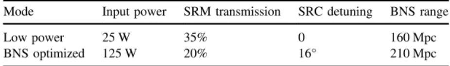
3.6. Other modes of operation
As mentioned above, the laser input power and the signal recycling cavity parameters can be varied to implement different modes of operation than the nominal mode represented by
figure 2. We illustrate the potential parameter space with two particular alternate
inter-ferometer modes: a mode optimized for low input power; a mode optimized for BNS detection. The low power mode is of interest because achieving operation at full power is likely to take extended commissioning time—as mentioned in section2.4, thermal effects and parametric instabilities will need to be mitigated at full power. Early operations and obser-vation runs will therefore be carried out at reduced power. The BNS optimized mode shows the potential sensitivity to this particular source, and the corresponding trade-off in broadband sensitivity. Table 2gives the parameters for the two modes, andfigure3shows their strain noise spectra.
Table 2.Interferometer parameters for two alternate modes of operation.
Mode Input power SRM transmission SRC detuning BNS range
Low power 25 W 35% 0 160 Mpc
4. Detector subsystems 4.1. Laser source
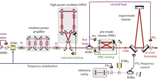
The interferometer employs a multi-stage Nd:YAG laser that can supply up to 180 W at the laser system output. The pre-stabilized laser (PSL) system [26] consists of this laser light source, and control systems that stabilize the laser in frequency, beam direction, and intensity.
Figure 3.Advanced LIGO strain noise spectrum for the modes defined in table2, and for the nominal sensitivity shown infigure2. The feature at 500 Hz is the (unresolved) fundamental vibrational mode of the test mass suspensionfibres.
Figure 4. Schematic of the pre-stabilized laser system. The input mode cleaner is discussed in section 4.2. AOM: acousto-optic modulator; EOM: electro-optic modulator; FI: Faraday isolator; PD: photodetector.
The laser was developed and supplied by the Max Planck Albert Einstein Institute in col-laboration with Laser Zentrum Hannover e.V. A schematic drawing of the PSL is shown in figure4.
The laser comprises three stages. Thefirst stage is a commercial non-planar ring-oscil-lator (NPRO) manufactured by InnoLight GmbH. The second stage (medium power ampli-fier) is a single-pass amplifier that boosts the NPRO power to 35 W, and the third stage is an injection-locked ring oscillator with a maximum output power of about 220 W. All stages are pumped by laser diodes; the pump diodes for the second and third stages arefibre coupled and located far from the laser table for easier management of power and cooling. The system may
be configured for 35 W output by using the NPRO and medium power stages only, bypassing
the high power oscillator; this configuration will be in the early operations of
Advanced LIGO.
The source laser is passed through the pre-mode cleaner (PMC). The PMC is a bow-tie cavity (2 m round trip length) designed to strip higher-order modes from the beam, to reduce beam jitter (amplitude reduction factor for TEM01/TEM10modes of 63), and to provide
low-passfiltering for RF intensity fluctuations (cavity pole at 560 kHz).
Intensity stabilization requirements are quite stringent across the gravitational wave band. At full laser power, radiation pressure effects in the arm cavities lead to a residual intensity noise specification of 2 × 10⁻⁹Hz−1/2 at 10 Hz, at the input to the PRM. This stability is
achieved through cascaded sensors and feedback loops. Thefirst sensor measures the power
in the PMC mode, and the second sensor samples light transmitted through the input mode cleaner. To ensure that an accurate low-noise measurement is made, the second sensor profits from the beam stability post-mode-cleaner, is in vacuum, and consists of multiple diodes used at low power. An acousto-optic modulator (AOM1) is the actuator for this control loop.
The initial frequency stabilization of the laser is performed in the PSL by locking its
frequency to an isolated, high-finesse reference cavity (bandwidth of 77 kHz) using the
standard reflection locking technique. Three actuators are used to provide wide bandwidth
and large dynamic range: a PZT attached to the NPRO crystal; an electro-optic modulator
(EOM1)—used as a broadband, phase corrector—between the NPRO and medium power
Figure 5.Mode scan of the high power laser used on the L1 interferometer. Close to 95% of the power is in the TEM00mode (located at 0 and 1 on the horizontal axis).
amplifier; and the NPRO crystal temperature for slow, wide-range control. The servo band-width is 400 kHz. The beam used for this frequency pre-stabilization is taken after the PMC, and is double-passed through an AOM before being sent to the reference cavity. This AOM is driven by a voltage-controlled oscillator to provide laser frequency actuation (1 MHz range, 100 kHz bandwidth) for subsequent stages of stabilization.
Figure 5 shows a mode scan of the L1 high-power laser beam when operating at full
output power. The total power in higher-order (non-TEM00) modes is 5.3% of the total. This
is measured before the PMC, which will filter out this high-order mode content.
4.2. Input optics
The input optics subsystem (IO) accepts the light from the PSL, stabilizes and conditions it, and performs matching and pointing into the main interferometer core optics. A schematic view is shown infigure6. The optical efficiency of the IO, from the PSL output to the PRM, is designed to be at least 75%. The system can be broken down into the following functional units.
4.2.1. RF modulation. RF phase modulation is impressed on the beam and used for global sensing of the interferometer (see section4.8) and for sensing of the IMC. Three modulation frequencies are applied, all with small modulation depth: 9 MHz and 45 MHz for the main interferometer sensing; 24 MHz for IMC sensing. The modulator must exhibit good phase modulation efficiency, low residual amplitude modulation, and negligible thermal lensing up
to a beam power of 165 W [27]. The EOM uses a 40 mm long, 4 × 4 mm cross-section,
wedged rubidium titanyl phosphate crystal as the electro-optic material. Three pairs of electrodes are used to apply the three modulation frequencies to the crystal.
4.2.2. Input mode cleaner. The IMC supplies a key function of the IO system: to stabilize the PSL beam in position and mode content, and to provide a high-quality laser frequency reference. The beam pointing stability at the input to the PRM, expressed relative to the beam
radius and beam divergence angle, must be <1 × 10⁻⁸Hz−1/2 at 100 Hz. The frequency
stability at the IMC output must be <1 × 10⁻³Hz/Hz1/2at 100 Hz.
The IMC is a three-mirror ring cavity used in transmission. Each mirror is suspended in a
triple pendulum suspension with metal wire loops (see section 4.4) to provide vibration
isolation and acceptable thermal noise. The IMC finesse is 500, the round trip length is
Figure 6.Schematic of the input optics components. IFI: input Faraday isolator. P: periscope. IMn: input mirror 1–4.
32.9 m, and the linewidth is 18 kHz. The 24 MHz phase modulation sidebands are used both for reflection locking and wavefront-sensor alignment control of the IMC. Additionally, the IMC is used as a frequency actuator for thefinal level of frequency stabilization to the long arm cavities.
4.2.3. Faraday isolator. An in-vacuum Faraday isolator is mounted between the IMC output
and the PRM; the isolator extracts the beam reflected from the interferometer and prevents
this beam from creating parasitic interference in the input chain. The isolator must deliver a minimum of 30 dB of isolation up to 125 W of laser power. To compensate thermally induced birefringence, the isolator uses two terbium gallium garnet crystals for Faraday rotation, with a quartz rotator in between. Compensation of thermal lensing is achieved by incorporating a negative dn/dT material (deuterated potassium dihydrogen phosphate) in the assembly [28]. 4.2.4. Mode matching. The IMC output beam must be matched to the interferometer mode,
with a targeted efficiency of 95% or better. This mode matching is accomplished with two
curved mirrors, in combination with twoflat mirrors used for beam routing. All four of these
reflective optics are mounted in single stage suspensions for vibration isolation; the
suspensions also have actuators to provide remote steering capability (see section 4.4). 4.3. Core optics
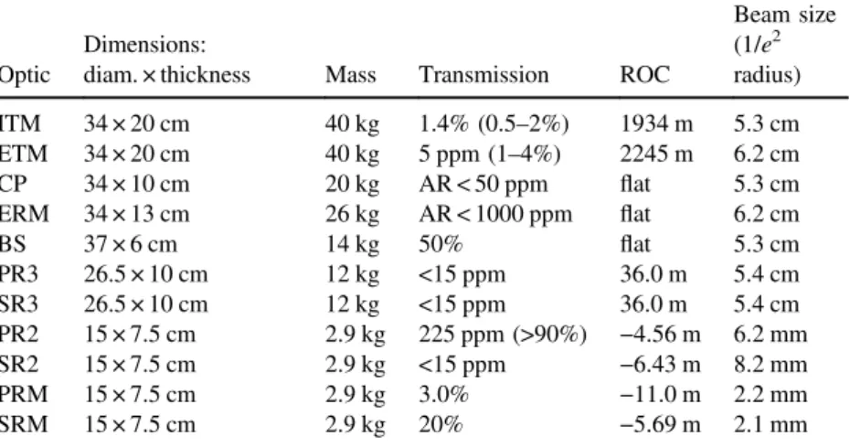
The‘core optics’ are central to the interferometer performance. For each interferometer they include (see table3):
• Two input and two end test masses which form the Fabry–Perot arms. • A 50/50 beamsplitter at the vertex of the Michelson interferometer.
• Two CPs that serve as actuation reaction masses for the input test masses, and to which thermal compensation can be applied.
• Two actuation reaction masses for the end test masses.
Table 3.Parameters of the core optics. ETM/ITM: end/input test mass; CP: compen-sation plate; ERM: end reaction mass; BS: beam splitter; PR3/2: power recycling mirror 3/2; SR3/2: signal recycling mirror 3/2; PRM/SRM: power/signal recycling mirror. ROC: radius of curvature; AR: anti-reflection. Transmission values are at 1064 nm, except for those in parentheses, which are for 532 nm.
Optic
Dimensions:
diam. × thickness Mass Transmission ROC
Beam size (1/e2 radius) ITM 34 × 20 cm 40 kg 1.4% (0.5–2%) 1934 m 5.3 cm ETM 34 × 20 cm 40 kg 5 ppm (1–4%) 2245 m 6.2 cm CP 34 × 10 cm 20 kg AR < 50 ppm flat 5.3 cm ERM 34 × 13 cm 26 kg AR < 1000 ppm flat 6.2 cm BS 37 × 6 cm 14 kg 50% flat 5.3 cm PR3 26.5 × 10 cm 12 kg <15 ppm 36.0 m 5.4 cm SR3 26.5 × 10 cm 12 kg <15 ppm 36.0 m 5.4 cm PR2 15 × 7.5 cm 2.9 kg 225 ppm (>90%) −4.56 m 6.2 mm SR2 15 × 7.5 cm 2.9 kg <15 ppm −6.43 m 8.2 mm PRM 15 × 7.5 cm 2.9 kg 3.0% −11.0 m 2.2 mm SRM 15 × 7.5 cm 2.9 kg 20% −5.69 m 2.1 mm
• Four reflective curved mirrors in the signal and power recycling cavities. • Signal and PRMs.
All the core optics are made with fused silica substrates. Their fabrication involves three components: material type; substrate polishing; and coatings. The test masses naturally have the most stringent requirements for all three aspects.
The fused silica material used for the input test masses, the CPs, and the beamsplitter is Heraeus Suprasil 3001. This is an ultra-low absorption grade, with absorption at 1064 nm of <0.2 ppm cm−1. The material also has a low level of inhomogeneity and low mechanical loss. The material for the other core optics is less critical, and less expensive grades of fused silica are used (ETMs use Heraeus Suprasil 312).
The surface quality required of the polishing is determined largely by the targeted round-trip optical loss in the arm cavities. For a given input laser power, this loss determines the achievable stored power in the arms, and thus the quantum noise level of the interferometer. For Advanced LIGO the arm round-trip loss goal is set at 75 ppm. This would allow a total
arm cavity stored power (both arms) of up to: 1/75 ppm = 1.3 × 10⁴times the input power.
Table4lists the test mass substrate polishing requirements, as well as typical achieved levels. The substrates for the large core optics are produced by a combination of super-polishing for small scale smoothness, followed by ion-beam milling to achieve the large scale uniformity. All the optical coatings are ion-beam sputtered, multi-layer dielectrics. The test masses are coated by Laboratoire Matériaux Avancés (LMA, Lyon, France); all other large core optics are coated by CSIRO (Sydney, Australia). The critical properties of the coating materials are low optical absorption, low scatter, and low mechanical loss (particularly for the test masses). For all optics other than the test masses, the coatings are traditional alternating layers of silicon-dioxide and tantalum pentoxide, each of ¼-wavelength optical thickness. For
the test masses, the TaO5 is doped with 25% titanium dioxide, a recipe that reduces the
mechanical loss by about 40% [30]. In addition, the layer thicknesses are altered: the SiO2
layers are a little thicker and the Ti–TaO5layers are a little thinner than a ¼-wavelength. This
design not only achieves the transmission specifications at 532 nm, but it also gives a further,
Table 4.Polishing specifications and results for the test masses.
Surface error, central 160 mm diam., power and astigmatism removed, rms
> 1 mm−1 1–750 mm−1 Radius of curvature spread Specification < 0.3 nm < 0.16 nm −5, +10 m
Actual 0.08–0.23 nm 0.07–0.14 nm −1.5, +1 m
Table 5.Test mass coating material parameters used to calculate coating thermal noise (i.e., this represents our model of the coating).
Parameter Low-index: silica High-index: tantala Mechanical loss 4 × 10⁻⁵[31] 2.3 × 10⁻⁴[32] Index of refraction 1.45 2.0654
dn/dT 8 × 10⁻⁶K−1 1.4 × 10⁻⁵K−1[32] Thermal expansion coefficient 5.1 × 10⁻⁷K−1 3.6 × 10⁻⁶K−1[32] Young’s modulus 72 GPa [31] 140 GPa [32] Layer optical thickness, ITM/ETM 0.308λ/0.27 λ 0.192λ/0.23 λ
modest reduction in thermal noise because less Ti–TaO5is used; see table 5for the coating
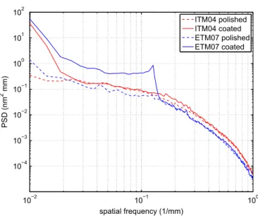
material parameters that are used to calculate the thermal noise curve shown in figure2. All core optics are characterized with high precision metrology, before and after coating.
As an example,figure7shows power spectra of the measured phase maps of the test masses
used in one arm of the L1 interferometer. The coating contributes additional non-uniformity greater than the substrate at larger spatial scales. Comparing the phase map residuals over the central 160 mm diameter, after subtracting tilt and power, gives:
• ETM substrate: 0.18 nm rms coated: 0.69 nm rms • ITM substrate: 0.15 nm rms coated: 0.31 nm rms
Optical simulations of an arm cavity formed with these two test mass mirrors predict a total round trip loss of about 44 ppm (20 ppm due to distortions captured in the phasemap, 20 ppm due to smaller scale roughness that causes wider angle scatter, 4 ppm from ETM transmission). This is well within the goal of 75 ppm, though particulate contamination of installed optics can contribute a few tens of ppm additional loss.
Though coating absorption is a negligible component of the total loss, it is critical for higher power operation (see section4.6). Absorption in the test mass high-reflectivity
coat-ings is specified at less than 0.5 ppm, and actual coatings show measured absorption of
0.2–0.4 ppm. Other coatings are specified to have absorption less than 1 ppm.
The test mass coatings delivered to date meet many of their challenging requirements such as absorption and scattering, but some of the properties are not ideal:
• For the ETMs, a systematic error in the layer thicknesses left the 1064 nm transmission in spec, but caused the 532 nm transmission to be larger than desired by an order of magnitude. This has made the (ALS) system described in section 4.8.4 much more challenging.
• Features of the coating planetary system produce a ∼1 nm peak-to-peak thickness ripple, with an 8 mm period, in the outer regions of the mirror. This is the peak seen in the
Figure 7.Power spectra of the surface maps, coated and un-coated, for the ITM and ETM used in one arm of the L1 interferometer.
ETM07 coated curve infigure7. This surface ripple scatters light out of the arm cavity; the optical loss is not significant (6 ppm), but the scattered light impinges on the beam tube baffles and can cause excess phase noise (see section4.7).
• Spherical aberration of the ETM coatings is 2–3 times higher than the specification of 0.5 nm. This will alter slightly the shape of the cavity fundamental mode compared to an
ideal Gaussian TEM00mode. However, the aberration is very similar from ETM to ETM,
so the arm cavity modes are well matched and this defect does produce significant loss. • The anti-reflection coatings on the ITMs have 2–3 times higher reflectivity than the specification of 50 ppm. Though not significant in terms of loss, the higher AR produces higher power ghost beams that may need better baffling to control scattered light noise (see section 4.7).
4.4. Suspensions
All of the primary in-vacuum interferometer optical components (all those depicted in figure1, with the exception of the input Faraday isolator) are suspended by pendulum systems of varying designs. These suspension systems provide passive isolation from motion of the seismically isolated optics tables in all degrees of freedom and acceptable thermal noise. The suspensions also provide low noise actuation capability, used to align and position the optics based on interferometer sensing and control signals.
4.4.1. Requirements. The suspension designs employed for each optical element depend upon the performance requirements and physical constraints, as listed in table6. Most of the suspensions employ multiple pendulum and vertical isolation stages.
4.4.2. Design description. The most challenging design is the quadruple pendulum
suspension for the test masses [29]. Each of these suspensions is comprised of two
adjacent chains, each chain having four masses suspended from one another, as shown in
figure 8. The main chain includes the test mass optic as the lowest mass. The adjacent,
reaction chain provides an isolated set of masses for force reaction. The bottom mass in the reaction chain is the CP optic in the case of an ITM suspension, and the ERM in the case of an ETM suspension. A structure surrounds and cages the suspended masses and mounts to the seismically isolated optics table.
Vibration isolation for the test mass is accomplished with a 4-stage pendulum and 3 stages of cantilevered blade springs, providing isolation in all six degrees-of-freedom (DoF) above approximately 1 Hz. The suspension is designed to couple 22 of the 24 quasi-rigid body modes (all but the 2 highest frequency) of each isolation chain so that they are observable and controllable at the top mass (4 wires between masses to couple pitch and roll modes; non-vertical wires to couple pendulum modes). The blade springs are made of maraging steel to minimize noise resulting from discrete dislocation movements associated with creep under load [33].
For each chain, all the quadruple suspension rigid body modes below 9 Hz can be actively damped from the top stage. Sensing for this local damping is accomplished with integral optical shadow sensors [34], or with independent optical lever sensors. The shadow sensors are collocated with the suspension actuators and have a noise level of 3 × 10⁻¹⁰m√Hz−1at 1 Hz.
Force actuation on the upper three masses is accomplished with coil/magnet actuators [34]. Six degree-of-freedom actuation is provided at the top mass of each chain, by reacting against the suspension structure. These actuators are used for the local damping of 22 modes (each chain). The next two masses can be actuated in the pitch, yaw and piston directions, by applying forces between adjacent suspended masses. These stages are used for global interferometer control. Low noise current drive electronics, combined with the passive filtering of the suspension, limit the effect of actuation noise at the test mass.
Direct low-noise, high-bandwidth actuation on the test mass optic is accomplished with
electro-static actuation [35]. The CP and ERM each have an annular pattern of gold
electrodes, deposited on the face adjacent to the test mass, just outside the central optical aperture. The pattern is separated into four quadrants, which enables actuation in pitch, yaw and piston. The force coefficient is highly dependent on the separation between the test mass
Table 6.Suspension types. Auxiliary suspensions are for optical pick-off beams, beam steering and mode matching.
Optical component Vertical isolation stages Pendulum stages Final stage fibre type Longitudinal noise requirement @ 10 Hz (m√Hz−1) Test masses (ITM, ETM) 3 4 Fused
silica
1 × 10⁻¹⁹
Beamsplitter (BS) 2 3 Steel wire 6 × 10⁻¹⁸ Recycling cavity optics 2 3 Steel wire 1 × 10⁻¹⁷ Input mode cleaner (IMC) optics 2 3 Steel wire 3 × 10⁻¹⁵ Output mode cleaner
(OMC) assy
2 2 Steel wire 1 × 10⁻¹³
ETM transmission monitor 2 2 Steel wire 2 × 10⁻¹² Auxiliary suspensions 1 1 Steel wire 2 × 10⁻¹¹
and its reaction mass. The ETM–ERM separation is 5 mm, which provides a maximum force
of about 200μN using a high-voltage driver. Less actuation is needed on the ITMs, so the
CP–ITM gap is increased to 20 mm to mitigate the effect of squeezed film damping [25].
The test mass and the penultimate mass are a monolithic fused silica assembly, designed
to minimize thermal noise [36]. Machined fused silica elements (‘ears’) are
hydroxide-catalysis (silicate) bonded to flats polished onto the sides of the test mass and penultimate mass. Custom drawn fused silicafibres are annealed and welded to the fused silica ears with a CO2laser system [37]. The shape of thefibres is designed to minimize thermal noise (400 μm
dia. by 596 mm long with 800μm dia. by 20 mm long ends), while achieving a low
suspension vertical‘bounce’ mode (9 Hz, below band) and high first violin mode frequency
(510 Hz, above the instrument’s most sensitive frequency range). The fibre stress (800 MPa) is well below the immediate, static, breaking strength (5 GPa).
The other suspension types employ the same basic key principles as the test mass quadruple suspensions, except for using steel wire in the final stage.
4.4.3. Performance. The transfer functions (actuation to response) in all degrees of freedom
in general match very well the model for the test mass suspension;figure9shows one such
comparison. Furthermore, the transfer functions are well matched from suspension to suspension, so that very small, if any, parameter value changes are required for the control filters of the multi-input, multi-output control system.
The thermal noise performance of the suspension cannot be verified until the
interferometer is fully commissioned and operating at design sensitivity. The displacement thermal noise spectrum for the monolithic stage is made up of quadrature sum of
contributions from the horizontal pendulum mode, the vertical mode (with a vertical–
horizontal cross-coupling assumed of 0.1%), thefirst violin mode and the loss associated with the silicate bonded ears. The as-installed quality factor (Q) of the first violin modes of the
fibres has been measured to be 1.1–1.6 × 10⁹, which is about a factor of 2 higher than
anticipated from prototype testing [36], and is consistent with the anticipated level of thermal noise.
4.5. Seismic isolation
The general arrangement of the seismic isolation system and its relationship to the vacuum system and the suspension systems is illustrated infigure10, where a cut-away view of one of the test mass vacuum chambers is also shown.
4.5.1. Requirements. The motion of the detector components, especially the interferometer optics, must be limited to very small amplitudes. The conceptual approach for seismic
isolation is to provide multiple stages of isolation, as depicted in figure 11. The stages
topologically closest to the ground are referred to as the seismic isolation system; they provide coarse alignment, and employ both active and passive isolation to deal with the highest amplitude of motion. An optics table provides the interface between the seismic isolation system and the subsequent suspension system. The optics tables in the smaller (HAM) vacuum chambers are 1.9 m by 1.7 m; the downward-facing optics tables in the larger
(BSC) vacuum chambers are 1.9 m diameter. The limits to optics table motion (table7) are
derived from the allowed motion for the interferometer optics using the passive isolation performance of the suspension systems.
4.5.2. Design description. Thefirst measure taken to reduce ground motion was to site the
observatories in seismically quiet locations [38]. The observatory facilities were then
designed to limit vibration source amplitudes (e.g., the chiller plant for the HVAC system is remote from the experimental hall). Additional isolation from the already seismically quiet ground motion is provided by the seismic isolation and suspension subsystems.
All in-vacuum interferometer elements are mounted on seismically isolated optics tables (with the exception of some stray light control elements). The typical seismic isolation system consists of two or three stages of isolation (figure11). Thefirst stage is accomplished with the Hydraulic External Pre-Isolator (HEPI) system, external to the vacuum system. The next one or two stages are referred to as the Internal Seismic Isolation (ISI) system and are contained within the vacuum system. The test mass, beamsplitter and transmission monitor suspensions are supported by inverted optics tables which have two in-vacuum stages, housed in the BSC chambers. All other interferometer elements are supported by upright optics tables connected to one-stage ISI systems, housed in smaller (HAM) vacuum chambers.
The in-vacuum payload is supported by a structure that penetrates the vacuum chamber at four locations, through welded bellows. Each of these four points is supported by a HEPI assembly; each HEPI system supports a total isolated mass of 6400 kg. HEPI employs custom
designed, laminarflow, quiet hydraulic actuators (8 per vacuum chamber) in a low frequency
(0.1–10 Hz), six degree-of-freedom active isolation and alignment system. The actuators
employ servo-valves in a hydraulic Wheatstone bridge configuration to control deflection of a diaphragm by differential pressure. For sensors, HEPI uses a blend of geophones and inductive position sensors. In addition, a ground seismometer provides a signal for feed-forward correction. The HEPI system was deployed for the Initial LIGO L1 interferometer
[39] and remains essentially the same for Advanced LIGO.
The ISI [40] consists of three stages (each a stiff mechanical structure) that are suspended and sprung in sequence: stage 0 is the support structure connected to the HEPI frame; stage 1 is suspended and sprung from stage 0; stage 2 is suspended and sprung from stage 1. The
Figure 9.Transfer functions from longitudinal force to longitudinal position of the top mass for the four test mass suspensions at LLO. Active local damping is engaged for these measurements; the suspension model curve shows good agreement with the data.
elastic, structural modes of stages 1 and 2 are designed to be >150 Hz in order to keep them
high above the upper unity gain frequency (∼40 Hz) of the control system. The stage 2
structure includes the optics table upon which payload elements, such as the suspensions, are attached. Each suspended stage is supported at three points by a rod withflexural pivot ends, which are in turn supported by cantilevered blade springs. The springs provide vertical
isolation and the flexure rods provide horizontal isolation. They are both made of high
strength maraging steel in order to reduce noise resulting from discrete dislocation movement events associated with creep under load. The springs andflexures allow control in all six rigid body DoF of each stage, through the use of electromagnetic force actuation between the stages. Passive isolation from base (stage 0) motion is achieved at frequencies above the rigid body frequencies of these stages.
Stage 1 of the ISI is instrumented with 6 capacitive position sensors (MicroSense), 3 three-axis seismometers (Nanometric Trillium T240) and 6 geophones (Sercel L4C). Stage 2 is instrumented with six capacitive position sensors (MicroSense) and six geophones (Geotech GS13). The single-axis sensors are equally divided into horizontal and vertical directions. All of the inertial sensors are sealed in vacuum-tight canisters. The 12
electromagnetic actuators (6 between stages 0–1 and 6 between stages 1–2) are equally
split between vertical and horizontal orientations, and are a custom, ultra-high vacuum compatible design.
Figure 11.Seismic isolation for the test mass optic.
Table 7.Seismic isolation performance requirements for the BSC chamber, 3 stage systems.
Requirement Value
Payload mass 800 kg
Positioning/alignment range ±1 mm ±0.25 mrad Tidal and microseismic actuation range ±100μm
Isolation (3 translations) 2 × 10⁻⁷m/√Hz @ 0.2 Hz 1 × 10⁻¹¹m/√Hz @ 1 Hz 2 × 10⁻¹³m/√Hz @ 10 Hz 3 × 10⁻¹⁴m/√Hz @ > 30 Hz Isolation (3 rotations) <10−8rad rms, for 1 < f < 30 Hz