HAL Id: hal-02176472
https://hal.archives-ouvertes.fr/hal-02176472
Submitted on 7 Jul 2020
HAL is a multi-disciplinary open access
archive for the deposit and dissemination of
sci-entific research documents, whether they are
pub-lished or not. The documents may come from
teaching and research institutions in France or
abroad, or from public or private research centers.
L’archive ouverte pluridisciplinaire HAL, est
destinée au dépôt et à la diffusion de documents
scientifiques de niveau recherche, publiés ou non,
émanant des établissements d’enseignement et de
recherche français ou étrangers, des laboratoires
publics ou privés.
An Efficient DOA Estimation Method for Co-prime
Linear Arrays
Xiao Yang, Yanping Wang, Pascal Chargé, Yuehua Ding
To cite this version:
Xiao Yang, Yanping Wang, Pascal Chargé, Yuehua Ding. An Efficient DOA Estimation Method
for Co-prime Linear Arrays.
IEEE Access, IEEE, 2019, 7, pp.90874-90881.
An Efficient DOA Estimation Method
for Co-Prime Linear Arrays
XIAO YANG 1, YIDE WANG 1, (Senior Member, IEEE), PASCAL CHARGÉ 1, AND YUEHUA DING 2
1Institut d’Electronique et Télécommunications de Rennes (IETR), Université de Nantes, 44306 Nantes, France 2School of Electronic and Information Engineering, South China University of Technology, Guangzhou 510641, China
Corresponding author: Yuehua Ding ([email protected])
This work was supported in part by the China Scholarship Council under Grant 201708440322, in part by the National Natural Science Foundation of China under Grant 61673260, in part by the Guangzhou Science and Technology Program under Grant 201807010071, in part by the funds of Central Universities under Grant 2018ZD09, and in part by the 2017–2019 Sino-French CAI Yuanpei Program.
ABSTRACT Direction-of-arrival (DOA) estimation with a co-prime linear array, composed of two uni-form linear arrays with inter-element spacing larger than half-wavelength of incoming signals, has been investigated a lot thanks to its high-resolution performance. For better computational efficiency, one class of methods treat the co-prime linear array as two sparse uniform linear subarrays. From each of them, high-precision but ambiguous DOA estimation is obtained, and the ambiguities are eliminated according to the co-prime property. However, the existing methods of this kind suffer from the insufficient reliability and high complexity. In this paper, the potential problems associated with the DOA estimation with two co-prime subarrays are discussed, and a reliable and efficient DOA estimation method is proposed. For each subarray, the true DOAs are treated as their equivalent angles and the pair matching of them is accomplished by exploring the cross-correlations between the equivalent signals associated with the equivalent angles. Compared with other existing methods, the proposed method is able to achieve a better estimation performance in all situations, in terms of accuracy and complexity.
INDEX TERMS Ambiguity, co-prime linear arrays, DOA estimation, grating angles, pair matching errors.
I. INTRODUCTION
Direction-of-arrival (DOA) estimation is one of the most crucial problems in radar, wireless communication and other applications [1]–[3]. Numerous DOA estimation algorithms, such as multiple signal Classification (MUSIC) [4] and Esti-mation of Signal Parameter via Rotational Invariance Tech-niques (ESPRIT) [5], have been proposed for uniform linear arrays (ULAs). However this array geometry is not optimal due to the small array aperture and the possible mutual cou-pling effect between adjacent sensors. Recently, co-prime arrays have become a research focus and drawn lots of attention [6], [7]. A co-prime array can be regarded as a superposition of two ULAs with inter-element spacing larger than half-wavelength of incoming signals. Therefore, a larger array aperture can be achieved, and consequently a higher res-olution and a better estimation performance can be obtained. There are two main research orientations for the DOA estimation with co-prime linear arrays, which are
The associate editor coordinating the review of this manuscript and approving it for publication was Taufik Abrao.
difference-coarray-based methods and subarray-based meth-ods. The difference-coarray-based methods try to increase the number of consecutive covariance lags in a virtual half-wavelength spacing ULA coarray such that the degrees of freedom (DOFs) can be greatly increased [6]–[9]. In the subarray-based methods, the co-prime array is treated as two sparse uniform linear subarrays. From each of them, high-precision but ambiguous DOA estimation is obtained, and the ambiguities are eliminated according to the co-prime property [10]–[15]. The difference-coarray-based methods can increase the number of detectable incoming signals, but they require a great number of snapshots, which makes the algorithms computationally complex. In contrast, separately dealing with two uniform subarrays, the subarray-based methods sacrifice the DOFs, but can directly and efficiently exploit the uniform property. Consequently, the DOA esti-mation can be accomplished with low-complexity meth-ods, which is more practical in some real applications. The subarray-based methods will be considered in this paper.
Many DOA estimation methods have been proposed in this research orientation. A MUSIC-based method is proposed
90874
2169-3536 2019 IEEE. Translations and content mining are permitted for academic research only.
X. Yang et al.: Efficient DOA Estimation Method for Co-Prime Linear Arrays
in [11]. By dividing the co-prime array into two ULAs, and finding the common peaks of their MUSIC-spectrums, the DOAs can be uniquely obtained and the ambiguities caused by the large inter-element spacing can be eliminated based on the co-prime property. But the complexity caused by the step of peak-searching is high. Another method is proposed in [12], which can reduce the computational com-plexity by limiting the peak-searching region. However, since it also involves the step of peak-searching, the computational burden is still heavy. Besides, the methods in [11] and [12] suffer from the problem of pair matching errors when the number of incoming signals is greater than one. A low com-plexity method based on ESPRIT is proposed in [13]. Without spectral searching, the complexity is significantly reduced. The matching errors are eliminated by beamforming-based techniques, and the true DOAs are estimated uniquely. Sim-ilarly, another method for fixing the pair matching errors problem is proposed in [14]. Based on Root-MUSIC, it has low complexity. By exploiting the relationship between the directional matrices of the two subarrays, the pair matching of the estimated angles can be achieved automatically, and the ambiguities can be mitigated one by one. However, because of the large inter-element spacing, when two or more source signals come from a set of specific angles, for which they have exactly a same directional vector for one subarray, the directional matrix of this subarray will be rank deficient, it is then challenging to find the true DOAs for all the above mentioned methods. These specific angles are called grating angles, and this problem is called grating angles problem, which is discussed in [15], where a joint singular value decomposition (JSVD) based method is proposed. Thanks to the JSVD algorithm, the grating angles can be differentiated and the pair matching can be accomplished automatically. Nevertheless, since a ‘‘beamforming-like’’ method with spec-tral searching is involved, the performance of this method is limited by the searching step and high complexity.
In this paper, an efficient DOA estimation method is pro-posed. For each subarray, the true DOAs are mapped into the equivalent angles corresponding to a virtual traditional half-wavelength spacing ULA. From the perspective of accu-racy and efficiency, after estimating the number of the equiv-alent signals, the ESPRIT method is performed and two sets of equivalent angles can be estimated from the two subarrays, respectively. Then the associated equivalent signals can be recovered. By exploring the cross-correlations between the equivalent signals recovered from the two subarrays, the pair matching of the equivalent angles is accomplished. Conse-quently, based on the relationship between a DOA and its equivalent angles, two sets of candidate DOAs are recovered for each pair of matched equivalent angles, and the corre-sponding true DOA is uniquely determined by finding the common element. Compared with other existing methods, the proposed method is able to achieve a better estimation performance in all situations, in terms of accuracy and com-plexity. Simulation results are provided to show the perfor-mance of the proposed method.
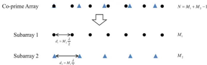
FIGURE 1. System model of a co-prime linear array.
Notations:in this paper, bold lowercase letters and bold capital letters symbolize vectors and matrices, respectively. Superscript (·)T, (·)∗ and (·)+ denote the transpose, com-plex conjugate and pseudo-inverse operator, respectively. | · | denotes the modulus operator and IM stands for the identity matrix with dimension M × M .
II. SYSTEM MODEL
Consider a co-prime linear array composed of two uni-form linear subarrays, having M1 and M2 sensors, with
inter-element spacing d1 = M2λ2 and d2 = M1λ2,
respec-tively, whereλ is the wavelength of incoming signals and M1
and M2are two co-prime integers. The first sensor is shared
by the two subarrays and set as the reference point. The total number of sensors is N = M1+ M2−1. FIGURE1shows
the situation where M1=7 and M2=5.
Suppose that there are K (K is supposed to be known and
K< min{M1, M2}) uncorrelated, far-field and narrowband
signals coming from directions {θ1, θ2, . . . , θK}, respectively, with −90◦< θ
k < 90◦and 1 ≤ k ≤ K . The signal received at the ithsubarray is xi(t) = K X k=1 ai(θk)sk(t) + ni(t) =Ais(t) + ni(t) (1) where Ai = [ ai(θ1) ai(θ2) · · · ai(θK) ] is the directional matrix of the ith subarray, with directional vector ai(θk) = [ 1 ejM˜iπ sin θk · · · ej(Mi−1)M˜iπ sin θk]T, i, ˜i ∈ {1, 2} and i 6= ˜i;
s(t) = [ s1(t) s2(t) · · · sK(t) ]T denotes the source signals vector with sk(t) the signal transmitted by the kth source and received at the reference sensor, and ni(t), which is assumed to be independent from the source signals, is the white Gaussian noise vector with zero-mean and covariance matrixσ2IMi, withσ
2the noise power.
Due to the property of sinusoid function, for the signal coming from θk and impinging on the ith subarray, there exists a unique angle denoted asθimap,k (−90◦< θimap,k < 90◦), satisfying
sinθimap,k = M˜isinθk+2ni,k (2) where ni,k is an integer with −
M˜i+1
2 < ni,k<
M˜i+1 2 .
Because of the property of the complex exponential func-tion, the directional vector associated to this signal can be re-written as amapi (θimap,k ) = [ 1 ejπ sin θimap,k· · ·ej(Mi−1)π sin θimap,k ]T. Therefore,θimap,k can be considered as the mapped angle on a
virtual half-wavelength spacing ULA of the true DOAθk on the ithsubarray. Consequently, the received signal model of the ithsubarray can be considered as K source signals coming from K mapped anglesθimap,k which impinge on a Mi-element virtual half-wavelength spacing ULA. Equation (1) can then be re-written as xi(t) = K X k=1 amapi (θimap,k )sk(t) + ni(t) =Amapi s(t) + ni(t) (3) where Amapi = [ amapi (θimap,1 ) aimap(θimap,2 ) · · · amapi (θimap,K )] is the mapped directional matrix of the ithsubarray, and the set of the K mapped angles associated to the K DOAs for the
ith subarray is defined as 2mapi = {θmap i,1 , θ
map i,2 , . . . , θ
map i,K }. Unlike the method in [11], which performs DOA estimation with the original signal model (1) and deals with the ambi-guities directly, considering the potential problems discussed in SectionIII, the mapped angleθimap,k in (2) and the virtual half-wavelength spacing ULA signal model (3) will serve as the basis for the proposed method.
III. PROBLEM FORMULATION
In this section, the three main problems associated to the DOA estimation with two co-prime subarrays, including ambiguity, pair matching errors and grating angles problem, will be described.
A. AMBIGUITY
Because of the large inter-element spacing, for the signal coming fromθk and impinging on the ithsubarray, only the mapped angleθimap,k can be obtained rather than the true DOA θk after DOA estimation. According to (2), each mapped angle θimap,k corresponds to M˜i candidate angles. The mth candidate angleθicand,k ,mcan be recovered by
θcand,m i,k =arcsin( 1 M˜i(sinθ map i,k −2n m i,k)) (4) which is directly deduced from (2), with nmi,kthe value of ni,k associated with the mthcandidate angleθicand,k ,m.
One of the candidate angles recovered by (4) is the true DOAθk, and the others are ambiguous angles. This problem is called ambiguity. According to the co-prime property of
M1and M2, the true DOAθkcan be uniquely determined by finding the common angle in the two sets of candidate angles recovered from the mapped anglesθ1map,k andθ2map,k , which are obtained from the two subarrays respectively [11], [12].
B. PAIR MATCHING ERROR
In the step of ambiguities elimination, the K common ele-ments (the true DOAs) among the candidate angles recovered from all the mapped angles in 2map1 and2map2 should be found. However, in the situation of multiple incoming signals, there may also exist common angles in the candidate angles recovered from the mapped angles of different sources in
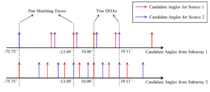
FIGURE 2. Pair matching errors.
different subarrays, resulting in more than K common angles, and consequently pair-matching errors occur. For example, consider the situation where M1 =7, M2=5, and two
sig-nals come fromθ1=10.00◦andθ2=39.11◦. The candidate
angles obtained from the two subarrays and associated to the two sources respectively are shown in FIGURE2. It can be seen that besides the two true DOAs, there exist two other common candidate angles, −13.09◦and −75.75◦, recovered from the mapped angles associated to different sources in different subarrays, resulting in pair-matching errors.
Therefore, the mapped angles estimated from the two sub-arrays associated to a common source should be pair matched, such that for each of the K pairs of matched angles, two sets of candidate angles can be recovered, and the associated true DOA can be obtained by finding the common element among them without pair matching errors [13], [14].
C. GRATING ANGLES PROBLEM
When some signals come from a set of distinct angles, which belong to a common candidate angles set, or in other words, which are grating angles to each other, their mapped angles will be the same. Consequently, their associated directional vectors will be identical and the directional matrix of this subarray will be rank deficient. It will result in difficulties for the subsequent steps like DOA estimation and ambiguities elimination for the methods proposed in [13], [14], which are based on the full rank property of the two directional matrices. To provide a better understanding, let’s consider the sit-uation where M1 = 7 and M2 = 5, and three
sig-nals come from θ1 = 10.00◦, θ2 = 27.35◦ and θ3 =
35.01◦, respectively. Their mapped angles for the 1stsubarray and the 2nd subarray are 2map1 = {θmap
1,1 , θ
map
1,2 , θ
map
1,3 } =
{60.25◦, 17.29◦, 60.25◦}and2map2 = {θmap
2,1 , θ
map
2,2 , θ
map
2,3 } =
{−51.67◦, −51.67◦, 0.92◦}respectively. It can be seen that θ1 and θ3 are grating angles to each other for the 1st
sub-array because they have the same mapped angle. For the same reason, θ1 and θ2 are grating angles to each other
for the 2nd subarray. Then the directional matrices of the two subarrays Ai (i ∈ {1, 2}) in (1) are rank deficient and the DOA estimation methods proposed in [13] and [14], which are based on the full rank assumption of A1 and
A2, cannot correctly work. For this antenna array
config-uration, the grating angles problem also occurs in many other situations. As an example with three incoming signals,
X. Yang et al.: Efficient DOA Estimation Method for Co-Prime Linear Arrays
FIGURE 3. Equivalent system model of a subarray.
when {θ1, θ2, θ3} = {20.00◦, 38.88◦, 47.90◦}, {θ1, θ2, θ3} =
{30.00◦, 51.79◦, 64.16◦} and many other configurations, the phenomenon occurs. It is a real problem which cannot be ignored [15].
IV. PROPOSED DOA ESTIMATION METHOD
Considering the grating angles problem or the rank deficiency of the directional matrices, in this section, an equivalent sys-tem model is introduced. Then an efficient DOA estimation method is proposed. Compared with the existing methods [11], [13]–[15], the proposed method can deal with any situ-ations with higher accuracy and lower complexity.
A. EQUIVALENT SYSTEM MODEL
When some signals come from a set of angles, which are grat-ing angles to each other for one subarray, the mapped angles of them are the same, or in other words, these signals seem to come from a ‘‘same’’ direction to the virtual half-wavelength spacing ULA. In this situation, the received signal model of the ith subarray can be regarded as Ki equivalent sig-nals seqvi,l (t) coming from Kidifferent equivalent anglesθieqv,l , (1 ≤ Ki ≤ K and 1 ≤ l ≤ Ki), impinging on a virtual half-wavelength spacing ULA, as shown in FIGURE3. Let’s define the set of the Kiequivalent angles of the ithsubarray as 2eqvi = {θeqv i,1 , θ eqv i,2 , . . . , θ eqv i,Ki}. Note that2 eqv i ⊆ 2 map i , and without grating angles problem, we have Ki = K and 2eqv
i =2 map
i , and the equivalent system model is identical to the system model introduced in Section II. In practice, the number of equivalent signals Ki can be estimated by Akaike Information Criterion (AIC) or Minimum Descrip-tion Length (MDL) methods [16]. When the grating angles problem occurs, some of the equivalent signals seqvi,l (t) should be a combination of some original signals sk(t), as shown in FIGURE3.
The signals observed at the ith subarray can then be re-written as
xi(t) = Ki
X
l=1
amapi (θieqv,l )seqvi,l (t) + ni(t)
=Aeqvi seqvi (t) + ni(t) (5)
where Aeqvi = [ amapi (θieqv,1 ) aimap(θieqv,2 ) · · · amapi (θieqv,K
i)]
is the equivalent directional matrix, and seqvi (t) = [ seqvi,1(t) seqvi,2(t) · · · seqvi,K
i(t) ]
T is the equivalent source signal vector of the ithsubarray.
B. DOA ESTIMATION
Based on the equivalent system model, after estimating the number of equivalent source signals Ki, the ESPRIT method can be performed and two sets of equivalent angles can be obtained from the two subarrays, denoted as ˆ2eqv1 = { ˆθeqv 1,1, ˆθ eqv 1,2, . . . , ˆθ eqv 1,K1} and ˆ2 eqv 2 = { ˆθ eqv 2,1, ˆθ eqv 2,2, . . . , ˆθ eqv 2,K2},
respectively. To achieve the pair matching of the equiva-lent angles, the equivaequiva-lent source signals vectors seqvi (t) of the two subarrays should be recovered. The pair match-ing of the equivalent angles is achieved by explormatch-ing the cross-correlations between their associated equivalent signals.
Based on the equivalent angles estimated previously, an estimated equivalent directional matrix can be constructed for each subarray as follows
ˆ
Aeqvi =[ amapi ( ˆθieqv,1) aimap( ˆθieqv,2 ) · · · amapi ( ˆθieqv,K
i) ] (6)
with the estimated mapped directional vector amapi ( ˆθieqv,l ) = [ 1 ejπ sin ˆθieqv,l · · ·
ej(Mi−1)π sin ˆθieqv,l ]T (7)
Then the equivalent source signals of the ithsubarray can be recovered by
ˆ
seqvi (t) = ( ˆAeqvi )+xi(t) (8) where ˆseqvi (t) = [ ˆseqvi,1(t) ˆseqvi,2(t) · · · ˆseqvi,K
i(t) ]
T denotes the obtained equivalent source signals vector.
In order to study the cross-correlations between the equiv-alent source signals of the two subarrays got by (8), K1× K2
cross-correlations can be estimated by
ˆ rp,q= 1 J J X t=1 ˆseqv1,p(t)(ˆseqv2,q(t))∗ (9)
where 1 ≤ p ≤ K1, 1 ≤ q ≤ K2 and J is the number of
snapshots.
Since an equivalent source signal may be a combination of some original source signals, if a common original signal is contained in two equivalent source signals ˆseqv1,p(t) and ˆseqv2,q(t), the modulus of the cross-correlation between them |ˆrp,q| would be a large value. Otherwise, it turns out to be a small value. On the other hand, thanks to the co-prime property between M1and M2, two distinct DOAs with same mapped
angle for one subarray have necessarily different mapped angles for the other subarray [15], [17]. Therefore, in the
K1× K2cross-correlations, there exist K cross-correlations
with large modulus corresponding to the K original sources. By finding the K cross-correlations with largest modulus, the K pairs of matched angles can be found. Similarly to (4),
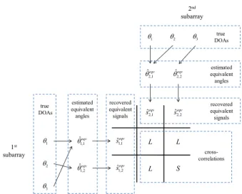
FIGURE 4. Processing flow chart for a normal situation.
for each pair of matched equivalent angles, two sets of candi-date angles can be recovered by
θcand,m i,k =arcsin( 1 M˜i(sin ˆθ eqv i,k −2n m i,k)) (10) and the true DOAθkcan be obtained by finding the common angle among them.
As a matter of illustration of this principle, the processing flow charts of the proposed method for a normal situation and a grating angles problem situation are depicted in FIGURE4
and FIGURE 5 respectively, where ‘‘L’’ stands for a large value and ‘‘S’’ stands for a small value. It is assumed that three signals impinge on the co-prime array from {θ1, θ2, θ3};
in the grating angles problem situation (FIGURE5),θ1and
θ3are grating angles for the 1stsubarray, andθ1andθ2are
grating angles for the 2nd subarray. It can be seen that the proposed method can overcome the rank deficiency caused by grating angles problem, and the estimation results can be pair matched automatically. Finally, two sets of candidate angles can be recovered from each pair of matched equivalent angles, and the common element among them can be found to obtain the true DOAs. The main steps of the proposed method can be summarized in TABLE1.
V. SIMULATION AND ANALYSIS
To assess the performance of the proposed method in every situation, firstly, the proposed method is compared with the method in [11] in a pair matching errors situation. Then, in a grating angles problem situation, it is compared with the methods in [13] and [14], which solve the pair matching errors. Finally, in order to assess the accuracy and complexity performance of the proposed method, it is compared with the method in [15], which also considers the pair matching errors and grating angles problem.
A. RELIABILITY COMPARISON
To show the superiority of the proposed method in pair-matching error situations, consider the situation
FIGURE 5. Processing flow chart for a grating angles problem situation.
TABLE 1.Main steps of the proposed method.
mentioned in SectionIII-B, where M1=7, M2=5, and two
signals come fromθ1=10.00◦andθ2=39.11◦respectively.
The reliability comparison of the proposed method and the method in [11] is shown in FIGURE 6, with 10 indepen-dent runs, in which the signal-to-noise ratio (SNR) is 0dB and the number of snapshots is 200. It can be seen that because the method in [11] only finds out the common elements in the candidate angles estimated from the two subarrays without pair matching, the estimation results may be ambiguous. In contrast, the proposed method can achieve the pair matching of the equivalent angles of the same source in different subarrays by exploring the cross-correlations between the equivalent signals, and the performance remains remarkable and stable.
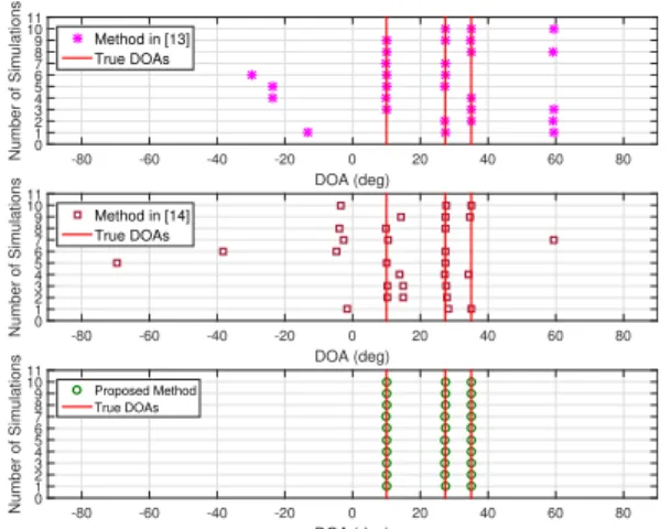
To emphasize the superiority of the proposed method in grating angles problem situations, consider again the situation
X. Yang et al.: Efficient DOA Estimation Method for Co-Prime Linear Arrays
FIGURE 6. Reliability comparison in the pair matching errors situation.
FIGURE 7. Reliability comparison in the grating angles problem situation.
mentioned in Section III-C, where M1 = 7, M2 = 5, and
three signals come from θ1 = 10.00◦, θ2 = 27.35◦ and
θ3 =35.01◦ respectively. The reliability comparison of the
proposed method with the methods in [13] and [14] is shown in FIGURE 7, with 10 independent runs, in which SNR is 0dB and the number of snapshots is 200. It is obvious that although the methods in [13] and [14] can overcome the pair matching errors with beamforming-based methods and the relationship between the directional matrices of the two sub-arrays, they ignore the fact that the directional matrices would be rank deficient due to the grating angles problem, and their performance cannot remain stable. In contrast, thanks to the equivalent system model, the equivalent directional matrices are full rank, and the correctly matched equivalent angle pairs can be found by exploring the cross-correlations between the equivalent signals. Thus it can work correctly in such situations.
B. ACCURACY COMPARISON
To assess the DOA estimation performance of the proposed method, the Root Mean Square Error (RMSE) is used as performance measurement, which is defined as
RMSE = v u u u t 1 KQ K X k=1 Q X q=1 ( ˆθq,k−θk) 2 (11)
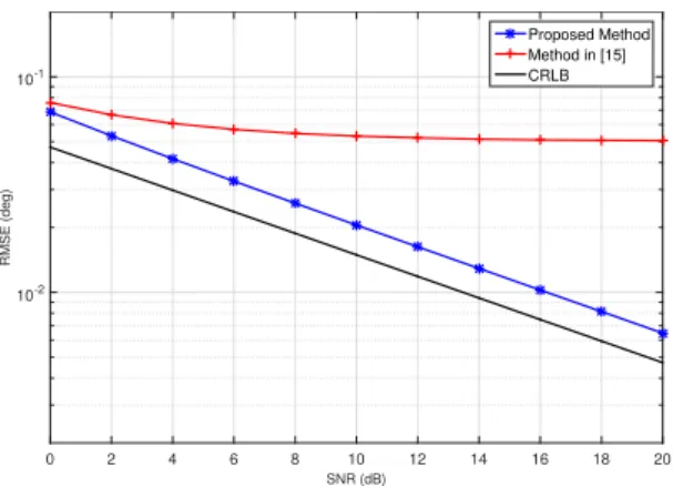
FIGURE 8. RMSE comparison versus SNR in the normal situation.
FIGURE 9. RMSE comparison versus snapshots number in the normal situation.
with K the number of incoming signals, Q the number of Monte Carlo trials, and ˆθq,k the estimate of the true DOA θk at the qth Monte Carlo trial. Q = 500 is used, and a co-prime linear array with M1=7 and M2=5 is considered.
The Cramér-Rao lower bound (CRLB) for this co-prime array geometry is also given as a benchmark [18].
The RMSE performance of the proposed method and the method in [15] is compared in a normal situation, where two signals are assumed to come from θ1 = 10.00◦
and θ2 = 40.00◦, and a grating angles problem
situ-ation, where three signals are assumed to impinge from θ1 = 10.00◦, θ2 = 27.35◦ and θ3 = 35.01◦,
ver-sus SNR (snapshots number is 200) and snapshots num-ber (SNR is 10dB). FIGURE8–FIGURE11 illustrate the obtained results. Because the peak-searching in the method in [15] is performed in the sine domain, the searching step is chosen as 0.001 to obtain a precise estimation. It can be seen that both methods can achieve a remarkable performance in grating angles problem situations, but since a ‘‘beamforming-like’’ method is utilized, the accuracy of the method in [15] is limited. On the contrary, based on the ESPRIT method, the proposed method can acquire a better estimation result, and its RMSE curves are closer to the CRLB.
C. COMPLEXITY COMPARISON
According to SectionIV-B, the proposed method requires the covariance matrices estimation, eigenvalue decomposition
FIGURE 10. RMSE comparison versus SNR in the grating angles problem situation.
FIGURE 11. RMSE comparison versus snapshots number in the grating angles problem situation.
FIGURE 12. Complexity comparison versus sensors number.
of the covariance matrices, equivalent signals recovery and cross-correlation computation. The resulting complexity is given as O((M12+M22)J +(M13+M23)+5K2(M1+M2)+6K3+
(M1+ M2)KJ + K2J). For the method in [15], it requires the
cross-covariance matrix estimation, singular value decom-position of the cross-covariance matrix and peak-searching, with the order of complexity O(M1M2J +4M1M22+ M23+
3M1K2+2K3+ M2M2×sch1K ), where J is the number of
snap-shots and sch is the searching step length. The complexity comparison versus the total number of sensors (M1+ M2−1)
is given in FIGURE12, with K = 2, J = 200. The search-ing step length is set as 0.0001 to achieve a similar RMSE performance between the two algorithms. It can be observed
that without peak-searching, the proposed method has lower computational complexity, thus the DOA estimation can be accomplished more efficiently.
For the other methods in [11], [13], [14], their practicability is limited by the pair matching errors or grating angles prob-lem. Therefore, their performance in terms of accuracy and complexity is less significant in the case of real applications.
VI. CONCLUSION
In this paper, the existing problems associated to the DOA estimation with co-prime linear arrays, including ambigu-ity, pair matching errors and grating angles problem, are discussed. Based on the equivalent system, a reliable and efficient DOA estimation method is proposed. True DOAs are mapped into their corresponding equivalent angles, and after their estimation, the corresponding equivalent signals can be recovered from the received signals. Then the pair matching of the equivalent angles can be achieved by exploring the cross-correlations between the equivalent signals. Simulation results show that the proposed method is able to achieve a better estimation performance than other existing methods, in terms of accuracy and complexity.
REFERENCES
[1] H. Kim and M. Viberg, ‘‘Two decades of array signal processing research,’’
IEEE Signal Process. Mag., vol. 13, no. 4, pp. 67–94, Jul. 1996. [2] M. L. Bencheikh, Y. Wang, and H. He, ‘‘Polynomial root finding technique
for joint DOA DOD estimation in bistatic MIMO radar,’’ Signal Process., vol. 90, no. 9, pp. 2723–2730, Mar. 2010.
[3] C. Zhang, H. Huang, and B. Liao, ‘‘Direction finding in MIMO radar with unknown mutual coupling,’’ IEEE Access, vol. 5, pp. 4439–4447, 2017. [4] R. O. Schmidt, ‘‘Multiple emitter location and signal parameter
estima-tion,’’ IEEE Trans. Antennas Propag., vol. AP-34, no. 3, pp. 276–280, Mar. 1986.
[5] R. Roy and T. Kailath, ‘‘Esprit-estimation of signal parameters via rotational invariance techniques,’’ IEEE Trans. Acoust., Speech, Signal
Process., vol. 37, no. 7, pp. 984–995, Jul. 1989.
[6] P. P. Vaidyanathan and P. Pal, ‘‘Sparse sensing with co-prime samplers and arrays,’’ IEEE Trans. Signal Process., vol. 59, no. 2, pp. 573–586, Feb. 2011.
[7] S. Qin, Y. D. Zhang, and M. G. Amin, ‘‘Generalized coprime array config-urations for direction-of-arrival estimation,’’ IEEE Trans. Signal Process., vol. 63, no. 6, pp. 1377–1390, Mar. 2015.
[8] C.-L. Liu and P. P. Vaidyanathan, ‘‘Remarks on the spatial smoothing step in coarray MUSIC,’’ IEEE Signal Process. Lett., vol. 22, no. 9, pp. 1438–1442, Sep. 2015.
[9] Q. Xie, X. Pan, and S. Xiao, ‘‘Enhance degrees of freedom for coprime array using optspace algorithm,’’ IEEE Access, vol. 7, pp. 32672–32680, 2019.
[10] X. Li, Y. Cao, B. Yao, and F. Liu, ‘‘Robust generalized chinese-remainder-theorem-based DOA estimation for a coprime array,’’ IEEE Access, vol. 6, pp. 60361–60368, 2018.
[11] C. Zhou, Z. Shi, Y. Gu, and X. Shen, ‘‘DECOM: DOA estimation with combined MUSIC for coprime array,’’ in Proc. IEEE Int. Conf. Wireless
Commun. Signal Process., Oct. 2013, pp. 1–5.
[12] F. G. Sun, P. Lan, and B. Gao, ‘‘Partial spectral search-based DOA esti-mation method for co-prime linear arrays,’’ Electron. Lett., vol. 51, no. 24, pp. 2053–2055, Nov. 2015.
[13] F. Sun, B. Gao, L. Chen, and P. Lan, ‘‘A low-complexity ESPRIT-based DOA estimation method for co-prime linear arrays,’’ Sensors, vol. 16, no. 9, p. 1367, 2016.
[14] D. Zhang, Y. S. Zhang, G. M. Zheng, C. Q. Feng, and J. Tang, ‘‘Improved DOA estimation algorithm for co-prime linear arrays using root-MUSIC algorithm,’’ Electron. Lett., vol. 53, no. 18, pp. 1277–1279, Sep. 2017.
X. Yang et al.: Efficient DOA Estimation Method for Co-Prime Linear Arrays
[15] X. Yang, X. Wu, S. Li, and T. K. Sarkar, ‘‘A fast and robust DOA esti-mation method based on JSVD for co-prime array,’’ IEEE Access, vol. 6, pp. 41697–41705, 2018.
[16] M. Wax and T. Kailath, ‘‘Detection of signals by information theoretic criteria,’’ IEEE Trans. Acoust., Speech, Signal Process., vol. ASSP-33, no. 2, pp. 387–392, Apr. 1985.
[17] W. Zheng, X. Zhang, P. Gong, and H. Zhai, ‘‘DOA estimation for coprime linear arrays: An ambiguity-free method involving full DOFs,’’ IEEE
Commun. Lett., vol. 22, no. 3, pp. 562–565, Mar. 2018.
[18] P. Stoica and A. Nehorai, ‘‘Performance study of conditional and uncondi-tional direction-of-arrival estimation,’’ IEEE Trans. Acoust., Speech Signal
Process., vol. 38, no. 10, pp. 1783–1795, Oct. 1990.
XIAO YANG received the B.E. degree in elec-tronic information engineering from Hebei United University, Tangshan, China, in 2014, and the M.S. degree in electronic system from the École Polytechnique de l’Université de Nantes, France, in 2016.
He is currently pursuing the Ph.D. degree with the École Polytechnique de l’Université de Nantes. His research interest includes array signal processing.
YIDE WANG received the B.S. degree in elec-trical engineering from the Beijing University of Posts and Telecommunications, Beijing, China, in 1985, and the M.S. and the Ph.D. degrees in sig-nal processing and telecommunications from the University of Rennes, France, in 1986 and 1989, respectively.
He is currently a Professor with the École Poly-technique de l’Université de Nantes, France. His research interests include array signal processing, spectral analysis, and mobile wireless communication systems.
PASCAL CHARGÉ was a Researcher Fellow with the Dynamical System Team, LATTIS Labora-tory, University of Toulouse, from 2003 to 2010. Since 2010, he has been with the Communica-tion Systems (SYSCOM) Research Team, IETR (UMR CNRS) Laboratory. Since 2017, he has been responsible of the SYSCOM Team, IETR. He is currently a Professor with the École Poly-technique de l’Université de Nantes, France. His research interests include array signal processing for wireless communications, techniques and technologies for the spectrum sensing, localization techniques, statistical signal processing, and nonlinear dynamical systems.
YUEHUA DING received the M.S. degree in elec-trical engineering from the South China Univer-sity of Technology (SCUT), Guangzhou, China, in 2008, and the Ph.D. degree in signal processing and telecommunications from the École Polytech-nique de l’Université de Nantes, France, in 2011.
He is currently an Associate Professor with the School of Electronic and Information Engineering, SCUT. His research interests include array signal processing in communications, cognitive radios, MIMO communication systems, and multi-antenna technologies.