O
pen
A
rchive
T
oulouse
A
rchive
O
uverte (
OATAO
)
OATAO is an open access repository that collects the work of Toulouse researchers and makes it freely available over the web where possible.
This is an author-deposited version published in: http://oatao.univ-toulouse.fr/
Eprints ID:3941
To link to this article:
doi:10.4028/www.scientific.net/MSF.636-637.517 URL: http://dx.doi.org/10.4028/www.scientific.net/MSF.636-637.517
To cite this version: Niang, A. and Huez, Julitte and Lacaze, Jacques and Viguier, Bernard ( 2010) Characterizing Precipitation Defects in Nickel
based 718 Alloy. Materials Science Forum, vol. 636-637 . pp. 517-522.
ISSN 0255-5476
Any correspondence concerning this service should be sent to the repository administrator: [email protected]
Characterizing Precipitation Defects in Nickel based 718 Alloy
A. Niang
a, J. Huez
b, J. Lacaze
cand B. Viguier
dUniversité de Toulouse, CIRIMAT, ENSIACET, 118 Route de Narbonne, 31077 Toulouse, France.
a
[email protected], [email protected], [email protected],
d
Keywords: Nickel base superalloys, Inconel 718, Ni3Nb, Gamma double prime, HRTEM, Stacking
faults.
Abstract. In the present study we examine the crystallographic structure of the J, J’’ and G phases present in nickel base 718 alloy. The chemical ordering of Nb atoms and possible planar faults that may be observed in J’’ precipitates are detailed. High resolution transmission electron microscopy (HRTEM) observations of various faults are reported. The decomposition of a matrix dislocation to form a locked V shaped configuration is shown. The observation along [110] type direction allows to identify the type of defect, which is observed as a pure geometric stacking fault.
Introduction
Polycrystalline nickel base 718 alloy is widely used in aerospace and energy industry, specially for turbine disks and other applications that require high strength materials for temperature up to 650°C. This alloy exhibits good mechanical properties in the intermediate temperature range and good ability for forming processes. The strength of this alloy comes from coherent precipitates, which are for a small part γ’-Ni3(Al,Ti) but mostly γ"-Ni3Nb [1-4]. Both of these precipitates are ordered forms of the γ Ni rich matrix (face centred cubic–A1). The ordered γ’ phase presents the cubic L12 structure and the γ" is body centred tetragonal corresponding to the D022 structure. The γ" phase is a metastable form of Ni3Nb which tends to stabilize to the orthorhombic δ phase with the structure D0a. The evolution of the precipitation state which can occur during thermal and mechanical ageing, is responsible for the evolution of mechanical properties of the alloy [5,6]. The softening of the alloy, through the transformation of fine J’’ precipitates to the stable phase G is particularly important [7]. It has been shown [2,7,8] that the growth of G at the expense of γ" precipitates is often associated with the formation of stacking faults (SF’s) within these latter. The aim of the paper is focused on such SF’s which may exist in γ" precipitates. We first present the crystallographic structure of γ, γ" and δ phases, showing how the transformations between those phases may occur. Then we present an experimental characterization of SF’s observed in γ" precipitates and we discuss possible mechanism for their formation, in relation with the generation of stable G precipitates.
Crystallographic structure of phases
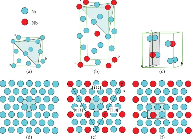
The crystallographic structure of the three phases involved in the present study, namely J, J” and G, are shown in Fig. 1. The unit cells are shown in Fig. 1(a, b and c). They respectively consist in a) a fcc cell with a = 0.3616 nm ; b) a bct cell with a = 0.3624 nm and c = 0.7046 nm (note that these parameters lead to c/a ≈ 1.94 so that the tetragonal cell can be viewed as two cubes superposed along the c axis) and c) an orthorhombic cell with a = 0.5141 nm, b = 0.4231 nm and c = 0.4534 nm. The J” and G precipitates are commonly observed with epitaxial relations with the fcc structure of the J matrix. Such relations, which are expressed as:
'' ) 112 //( ) 111 ( J J - [110] //[110] '' J J and (111)J //
010 G - [110]J //[100]G,
actually meaning that there exists a correspondence between the compact planes and directions of the three structures. Those compact planes are shown as grey surfaces within the unit cells in Fig 1 (a, b and c) and the atomic arrangement of the atoms in the planes are depicted in Fig. 1(d, e and f) in which the surfaces greyed in the unit cells have been reported. These drawing show that the compact planes of each structure: (111)γ, (112)γ" and (010)δ, correspond to a close packing of atoms, with an additional chemical order in the case of J” and G phases. It is important to notice that these compact planes are identical for both ordered phases, with the same rectangular arrangement of Nb atoms within the plane. In this view it appears that the difference between J and J” phases is based on a chemical ordering of Nb atoms on the same cubic geometry. For the sake of simplicity the directions and plane indices will be given in the cubic crystallographic basis (with the relation [001]J // [001]J”) so that the compact plane denoted (111) corresponds to (112)J” and (010)G. In this ordered plane, see Fig. 1 (d), two types of compact directions exist: along [110] half atomic rows are Ni/Nb alternated and the other half are pure Ni; whereas along [011] and [101] all atomic rows are equivalently mixed 3Ni/1Nb atoms.
a b c a b c a b c (a) (b) (c) (d) (e) (f)
Fig. 1. Unit cell (a, b and c) and atomic arrangement in the corresponding compact planes (d, e and f) for the phases γ (A1), γ" (D022) and δ(D0a) respectively.
The difference between the structures of the γ"-Ni3Nb and the δ-Ni3Nb phases lies in the difference in the stacking mode of these close-packed planes. In the D022 structure, this stacking sequence is similar to the cubic stacking fashion based on a sequence of three planes (ABCABC..). However, due to the chemical order within the compact plane in the case of D022 structure the stacking sequence extends over six planes depending on the location of the Nb atoms. This is better viewed in Fig. 2 (a) which represents the projection of the structure along the [110] direction. The resulting sequence can be written as A1B1C1A2B2C2A1… where the letters (ABC) indicate the
Ni Nb
geometric position of the atoms and the numbers (12) their chemical nature. This stacking insures that each Nb atom is surrounded by twelve Ni atoms so that there never exists in the structure two Nb atoms as nearest neighbours. The stacking of compact planes in the D0a structure is shown in Fig. 2(b), it corresponds to a sequence of two planes ABABAB…(similar to hexagonal compact packed structure, however as the compact plane shows a two fold symmetry not six fold due to the rectangular arrangement of Nb atoms, the structure possesses orthorhombic symmetry). Note that such stacking also insures that each Nb atom is surrounded by twelve Ni nearest neighbours and that there never exists any Nb atoms as nearest neighbours, just like in J” phase.
(a) (b)
Fig. 2. Illustration of the stacking of the compact planes in γ" (a) and δ (b) phases projected along ]
10 1
[ as indicated in Fig.1. The large disks indicate the atoms in the plane, they correspond to projected rows of alternated Nb and Ni atoms. The small disks represent the atoms beyond the projection plane, they correspond to pure Ni rows. Note that for the J” phase (a) we have written directions in the cubic J basis (with the relation [001]J // [001]J”).
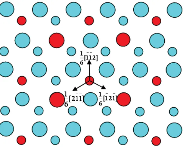
We have seen that J” and G phases only differ in the way the ordered close-packed planes are stacked. Just like in disordered fcc structure, a localised alteration of the stacking sequence corresponds to a SF which is associated with the shearing of the crystal by one Shockley partial dislocation [9]. Partial dislocation Burgers vectors are shown in Fig. 3, in which two overlapping ordered close-packed planes of the D022 structure are represented. As one can see in Fig. 3, the three <112> directions are not equivalent. Indeed, the displacement provoked by 16[112] (equivalent to
J cc ] 1 1 1 [ 6
1 ) partial dislocation changes the type of plane without changing the neighbouring of the selected Nb atom. In the D022 stacking sequence, such Burgers vector would transform a B1 plane to C2, leading to the stacking A2B2C2A1C2A1B1C2 which includes two AC sequences of planes
corresponding locally to the D0a structure. Alternatively, the displacement by the Burgers vectors ] 1 1 2 [ 6 1 and [121] 6 1 (respectively equivalent to " 6 1 [421]
J and 16[241]J") implies that the Nb atom which was sitting on a three Ni atoms triangle is now in contact with a Nb atom as nearest neighbour. In other words the resulting plane does not correspond to any of the A1 to C2 plane of the D022 staking sequence nor to the A or B planes of the D0a sequence. Such displacement, which modifies the neighbouring of the Nb atoms, corresponds to a complex SF and is likely to be energetically quite unfavourable. The above crystallographic considerations show that for each compact plane in the J” phase there exists only one Burgers vector available to create a low energy stacking fault, corresponding to the formation of G like structure over four crystallographic planes. In this case the J” → G transformation can be viewed as a purely geometrical modification. Despite those remarks were already mentioned for quite a long time [2,8,10], no experimental
characterization of the type of SF was reported previously. The consequences of this particularity on the formation of stacking faults in J” precipitates were neither discussed. These two points will be addressed below.
Fig. 3. Stacking of two successive ordered compact (111) planes showing three possible partial dislocation Burgers vectors. Large disks represent atoms on the ground plane, and the smaller disk atom of the plane which lies on top of the earlier (crystallographic indices are given in the cubic J basis).
Experimental details
Direct experimental observations of SF’s within γ" precipitates have been conducted on specimens extracted from an alloy 718 billet provided by Aubert & Duval. The observations reported here were realised on the as-received and heat treated 1000°C/1s samples taken from a study of the J” and G precipitation kinetics [11]. Thin foils were classically prepared from bulk samples by cutting and grinding 3 mm diameter disks to the final thickness of about 100 µm. Electron transparency was obtained by electropolishing the foil in a Struers twin-jet Tenupol-5, using usual electrolyte and operating at about -10°C, under 22 Volts. Conventional and high resolution transmission electron microscopy (HRTEM) observations were realised at the TEMSCAN (Service Commun de Microscopie Electronique de l’Université Paul Sabatier, Toulouse) with a JEOL2100F equipped with a field emission gun and working at 200 kV.
(a) (b) Fig. 4. TEM observations of SF’s (white arrows) within γ" precipitates imaged using conventional
Results and discussions
In the present study the observations made on grains containing quite large J” precipitates are reported, since SFs are commonly observed in such large precipitates. It is worth noting that the sample observed did not undergo any plastic deformation after high temperature treatment, so that the SF’s observed were formed during the growth of J” precipitates. In the different grains, that were objects of study, the presence of the three possible J” variants in the form of circular plates (about 100 nm in diameter and 20 nm thick) was noticed. Numerous SF’s are observed in γ" precipitates as indicated by the white arrows in Fig. 4 (a). Similar observations of SF’s in large J” precipitates have been often reported in the literature [10,12,13]. However such observations do not allow characterizing precisely the exact morphology and nature of the SF’s, the interpretation is almost limited to the statement that there exists some SF’s. A more precise characterization of those defects can be achieved by HRTEM observations. Such an image is shown in Fig. 4 (b), in which one can see two SF’s lying on two secant {111} planes and that are connected to form a V shape. This image is taken along a [101] type direction, along which the ordered structure of J” is not detectable since all projected rows include alternatively Nb and Ni atoms, see Fig. 1(e).
(a)
(b)
(c)
Fig. 5. (a) HRTEM image of a SF within a γ" precipitate viewed along [110], to be compared with the schematic projection of atoms in the case of a SF created by 16[112] (b) or [121]
6
1 (c).
Low magnification observations show that the whole defect entirely lies within a J” precipitate. A Burgers circuit drawn around the whole defect evidences a closure vector within the
111 plane which corresponds to the projection of a Burgers vector of the type 12 011 . The identification of the Burgers vector of each partial dislocation and the structure of planar faults would necessitate the use of computer simulated images [14] and the comparison between simulated and experimental images as this was done in different intermetallic compounds [15]. The present observation also
shows that a dislocation with a Burgers vector of the type 12 011 can dissociate into several partial
dislocations and form complex configuration. It must be noted that the observed configuration is not mobile but would instead act as a lock. The mechanism by which during the plastic deformation of the alloy, the matrix dislocations shear the precipitates and create SF’s [7,8] is clearly different from the dissociation mode observed in the present study. Such crossing mechanism still needs to be elucidated, particularly it is not clear how the same matrix dislocation would be able to cross J” precipitates of different variants.
In some circumstances, the direct interpretation of HRTEM images allows to determine the type of SF. This is illustrated in Fig. 5, corresponding to observations performed along [110] zone axis. In this case, (002) planes are projected and correspond to a succession of alternate Ni/Nb rows and pure Ni rows. This structure results in a image with modulated contrast over two (002) planes as can be seen in Fig. 5 (a). Thanks to this special contrast, the shift in (002) planes across the SF can be directly quantified and compared with the schematics of Figs 5 (b) and (c). It is indeed clear that the insert in Fig. 5 (a) compares very well with Fig. 5 (b) and not with Fig. 5 (c). The SF is thus associated with a displacement by the vector 16[112] (equivalent to
J cc ] 1 1 1 [ 6
1 ), i.e. the vector that creates a purely geometric SF without chemical fault. Although it has been anticipated for quite a long time that this kind of fault is more likely to occur than a fault that would change the nearest neighbours of atoms [2], the present observation is to our knowledge its first experimental evidence.
Conclusions
1. The crystallographic structure of the J, J” and G phases appearing in alloy 718 are examined in details, showing that the J → J’’ transformation consists of a chemical ordering of the Nb atoms without changing the geometry, whilst the J’’ → G transformation is purely a geometrical modification of the compact planes stacking sequence.
2. Dissociation of ½<011> type dislocation in the form of V shaped lock has been evidenced. 3. HRTEM observations along [110] zone axis allow to identify the type of fault which is observed,
we reported observation of purely geometric SF.
References
[1] D. F. Paulonis, J. M. Oblak and D. S. Duvall: Trans. ASM. Vol. 62 (1969), p. 611 [2] I. Kirman and D. Warrington: Metallurgical Transactions Vol. 1 (1970), p. 2667 [3] R. Cozar and A. Pineau: Metall. Trans. Vol. 4 (1973), p. 47
[4] J. M. Oblak, D. F. Paulonis and D. S. Duvall: Metall. Trans. Vol. 5 (1974), p. 143 [5] C. Slama, C. Servant and G. Cizeron: J. Mater. Res. Vol. 12 (1997), p. 2298
[6] S. Coste, E. Andrieu and J. Huez: Materials Science and Eng. Vol. A 396 (2005), p. 92
[7] J. Dong, X. Xie, Z. Xu and S. Zhang, in : Superalloys 718, 625, 706 and Various Derivatives, edited by E.A. Loria, The Minerals, Metals and Materials Society (1994) p. 649
[8] M. Sundararaman, P. Mukhopadhyay and S. Banerjee: Metall. Trans. Vol. A 19 (1988), p. 453 [9] J.P. Hirth and J. Lothe : Theory of Dislocations (Wiley, NewYork 1982)
[10] K. Kusabiraki: Metallurgical Science and Technology Vol. 13 (1997), p. 369 [11] A. Niang, B. Viguier and J. Lacaze, to be published (2009)
[12] M. Sundararaman, P. Mukhopadhyay and S. Banerjee: Metall. Trans. Vol. A 23 (1992), p. 2015
[13] K. Kusabiraki, T. Tsutsumi and S. Saji: Metal. and Mat. Trans. Vol. A 30 (1999), p. 1923 [14] P.A. Stadelmann: Ultramicroscopy, Vol. 21 (1987), p. 131
![Fig. 2. Illustration of the stacking of the compact planes in γ" (a) and δ (b) phases projected along ]](https://thumb-eu.123doks.com/thumbv2/123doknet/3688240.109390/4.918.129.800.278.553/fig-illustration-stacking-compact-planes-γ-phases-projected.webp)