This is an author-deposited version published in:
http://oatao.univ-toulouse.fr/
Eprints ID: 4131
To cite this document:
FERRANDIZ Thomas, FRANCES Fabrice, FRABOUL
Christian. An enhanced worst-case end-to-end evaluation method for SpaceWire
networks. In: 22nd Euromicro Conference on Real-Time Systems - ECRTS10, 06-09 Juil
2010, Bruxelles, Belgique.
Any correspondence concerning this service should be sent to the repository
administrator:
[email protected]
An enhanced worst-case end-to-end evaluation
method for SpaceWire networks
Thomas Ferrandiz
Univ. of Toulouse, ISAE Email: [email protected]Fabrice Frances
Univ. of Toulouse, ISAE Email: [email protected]Christian Fraboul
Univ. of Toulouse, IRIT/ENSEEIHT-INPT Email: [email protected]
Abstract—The SpaceWire network is scheduled to be used as the sole on-board network for future ESA satellites. However, at the moment, network designers do not have tools to ensure that critical temporal deadlines are met when using best-effort wormhole networks like SpaceWire. In a previous paper, we have presented a first method to compute an upper-bound on the worst-case end-to-end delay of flows traversing such networks. However, its scope was limited by restrictive assumptions on the traffic patterns. Thus, in this paper, we propose a new network model that removes those limitations and allows worst-case delay analysis on SpaceWire networks with any traffic pattern.
I. INTRODUCTION
End-to-end (ETE) transmission delays vary a lot in a wormhole network and are very hard to predict. This raises a problem when trying to use a wormhole network to transmit traffics with hard temporal constraints. Sev-eral mechanisms have been studied to make wormhole networks more suitable for real-time communications like virtual channels [1] and preemptive priorities. How-ever, those mechanisms increase memory consumption and cannot always be employed.
For instance, the SpaceWire standard [2],[3] that the European Space Agency plans to use for on-board real-time communications in its future satellites is a best-effort wormhole network and does not include such mechanisms.
Since delays cannot be determined analytically, an-other good metric is to use an upper-bound on the worst-case ETE transmission delay. We proposed a first method to compute such a bound in [4]. However, our method required some restrictions on the traffic model. First, it made the assumptions that data packets were long enough not to be entirely stored inside the switches buffer which are only 64-byte large. Second, it could not model a situation where two packets of the same flow were present in the network at the same time and interfering with each other. As a consequence, it was too specific to cover every pertinent cases.
Network-On-Chips (NoCs) are another area where a similar need emerged. Those networks also have to transmit real-time traffic while keeping memory and power consumption low. Several papers deal with this problem (for instance [5] and [6]) but only offer partial solution at the moment. In [7], the authors present a model called RTB-HB (Real-Time Bound for High-Bandwidth traffic) that allows them to compute worst-case latency bounds for best-effort wormhole NoCs. This model does not require assumptions on the traffic model but assumes a synchronous network and is optimized for small packet sizes.
Based on our previous work and the RTB-HB model, we present a new network model that does not re-quire assumptions on the traffic pattern anymore. It lets terminals send data at any time and works for any packet sizes. The first step in the model is to break down wormhole switches in elementary components as shown in Section II. We then show in Section III how to determine delay bounds for those components and compose them to derive worst-case ETE delays. Finally, we conclude in Section IV and present future topics for research.
II. MODEL OF ASPACEWIRE SWITCH
SpaceWire [2],[3] was designed by the European Space Agency and the University of Dundee as a high-speed on-board network for satellites. It uses point-to-point links and wormhole switches to interconnect terminals. Wormhole routing allows switches to use a very small amount of memory but, as shown in [4], it is subject to blockings that create large variations in delays. In this Section, we present an analysis of the different type of blockings and a model that simplifies the analysis of their impact.
Figure 1 shows a 8x8 SpaceWire switch with 8 inde-pendent ports. Since the input and output of each port work independently of each other, we will separate them in the model. Each input port is connected to a FIFO input buffer. Typically, SpaceWire switches use 64-byte
input buffers. A switch matrix then connects the input buffers to the output ports according to the destination of the packet.
Figure 1. A 8x8 SpaceWire switch
A. Blocking types analysis
In such a switch, two kinds of delay can slow down a packet. The first one is a delay when the packet tries to access an output port. If a packet is already using it, the switch matrix cannot connect the input port to the output port. Thus the packet has to wait until the current transmission is finished. Since the access to the output port is managed with a Round-Robin mechanism, other packets may also pass before the considered packet gets access to the output port.
The second one occurs when a packet p gets blocked behind a packet q in the FIFO buffer. Depending on the size of q, its header can be in the same buffer, or in the next switch or even farther in the network. Even if q does not use the same output port as p, p will not be able to access its output port as long as a part of q is in the buffer.
These two kinds of blockings combined together mean that the ETE delay of the packets of a given flow may vary enormously across different transmissions. How-ever, by breaking down a switch in elementary switches and analyzing them individually, we will be able to get a simpler model and to determine a bound on the ETE delay.
B. The switch model
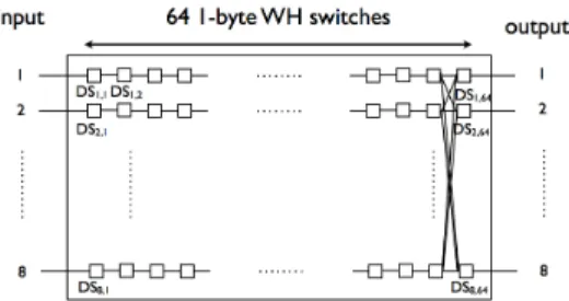
The model is based on the idea that, as far as delays are concerned, a 64-byte FIFO buffer is identical to 64 successive wormhole switches with a one byte buffer, connected by links of infinite capacity. The model is shown on Figure 2.
DSk,l denotes the lth elementary switch (with l ∈ {1, . . . 64}) of the input buffer of port k, k ∈ {1, . . . 8}. For each k, DSk,1 to DSk,62 have one input port and one output port and a switching delay of 0 s.
Figure 2. Equivalent of a SpaceWire switch using elementary switches
DSk,63 and DSk,64 model the switching matrix of the real switch. DSk,63 has one input port and 8 output ports. Its switching delay is equal to the switching delay of the real switch. It uses a routing table equivalent to that of the real switch. Each DSk,63is connected to each of the DSk,64 to model the connections in the switch matrix. The DSk,64switches have 8 input ports and one output port. Each input port has a one-byte input buffer. This elementary switch model the access conflicts to the output port of the real switch and arbitrates between the different input ports with a Round-Robin mechanism.
To ensure that the model matches exactly the behavior of a SpaceWire switch, we need to make one more assumption. Since each DSk,64 has 8 one-byte input buffers, it looks like there are more memory available than in the real switch. However, this is not the case if we make sure that at any time, only one DSk0,64, k0 ∈ {1, . . . 8} can contain a character coming from a given DSk,63. So the condition for a packet to move forward from DSk,63to a DSk0,64 is not only that the DSk0,64 it wants to access is free, it is that all the DSk0,64are free, for all k0 ∈ {1, . . . 8}. With this condition, it is easy to see that the character stream coming from a given input port can never use more than 64 bytes.
We can now use this switch model to compute an upper-bound on the worst-case ETE delay of each flow.
III. COMPUTING AN UPPER-BOUND ON THE WORST-CASE END-TO-END DELAY
The computation takes place in two phases. Firstly, it takes a description of a SpaceWire network as input and creates an ”elementary network” composed only of terminals and 1-byte elementary switches connected by unidirectional links. Secondly, this ”elementary network” is used to compute the worst-case delay for each flow by adding up the delays caused by each of the elementary switch crossed by the flow.
A. Assumptions
We consider that a SpaceWire network is composed of terminals (that can each both emit and receive data) and
of switches that interconnect them through SpaceWire links. We assume that a terminal has only one network interface.
We do not make any assumptions on the emission patterns of the terminals. This allows us to consider terminals without input traffic regulations as is the case for most terminal at the moment. Each terminal can try to send a data packet at any time. We also assume that at the beginning of the computation, all the input buffers of all the switches are already full and that all the flows are trying to emit at maximum speed. This allows us to cover all the possible worst-case situations and find an upper-bound on the worst-case delay.
A communication between a source and a destination is modeled as a flow fi, i ∈ {1, . . . N }. Each flow fihas a fixed packet size, noted Li. Each flow goes through a set of links that form a path in the network between two terminals.
We also make the following assumptions: • the routing is static;
• all the links have the same capacity C;
• the destination of a packet is able to read it as fast as the network can transmit it
• each terminal needs a constant delay dinj to inject a packet in the network.
• each terminal needs a constant delay dej to eject a packet from the network.
B. Generating the ”elementary network”
The first step is to replace every SpaceWire switch by the equivalent set of elementary switches as explained in II-B. Now each flow will follow a path of elementary switches connected by unidirectional links. We will note hi the number of those elementary switches and SWij, j ∈ {1, . . . , hi} the jth switch in this path. Note that hi only counts the elementary switches representing the SpaceWire switches.
We then need to model the terminals. Each terminal may play two roles: source and destination. Since we use unidirectional links in the elementary network, those roles must be modeled separately.
A source terminal injects packets from one or more flows in the network at maximum speed. All the flows are competing for access to the output link. This is arbitrated through a Round-Robin mechanism. Therefore, we chose to model a source terminal as a set of elementary sources (one for each outgoing flow) connected to an elementary switch arbitrating between the flows. The elementary switch will be denoted SW0
i.
Similarly, a destination terminal will receive packets from the network from one or more flow and eject them as they arrive. If we had modeled a destination
terminal as a single elementary block, when adding up the delays in each crossed elementary switches, we would only get the time needed for the header of the packet to reach its destination. To obtain the transmission delay of the whole packet, we chose to add Li − 1 elementary switches to the path of each flow fi after SWhi
i . Thus we model a destination terminal as an elementary switch receiving all the flows ending in this terminal and dispatching them to an additional path of Li − 2 elementary switches. Each path ends with an elementary destination. Those elementary switches are connected by infinite capacity links.
In the end, a packet from flow fi has to cross hi+Lielementary switches (from SWi0to SW
hi+Li−1
i )
to reach its elementary destination. We now have a complete network of elementary blocks which we can use to compute ETE delays.
C. Upper-bound computation
This method is inspired by the RTB-HB method from [7] and we will use mostly similar notations. We note uji the delay needed for a packet pi of flow fi to go from the input buffer of switch SWij to the input buffer of SWij+1. Given these notations, an Upper-Bound on the ETE transmission delay of flow fi is given by
U Bi= dinj+ dej+
X
j∈{0,...,hi+Li−1}
uji. (1)
Similarly, we can compute a Minimum Interval between two packets of the same flow with
M Ii= dinj+
X
j∈{0,...,Li−1}
uji. (2) M Iirepresents the minimum delay needed to completely move a packet out of the source buffer. This metric can be used to derive a maximum available bandwidth for each flow and determine if a network is able to transmit all the required traffic.
Let us now compute uji. The causes of delay in a switch are twofold. On one hand, since we assume that the network is completely filled with packets, the downstream elementary switch SWij+1contains the last character of another packet pi0. So pi0 has to move forward one hop before pi can go on. Since pi0 is Li0 -byte long, its header is in SWj+Li0
i0 . When the header of pi0 moves one hop forward, all the packet will follow. As a consequence, the delay before pi0 frees SWij+1 is uj+Li0
i0 .
Let zc(i, j) be the number of flows in conflict with fi in SW
j
i. For elementary switches with only one output link, zc(i, j) is obviously equal to the number of flows entering the switch (excluding fi). For elementary
switches with several output links, as explained in Sec-tion II-B, we must make sure that they are all free before pi can move. As a consequence, we can also consider that all the flows entering SWij are competing with fi for access to the output port. In addition, pi0 may belong to fi itself.
In the end, for every elementary switch, the delay caused by pi0 in the worst case is maxi0∈{1,...,z c(i,j)}(u j+Li i , u j+Li0 i0 ).
On the other hand, delays can be caused by packets coming from other input links and using the same output link as fi. With wormhole routing, if another packet is already using the output port, pi has to wait until this packet has been completely transferred before it can move forward. In addition, packets from other flows may be already waiting for this port to be released and will be transferred before pi.
However, as we showed in [4], because of the Round-Robin mechanism, for a given input port, only one packet may pass before pi. Thus, to get the worst-case delay, for each input port, we will compute the delay that each flow could cause and take the maximum of those delays. We can then sum those delays for all the input links to get the maximum delay endured by pi.
Furthermore, a packet pi0 entering SWij+1 from a different input link than pi must move forward Li0 hops before it releases the output port. Therefore it causes a delay equal toPLi0
k=1u j+k i0 .
Let us denote Iij ={input links of SWij minus the input link of fi} and Flj ={flows entering SWij through l}. The worst-case delay caused by all the flows coming from other input ports than pi is given byP l∈Iij(maxi0∈Fj l {PLi0 k=1u j+k i0 }) In the end, uji is given by
max i0∈{1,...,z c(i,j)} (uj+Li i , u j+Li0 i0 ) + X l∈Iji ( max i0∈Fj l { Li0 X k=1 uj+ki0 }) (3) (3) can now be used to compute (1) and (2) recursively for each flow fi. The computation ends when the packet reaches its destination. Since SpaceWire characters are 10-bit long, we can write this so: ∀j > hi, u
j i =
10 C. IV. CONCLUSION
We have presented a new network model designed to determine an upper-bound on the worst-case end-to-end transmission delay of data packets traversing a SpaceWire network. This model was inspired by works on similar problems in wormhole switching Networks-On-Chip. In our model, wormhole switches and termi-nals are broken down in elementary switches that can
be easily analyzed to determine delay bounds. Those bounds can then be composed to derive a bound on the end-to-end delay of each flow.
Contrary to our previous work, this model does not need strong assumptions on the traffic patterns. It works for switches without dedicated real-time mechanisms and does not require traffic regulation at the terminals.
A first implementation shows preliminary results that are coherent with our previous work in configurations where our first method was applicable. We also intend to do a more complete comparison between our model and the RTB-HB method [7] which inspired it in the future.
We plan to develop our model in several directions. A first direction will be to generalize it to support other wormhole switching networks than SpaceWire. The first step in this direction will be to support links with different capacities throughout the network. This aspect is crucial to make the method more general. The second direction will be to model more functionalities specific to the SpaceWire standard like switch-level priorities and Group Adaptative Routing.
ACKNOWLEDGMENT
This work was supported by a PhD grant from the CNES and Thales Alenia Space.
REFERENCES
[1] W. Dally, “Virtual-channel flow control,” Parallel and Distributed Systems, IEEE Transactions on, vol. 3, no. 2, pp. 194 – 205, Mar 1992.
[2] S. M. Parkes and P. Armbruster, “Spacewire: A spacecraft onboard network for real-time communications,” IEEE-NPSS Real Time Conference, no. 14, pp. 1–5, Feb 2005.
[3] ECSS, “Spacewire – links, nodes, routers and networks,” pp. 1– 129, Aug 2008.
[4] T. Ferrandiz, F. Frances, and C. Fraboul, “A method of com-putation for worst-case delay analysis on spacewire networks,” Industrial Embedded Systems, 2009. SIES ’09. IEEE International Symposium on, pp. 19 – 27, 2009.
[5] Z. Shi and A. Burns, “Real-time communication analysis with a priority share policy in on-chip networks,” Real-Time Systems, 2009. ECRTS ’09. 21st Euromicro Conference on, pp. 3 – 12, Jul 2009.
[6] Y. Qian, Z. Lu, and W. Dou, “Analysis of worst-case delay bounds for best-effort communication in wormhole networks on chip,” Proceedings of the 2009 3rd ACM/IEEE International Symposium on Networks-on-Chip-Volume 00, pp. 44–53, 2009.
[7] D. Rahmati, S. Murali, L. Benini, F. Angiolini, G. D. Micheli, and H. Sarbazi-Azad, “A method for calculating hard qos guar-antees for networks-on-chip,” Computer-Aided Design - Digest of Technical Papers, 2009. ICCAD 2009. IEEE/ACM International Conference on DOI -, pp. 579–586, 2009.