READ THESE TERMS AND CONDITIONS CAREFULLY BEFORE USING THIS WEBSITE. https://nrc-publications.canada.ca/eng/copyright
Vous avez des questions? Nous pouvons vous aider. Pour communiquer directement avec un auteur, consultez la première page de la revue dans laquelle son article a été publié afin de trouver ses coordonnées. Si vous n’arrivez pas à les repérer, communiquez avec nous à PublicationsArchive-ArchivesPublications@nrc-cnrc.gc.ca.
Questions? Contact the NRC Publications Archive team at
PublicationsArchive-ArchivesPublications@nrc-cnrc.gc.ca. If you wish to email the authors directly, please see the first page of the publication for their contact information.
NRC Publications Archive
Archives des publications du CNRC
This publication could be one of several versions: author’s original, accepted manuscript or the publisher’s version. / La version de cette publication peut être l’une des suivantes : la version prépublication de l’auteur, la version acceptée du manuscrit ou la version de l’éditeur.
Access and use of this website and the material on it are subject to the Terms and Conditions set forth at
Comparison of NBC (1985) seismic provisions with Japanese seismic
regulations (1981)
Ishiyama, Y.
https://publications-cnrc.canada.ca/fra/droits
L’accès à ce site Web et l’utilisation de son contenu sont assujettis aux conditions présentées dans le site LISEZ CES CONDITIONS ATTENTIVEMENT AVANT D’UTILISER CE SITE WEB.
NRC Publications Record / Notice d'Archives des publications de CNRC:
https://nrc-publications.canada.ca/eng/view/object/?id=03135acd-cd96-4001-ba52-4b5d3cfc43b9 https://publications-cnrc.canada.ca/fra/voir/objet/?id=03135acd-cd96-4001-ba52-4b5d3cfc43b9- - - -
THI
Y
ational Research
Conseil national
N2ld
Zouncil Canada
de recherches Canada
Division des
BLDG
3uilding Research
recherches en bdtiment
Comparison of NBC (1985) Seismic
Provisions with Japanese Seismic
Regulations (198 1)
by Yuji lshiyama
ANALYZED
DBR Paper No.
1297NRCC 24684
Price $3.00
COMPARISON OF NBC (1985) SEISMIC PROVISIONS WITH JAPANESE SEISMIC REGULATIONS (1981)
ANALYZED
by Yuj i Ishiyama
Noise and V i b r a t i o n Sect i o n D i v i s i o n of Building Research DBR Paper No. 1297 July 1985 ISSN 0381-4319 NRCC 24684 P r i c e $ 3 . 0 0
COMPARISON OF NBC (1985) SEISMIC PROVISIONS WITH
JAPANESE SEISMIC REGULATIONS (1981)
Yuj
i Ishiyama*
ABSTRACT
The National Building Code of Canada 1985 has modified the seismic
provisions relative to the 1980 Edition. In Japan, the new aseismic design
method has been in force since 1981. This paper compares both codes
considering the main factors involved in the seismic load calculation and
points out some problems yet to be solved. Finally, research subjects are
suggested.
1.
INTRODUCTION
The National Building Code of Canada 1985~
has substantially
modified the seismic provisions, compared to those in the 1980
code.
2,In Japan, new seismic regulations for buildings4 have been
in force for all buildings since 1981. The regulations were made
after a five-year national research project to develop new aseismic
design methods and a three-year review.
Though the codes in Canada and Japan have introduced up-to-date
knowledge of seismology, earthquake engineering, design and
construction practices, etc., there seems to be room for improvement,
not only through future developments of research and practice but also
in the state of present knowledge, which is not adequately considered
in the codes. This paper intends to compare the Canadian and Japanese
seismic codes, to indicate the problems which should be solved, and to
suggest research which should be carried out in order to improve the
seismic codes.
The National Building Code of Canada provides technical
requirements for ensuring public safety in buildings and is adopted
and then used in municipal bylaws or provincial codes.
The Building Standard Law in Japan has been in force for all
buildings since 1950 to safeguard the lives, health and property of
the people and to increase the public welfare. The umbrella law was
promulgated through the approval of the National Diet. The detailed
regulations pertaining to aseismic design were made by Enforcement
Order of the cabinet, notifications from the Ministry of Construction,
etc. The new aseismic design method comprises the revised enforcement
order, notifications and related regulations in force since 1981.
*Visiting Fellow at Noise and Vibration Section, Division of Building
Research, National Research Council Canada. On leave from International
Institute of Seismology and Earthquake Engineering, Building Research
Institute, Ministry of Construction, Government of Japan.
Throughout this paper, "NBC" refers to the seismic provisions of
the National of Building Code of Canada (1985) and "BSL" refers to the
seismic regulations of the Building Standard Law of Japan and related
Enforcement Order, notifications and regulations in force since 1981.
2.
DESIGN PROCEDURE
The design procedure in NBC is to calculate the stresses on
structural members caused by the load due to earthquakes and to design
the members for stresses of various load combinations of factored
loads using limit states design. Though working stress design is
included in the NBC, it is gradually being less used (Table 1).
The design procedure in BSL is to calculate the stresses on
structural members caused by the load due to moderate earthquake
motions and to design the members for stresses of load combinations of
permanent load and seismic load using working stress design (Table 1).
Furthermore, for buildings higher than 31 m it is required to
calculate the ultimate lateral shear strength of each storey and to
confirm it to be not less than the specified ultimate lateral shear
for severe earthquake motions. This will be explained later in more
detail. For buildings less than 31 m in height, special requirements
are specified, i.e. a minimum wall/column ratio, prevention of brittle
failure of structural members, etc. Flow charts of the various design
requirements for concrete and steel structures are given in
Appendices A and B, respectively.
TABLE 1 Load C o m b i n a t i o n s f o r S e i s m i c Design NBC BSL L i m i t S t a t e s D e s i g n Working S t r e s s D e s i g n
-
Working S t r e s s D e s i g n C o n c r e t e O t h e r Than C o n c r e t e 0.75(D+L+Q) 1.4D+0.75(1.4L+1.8Q) 1.25D+O.7(1.5L+1.54) D+L+Q* D: Dead Load L: L i v e Load Q: S e i s m i c Load *The s t r e s s e s by t h i s l o a d c o m b i n a t i o n s h o u l d b e l e s s t h a n t h e a l l o w a b l e stresses f o r s h o r t - t e r m l o a d which a r e 1.5 t o 2.0 t i m e s l a r g e r t h a n t h e a l l o w a b l e stresses f o r l o n g - t e r m l o a d .3. SEISMIC
LOAD
3.1 Method t o Define Seismic Load
The NBC s t i p u l a t e s t h e base s h e a r V by t h e f o l l o w i n g formula:
where: v = zonal v e l o c i t y r a t i o ( s e e Section 3.3); S = s e i s m i c response f a c t o r ( s e e S e c t i o n 3.4); K = numerical c o e f f i c i e n t f o r s t r u c t u r a l behaviour ( s e e S e c t i o n 3.6); I = importance f a c t o r ( s e e S e c t i o n 3.7); F = f o u n d a t i o n f a c t o r ( s e e Section 3.8); and W = weight of t h e b u i l d i n g ( s e e S e c t i o n 3.9).
The base s h e a r i s then d i s t r i b u t e d a l o n g t h e h e i g h t of t h e b u i l d i n g . The BSL s t i p u l a t e s t h e l a t e r a l s e i s m i c s h e a r c o e f f i c i e n t Ci of t h e i - t h s t o r e y by: where: Z = zoning c o e f f i c i e n t ( s e e S e c t i o n 3.3); R t = design s p e c t r a l c o e f f i c i e n t ( s e e Section 3.4); Ai = l a t e r a l s h e a r d i s t r i b u t i o n f a c t o r ( s e e S e c t i o n 3.10); and C o = s t a n d a r d s h e a r c o e f f i c i e n t ( s e e Section 3.3). The l a t e r a l s e i s m i c s h e a r Vi of t h e i - t h s t o r y i s c a l c u l a t e d by:
where:
W i
= weight of t h e b u i l d i n g above t h e i - t h s t o r e y .BSL g i v e s t h e s h e a r which i s produced a t a c e r t a i n l e v e l of t h e b u i l d i n g and then t h e f o r c e a t t h a t l e v e l is c a l c u l a t e d a s t h e
d i f f e r e n c e between t h e s h e a r s a t and above t h i s l e v e l . NBC g i v e s t h e base s h e a r , then t h e l a t e r a l f o r c e a t each l e v e l
i s
determined i n p r o p o r t i o n t o t h e weight and s t o r e y h e i g h t from t h e ground l e v e l . The s h e a r d i s t r i b u t i o n along t h e h e i g h t of t h e b u i l d i n g r e s u l t s from a summation of l a t e r a l f o r c e s . It should be noted t h a t t h e s e twod i f f e r e n t methods of c a l c u l a t i n g t h e s e i s m i c load along t h e h e i g h t of t h e b u i l d i n g g i v e s i m i l a r s h e a r d i s t r i b u t i o n s ( s e e Section 3.10). 3.2 Base Shear C o e f f i c i e n t
The base s h e a r c o e f f i c i e n t CB f o r NBC i s :
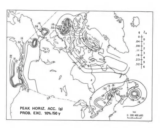
Figure l a . Acceleration-related seismic zone Za (NBC) ( a f t e r Heidebrecht, e t a1. 5,
Figure lb. Velocity-related seismic zone Zv (NBC) ( a f t e r Heidebrecht
,
e t a1. 5 ,The f a c t o r s i n Equations
( 4 )
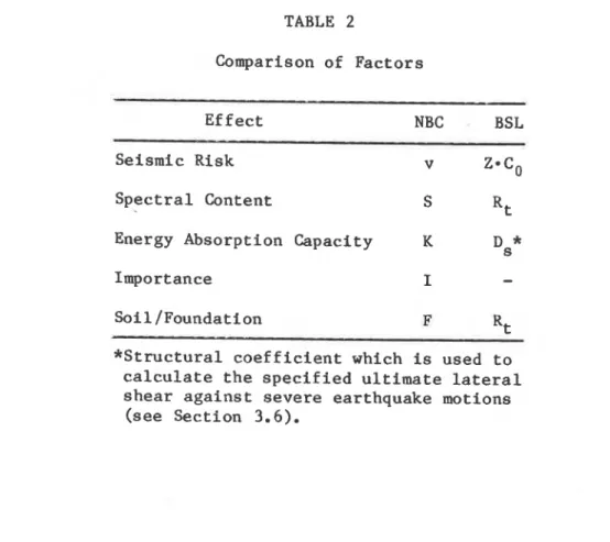
and ( 5 ) i n c l u d e t h e e f f e c t s of: ( a ) s e i s m i c r i s k ; ( b ) s p e c t r a l c o n t e n t ; ( c ) energy a b s o r p t i o n c a p a c i t y ; ( d ) importance; and ( e ) s o i l / f o u n d a t i o n a s shown i nTable 2.
3.3 Seismic Zoning
The s e i s m i c zoning maps i n NBC 1985 (Figs. l a and l b ) 5 d i f f e r from t h e maps i n NBC 1980 i n : ( a ) d a t a a n a l y s e s ; ( b ) ground motion a t t e n u a t i o n r e l a t i o n s ; ( c ) ground motion parameters (not only
a c c e l e r a t i o n but a l s o v e l o c i t y ) ; and ( d ) t h e p r o b a b i l i t y of
exceedance. I n s h o r t , t h e s e i s m i c r i s k i s expressed by two maps: one t h a t g i v e s zones derived from t h e peak ground a c c e l e r a t i o n ( t h e
parameter t h a t i s governed mainly by t h e e f f e c t of n e a r f i e l d e a r t h q u a k e s ) , and t h e o t h e r g i v e s zones d e r i v e d from peak ground v e l o c i t y (mainly governed by f a r earthquakes). The p r o b a b i l i t y of
exceedance t h a t corresponds t o t h e s e peak ground motion parameters
i s
10% i n 50 years.
Figure l b g i v e s t h e v e l o c i t y - r e l a t e d s e i s m i c zone Z v and t h e corresponding zonal v e l o c i t y r a t i o v which governs mainly t h e l o n g e r period s t r u c t u r e s o r h i g h e r b u i l d i n g s . Figure l a g i v e s t h e
a c c e l e r a t i o n - r e l a t e d s e i s m i c zone Za which governs mainly t h e s h o r t e r p e r i o d o r lower buildings. The e f f e c t s of Za and Z a r e combined i n t o t h e s e i s m i c response f a c t o r S d e s c r i b e d i n Section 3 . 4 ( s e e a l s o Fig. 3). TABLE 2 Comparison of F a c t o r s E f f e c t NBC BSL Seismic Risk v Z * C 0 S p e c t r a l Content S R t
Energy Absorption Capacity K Ds*
Importance I
-
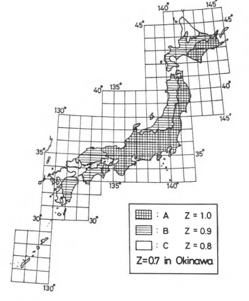
S o i l /Foundation F Rt * S t r u c t u r a l c o e f f i c i e n t which i s used t o c a l c u l a t e t h e s p e c i f i e d u l t i m a t e l a t e r a l s h e a r a g a i n s t s e v e r e earthquake motions ( s e e Section 3.6).The s e i s m i c zoning map i n BSL (Fig. 2) only i n d i c a t e s r e l a t i v e s e i s m i c i t y , d i v i d i n g Japan i n t o f o u r zones. The s e i s m i c zoning
c o e f f i c i e n t Z i s 1.0, 0.9, 0.8, and 0.7 from high s e i s m i c i t y zones t o low s e i s m i c i t y zones. It i s n o t e x p l a i n e d whether t h e s e v a l u e s a r e r e l a t e d t o a c c e l e r a t i o n o r t o v e l o c i t y . But c o n s i d e r i n g t h a t t h e s e i s m i c d e s i g n c o e f f i c i e n t h a s t h e u n i t of g r a v i t a t i o n a l a c c e l e r a t i o n , t h e s e i s m i c zoning c o e f f i c i e n t should be r e l a t e d t o a c c e l e r a t i o n . The p r o b a b i l i t y of exceedance i s a l s o n o t i n d i c a t e d . But comparing t h i s map t o t h e s e i s m i c contour l i n e s drawn by Japanese r e s e a r c h e r s , 9
t h e map seems t o be r e l a t e d n o t o n l y t o t h e s t a t i s t i c a l s e i s m i c i t y b u t a l s o t o t h e engineering experience t h a t has been employed i n Japan.
The s t a n d a r d s h e a r c o e f f i c i e n t C o r e f l e c t s t h e a b s o l u t e
s e i s m i c i t y i n Japan, and i s 0.2 f o r moderate earthquake motions and 1.0 f o r s e v e r e earthquake motions. This i s i n t e r p r e t e d a s follows. Moderate earthquake motions would occur s e v e r a l t i m e s during t h e u s e of t h e b u i l d i n g s , and t h e maximum a c c e l e r a t i o n a t t h e ground s u r f a c e
becomes 0.08 t o 0.1 g. The response of low-rise b u i l d i n g s may reach 0.2 g c o n s i d e r i n g a dynamic a m p l i f i c a t i o n of 2.0 t o 2.5. Severe earthquake motions would occur perhaps once d u r i n g t h e u s e of t h e b u i l d i n g s , t h e maximum a c c e l e r a t i o n a t t h e ground s u r f a c e may r e a c h 0.33 t o 0.4 g, and t h e e l a s t i c response of low-rise b u i l d i n g s may become 1 g c o n s i d e r i n g a dynamic a m p l i f i c a t i o n of 2.5 t o 3. The
1
g f o r c e i s t o o l a r g e f o r t h e economic design of u s u a l b u i l d i n g s and t h e r e f o r e i t can be reduced t o 0.25 t o 0.55, t a k i n g i n t o account t h e energy-absorbing c a p a c i t y , i.e., t h e d u c t i l i t y and t h e damping of s t r u c t u r e s ( s e e Ds i n Section 3.6).I n c i d e n t a l l y , t h e previous Japanese code c o n t a i n e d o n l y t h e s e i s m i c c o e f f i c i e n t k = 0.2, which corresponds t o t h e standard shear c o e f f i c i e n t f o r moderate earthquake motions i n t h e p r e s e n t code. It
d i d not c o n t a i n any p r o v i s i o n s f o r s e v e r e earthquake motions and consequently i t d i d n o t r e q u i r e t h e c a l c u l a t i o n of t h e u l t i m a t e l a t e r a l s h e a r s t r e n g t h .
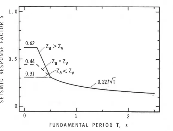
3.4 S p e c t r a l Content
The e f f e c t of t h e fundamental p e r i o d T of t h e b u i l d i n g i s
included i n t h e s e i s m i c response f a c t o r S (Fig. 3)
i n
NBC. The f a c t o r i s c o n s t a n t f o r s h o r t e r p e r i o d s o r lower b u i l d i n g s (T ( 0.25 s ) and d e c r e a s e s i n v e r s e l y i n p r o p o r t i o n t o t h e square r o o t of t h efundamental p e r i o d f o r l o n g e r p e r i o d s o r h i g h e r b u i l d i n g s
(T
) 0.5 s). The curves f o r t h e s e two regions a r e connected by s t r a i g h t l i n e s f o r 0.25 s<
T 6 0.5 s.F U N D A M E N T A L P E R I O D T,
s
Figure 3. Seismic response f a c t o r S (NBC)I n BSL, t h e design s p e c t r a l c o e f f i c i e n t Rt (Fig.
4)
i s
comparable t o t h e s e i s m i c response f a c t o r S i n NBC. The c o e f f i c i e n ti s
c o n s t a n t (R = 1) f o r T<
Tc, where Tc i s t h e c r i t i c a l p e r i o d whose value i s0.h, 0.6 o r 0.8 s , depending on t h e s o i l p r o f i l e . d e c r e a s e s h y p e r b o l i c a l l y according t o Rt = 1.6 Tc/T f o r T
>
2$c, whichcorresponds t o a c o n s t a n t v e l o c i t y response f o r l o n g e r periods. For Tc
<
T<
2T
t h e curves a r e smoothly connected by parabolas according t o = 1-
6.2 (TITc-
The smooth curve avoids t h e d r a s t i c change of design base s h e a r which occurs i n s p e c i f i e d design s p e c t r a where s h a r p c o r n e r s a r e p r e s e n t . This appears a p p r o p r i a t e s i n c e i n most c a s e s t h e fundamental p e r i o d i s only e s t i m a t e d by e m p i r i c a l formulae.Estimation of Fundamental Period
The fundamental p e r i o d T ( s ) i n NBC i s :
where: h = h e i g h t (m) above t h e base;
and Ds = dimension (m) of t h e l a t e r a l f o r c e r e s i s t i n g system i n t h e d i r e c t i o n of t h e a p p l i e d f o r c e s ; 1 I I I I I
-
-
-
-
-
M E D I U M S O l L
-
-
-
H A R D S O l L
-
-
-
-
-
-
-
-
I-
-
-
-
I I I I I IF U N D A M E N T A L P E R I O D T , s
Figure 4. Design s p e c t r a l c o e f f i c i e n tR t
(BSL)e x c e p t t h a t f o r moment r e s i s t i n g frames,
where: N = t o t a l number of s t o r i e s above e x t e r i o r grade.
T can be o b t a i n e d by o t h e r e s t a b l i s h e d methods b u t i t cannot b e more t h a n 1.2 t i m e s t h e v a l u e g i v e n by e i t h e r of t h e above formulae, [Equations ( 6 a ) and ( 6 b ) l . T i n BSL i s g i v e n by: where: or = t h e r a t i o of t h e h e i g h t of s t e e l c o n s t r u c t i o n ( b u i l t on t o p of c o n c r e t e c o n s t r u c t i o n ) t o t h e t o t a l h e i g h t of t h e b u i l d i n g . Thus, f o r a b u i l d i n g e n t i r e l y of c o n c r e t e , f o r one e n t i r e l y of s t e e l ,
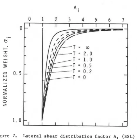
T can be c a l c u l a t e d by o t h e r e s t a b l i s h e d methods t h a n t h e above formulae, [Equations ( 7 ) , ( 7 a ) and ( 7 b ) l b u t t h e base s h e a r must n o t be less t h a n 0.75 of t h e b a s e s h e a r o b t a i n e d w i t h t h i s formula. However, t h e d i s t r i b u t i o n of t h e f o r c e s a l o n g t h e h e i g h t of t h e b u i l d i n g h a s t o be modified by t h e c a l c u l a t e d T a s p e r Fig. 7, which r e s u l t s i n l a r g e r f o r c e s being a p p l i e d t o t h e upper s t o r i e s f o r l o n g e r p e r i o d b u i l d i n g s .
F i g u r e 5 shows t h e comparison of fundamental p e r i o d s c a l c u l a t e d by t h e aforementioned formulae.
All
formulae i n d i c a t e t h e f a c t t h a t t h e h i g h e r t h e b u i l d i n g , t h e l o n g e r t h e fundamental p e r i o d . However, t h e l a r g e d i v e r g e n c e i n F i g u r e 5 may a l s o i n d i c a t e t h a t p r e c i s e e s t i m a t i o n of t h e fundamental p e r i o d i s i m p o s s i b l e by u s i n g a s i m p l e formula w i t h only a few parameters i n i t . From t h e viewpoint of p r a c t i c a l d e s i g n , t h e formula which g i v e s s m a l l e r v a l u e s w i l l be p r e f e r a b l e f o r a c h i e v i n g a more c o n s e r v a t i v e d e s i g n s i n c e i t r e s u l t s i n l a r g e r d e s i g n b a s e s h e a r . It s h o u l d be n o t e d t h a t i nBSL
t h e l o n g e r p e r i o d means n o t only a r e d u c t i o n i n t h e d e s i g n base s h e a r b u t a l s o a n i n c r e a s e of t h e f o r c e s a p p l i e d t o upper s t o r i e s . Thisc o n t r o l s d e s i g n e r s ' t e m p t a t i o n t o s e e k a l o n g e r p e r i o d f o r r e a s o n s of economy.
3.6 Energy-Absorbing Capacity
The numerical c o e f f i c i e n t K i n NBC reduces t h e s e i s m i c l o a d depending on t h e m a t e r i a l and t y p e of c o n s t r u c t i o n , damping, d u c t i l i t y , and/or energy-absorptive c a p a c i t y a s given i n Table 3.
I n BSL, t h e b u i l d i n g s should be i n t h e e l a s t i c range when s u b j e c t e d t o moderate earthquake motions. Therefore, t h e
energy-absorbing c a p a c i t y i s n o t t a k e n i n t o account i n t h e c a s e of t h e s t a n d a r d s h e a r c o e f f i c i e n t Co = 0.2.
I n t h e c a s e of s e v e r e earthquake motions, t h e b u i l d i n g cannot remain i n t h e e l a s t i c range and w i l l s u s t a i n t h e i n e l a s t i c response when s u b j e c t e d t o ground motion. Therefore, BSL r e q u i r e s d e s i g n a g a i n s t s e v e r e earthquake motions, by confirming t h a t t h e u l t i m a t e l a t e r a l s h e a r s t r e n g t h of each s t o r e y i s n o t less t h a n t h e s p e c i f i e d u l t i m a t e l a t e r a l s h e a r
xn
which i s given by:Qun Ds *es Qud
where: Ds = t h e s t r u c t u r a l c o e f f i c i e n t ; Fes = t h e shape f a c t o r = Fe Fs;
and Qud = t h e l a t e r a l s e i s m i c s h e a r f o r s e v e r e earthquake mot ions.
NBC
(STOREY
HEIGHT
3
m)7
,
,*I
-
4
-
-
3
-
-
2
-
-
=BSL (CONCRETE)
0
5
0
100
150
B U I L D I N G H E I G H T ,
rn
The s t r u c t u r a l c o e f f i c i e n t Ds ( s e e Tables 4a and 4b) can be
i n t e r p r e t e d a s t h e r e d u c t i o n f a c t o r of t h e e l a s t i c response f o r c e t h a t reaches 1 g d u r i n g s e v e r e earthquake motions, and t a k e s i n t o account
t h e energy-absorbing c a p a c i t y of t h e building. The shape f a c t o r Fes
i s t h e product of t h e shape f a c t o r due t o e c c e n t r i c i t y Fe ( s e e Section 4.1) and t h e shape f a c t o r due t o v a r i a t i o n of s t i f f n e s s Fs ( s e e Section 4.2).
It should be noted t h a t t h e r a t i o of t h e most d u c t i l e s t r u c t u r e
(K
= 0.7) t o t h e u s u a l s t r u c t u r e (K = 1.3) i n NBC i s approximately 0.5and t h e r a t i o of Ds = 0.25 t o Ds = 0.55 i n BSL i s almost t h e same.
The c l a s s i f i c a t i o n of s t r u c t u r e s becomes f r e q u e n t l y c o n t r o v e r s i a l
when Table 3 o r Tables 4a and 4b a r e used. Therefore, t h e p r e c i s e
d e s c r i p t i o n of s t r u c t u r e s i s very important. Appendices
C
and D a r etaken from t h e BSL manual8 t h a t provides guidance i n t h e a p p l i c a t i o n of Tables 4a and 4b t o r e i n f o r c e d c o n c r e t e b u i l d i n g s and s t e e l
b u i l d i n g s , r e s p e c t i v e l y .
TABLE 3
C o e f f i c i e n t K (NBC)
(With a b b r e v i a t e d d e s c r i p t i o n from Table 4.1.9.A of NBC 1985)
- - -
-S t r u c t u r a l Type of Buildings K
-
- - - - - -
1 D u c t i l e moment r e s i s t i n g space frame. 0.7
2
D u c t i l e moment r e s i s t i n g space frame with d u c t i l e f l e x u r a l w a l l s(frame must c a r r y a t l e a s t 25% of t o t a l s h e a r ) . 0.7 3 D u c t i l e moment r e s i s t i n g s p a c e frame w i t h s h e a r w a l l s o r s t e e l b r a c e s ( w a l l s o r b r a c e s t o c a r r y t o t a l s h e a r and frame t o c a r r y a t l e a s t 25% of t o t a l s h e a r ) . 0.8 4 Buildings w i t h d u c t i l e f l e x u r a l w a l l s o r w i t h d u c t i l e framing systems o t h e r than 1, 2, 3 o r 5. 1.0
5
D u c t i l e moment r e s i s t i n g space frame with w a l l s having masonryi n f i l l i n g ( w a l l w i t h i n f i l l i n g t o c a r r y t o t a l s h e a r , frame a t
l e a s t 25% of t o t a l shear). 1.3
-- --
6 Reinforced c o n c r e t e , s t r u c t u r a l s t e e l o r r e i n f o r c e d masonry s h e a r
w a l l s . 1.3
7* Unreinforced masonry and o t h e r than t h e above. 2.0
8 Elevated cross-braced tanks. 3.0
TABLE 4a
Structural Coefficient Ds for Buildings of Steel Construction (BSL)
Type of Frame
(1)
( 2 )(3)
Ductile
Frame Other Than
Frame Wi
th
Behaviour of Members
Moment Frame
(1) and (3)
Compression Braces
A.
Members of
excellent ductility
0.25
B.
Members of good
ductility
0.3
C. Members of fair
ductility
0.35
D. Members of poor
ductility
0.4
TABLE 4b
Structural Coefficient Ds for Buildings of Reinforced Concrete or
Steel-Encased-by-Reinforced-Concrete Construction (BSL)*
Type of Frame
(1
(2)
(3)
Ductile
Frame Other Than
Frame With
Behaviour of Members
Moment Frame
(1) and (3)
Shear Walls or Braces
A.
Members of
excellent ductility
0.3
0.35
0.4
B. Members of good
ductility
0.35
0.4
C. Members of fair
ductility
0.4
D. Members of poor
ductility
0.45
0.5
0.55
*Values are decreased by 0.05 for steel-encased-by-reinforced-concrete
construction.
3.7
Importance Factor
The importance factor I in NBC is
1 . 3for all postdisaster
buildings and schools and
1.0for all other buildings.
BSL does not include an importance factor for buildings because
BSL stipulates the minimum standard applicable for all buildings.
Before introducing the importance factor into the code, the
concept of importance of the building should be clarified. The
limitation of storey drift* or other requirements might be more
appropriate than the increase of design load by the importance factor.
The requirements for the building performance should be specified,
depending on the function that is required for the building during and
after earthquakes.
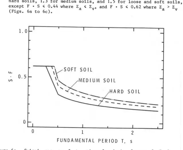
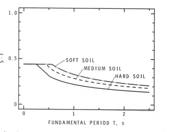
3.8
Effect of Soil Profile and Foundation
The foundation factor F for NBC is
1.0for very dense, stiff and
hard soils,
1 . 3for medium soils, and
1.5 for loose and soft soils,
except
F
S
G 0.44where Za
<
Z,,
and
F
.
S
<
0.62 where Za
>Zv
(Figs. 6a to 6c).
0
0
1
2
F U N D A M E N T A L P E R I O D T, s
Figure 6a. Seismic response factor times foundation factor,
S
OF,
for
Z
,
'
Z
,
(NBC)
r
r 1 I I I-
-
-
-
-
-
-
-
-
-
-
E D l U M S O I L
-
-
-
-
-
---.-
-
- - - -
-
-
-
-
-
I I I II
I . --*The difference of the horizontal deflections at the top and bottom of the
storey under consideration
F U N D A M E N T A L P E R I O D T ,
s
1 . 0
LI
-
0 . 5 -
Figure 6b. Seismic response f a c t o r times foundation f a c t o r , S F , f o r Za = Zv (NBC) - I I I I I I
-
-
-
-
-
-
-
-
-
/
S O F T S O I L
v1S O F T S O I L
-
H A R D S O l L
-
-
-
0
-
a I I I 3 I-
0
1
2
-.-.
M E D I U M S O l L ,
H A R D S O l L
F U N D A M E N T A L P E R I O D T ,
s
Figure 6c. Seismic response f a c t o r times f o u n d a t i ~ n f a c t o r ,
S
F,
f o r Za ( Z v (NBC)BSL does n o t e x p l i c i t l y s t i p u l a t e s o i l o r f o u n d a t i o n f a c t o r s , b u t t h e d e s i g n r e s p o n s e spectrum (Fig. 4) i n d i c a t e s t h e f a c t o r c a n b e c a l i b r a t e d a s
1.0
f o r h a r d s o i l s ,1.5
f o r medium s o i l s and2.0
f o r s o £ t s o i l s .Tables
El
andE2
i n AppendixE
i n d i c a t e t h e s o i l c l a s s i f i c a t i o n i n NBC and BSL, r e s p e c t i v e l y .3.9 Weight of t h e B u i l d i n g
NBC s t i p u l a t e s t h a t t h e weight of t h e b u i l d i n g ( f o r c a l c u l a t i o n of t h e s e i s m i c f o r c e ) i n c l u d e s dead l o a d (weight of a l l permanent s t r u c t u r a l and n o n - s t r u c t u r a l components of a b u i l d i n g ) p l u s
25%
of t h e d e s i g n snow l o a d ,60%
of t h e s t o r a g e l o a d f o r a r e a s used f o r s t o r a g e and t h e f u l l c o n t e n t s of any tanks.BSL s t i p u l a t e s t h a t t h e weight of t h e b u i l d i n g i n c l u d e s dead l o a d p l u s a p p l i c a b l e p o r t i o n s of l i v e l o a d and snow l o a d ( i n t h e c a s e of heavy snow d i s t r i c t s ) . The a p p l i c a b l e p o r t i o n i s a b o u t o n e - t h i r d of I t h e d e s i g n l i v e l o a d f o r f l o o r s l a b s (e.g.,
0.6
kN/m2 f o r r e s i d e n t i a l I rooms and0.8
kN/m2 f o r of f i c e s ) .The i n c l u s i o n of t h e l i v e l o a d
i n
BSL i s p r a c t i c a l l y t h e o n l y d i f f e r e n c e between t h e c a l c u l a t i o n of t h e weight of t h e b u i l d i n g i n NBC and BSL. The a p p l i c a b l e c o n t r i b u t i o n of t h e l i v e l o a d t o t h e t o t a l weight of t h e b u i l d i n g may be from 5 t o10%
of t h e t o t a l weight.3.10
D i s t r i b u t i o n of Seismic Load I n NBC, t h e b a s e s h e a r V i s d i s t r i b u t e d a s f o l l o w s : a p o r t i o n Ft of t h e b a s e s h e a r i s assumed t o be c o n c e n t r a t e d a t t h e t o p of t h e b u i l d i n g and i s g i v e n by:h,
Ft =0
f o r-
<
3 Ds The remainder i s d i s t r i b u t e d by:In BSL, the lateral seismic shear coefficient is given for each
storey and the distribution of the coefficient depends only on the
lateral shear distribution factor Ai which is given by (Fig.
7):
where ai is the normalized weight and is definek as the weight above
level i divided by the total weight of the building above the ground.
Figure
8
shows NBC and BSL shear distributions normalized by the
base shear as
a
function of normalized weight ai. If the mass is
distributed uniformly along the height of the building, the normalized
weight is almost equivalent to 1.0 minus the normalized height. It
should be noted that ai
=1/N
+
0
at the top storey of a uniform
N-storey building. Then we may say that the NBC distribution with
concentrated force at the top Ft
=0.15
V
is almost equivalent to BSL
distribution for
T
=2.0.
However, the fixed concentrated force at
the top is not practical where the plan of the top storey is
significantly smaller than the lower storeys (see Fig.
9).
This
anomaly can be avoided by the adoption of shear coefficients instead
of a concentrated force. A big difference, however, can be observed
between the NBC distribution without
a
concentrated top force and the
BSL distribution for
T
=0.2 pertaining to low-rise buildings or
stubby buildings.
N O R M A L I Z E D S H E A R
Figure 8. Shear d i s t r i b u t i o n by NBC and BSL
4 .
OTHER CONSIDERATIONS
4.1
Torsion
In NBC, the torsional effect is considered by the torsional
moment Mtx in each storey using:
where: ex
=the design eccentricity at level x and is computed by one
of the following, whichever provides the greater
stresses:
where:
e
=the distance between the location,of
the resultant of all
forces at and above the level and the centre of stiffness
at the level,
and
D-
=the dimension of the building in the direction of the
11
computed eccentricity.
A
dynamic analysis is required for cases where the centroid of mass
and the centre of stiffness of the floors do not lie approximately in
a vertical line.
In BSL, the design eccentricity is equal to the computed
eccentricity without considering the accidental torsion. Instead, the
eccentricity of stiffness Re of each storey is restricted to be less
than 0.15:
where: re
=the elastic radius which is defined as the square root of
the torsional stiffness divided by the lateral
stiffness.
In case Re exceeds 0.15, the ultimate lateral shear strength of each
storey must be calculated and it must be confirmed to be not less than
the specified ultimate lateral shear as increased by the factor of
I?,,
taking into account the value of Re (see Equation
(8)
and Table
5).
If torsional motion occurs, structural members in the transverse
direction will also affect the movement. This can be taken into
account to a certain extent by the introduction of the elastic
radius.
19
4.2
Mass and Stiffness Distribution
NBC qualitatively takes into account the discontinuity of mass
and stiffness distribution by stating that "the building design shall
take full account of the possible effect of setbacks". It is also
stated that "for buildings in Zv
>
2
in which discontinuities in
columns or shear walls occur, special design provisions shall be made
to ensure that failure at the point of discontinuity will not occur
before the capacity of the remaining portion of the structure has been
realized."
BSL specifies the following variation of lateral stiffness
Rs
of
each storey:
where: r
=the lateral stiffness which is defined as the storey
height divided by the storey drift;
and 3
=the mean lateral stiffness which is defined as the
arithmetic mean of the lateral stiffness above ground
level.
In case Rs becomes less than 0.6, the ultimate lateral shear strength
must be calculated and be more than the specified ultimate lateral
shear as increased by the factor of Fs (see Equation
(8)
and
Table
6).
4.3
Storey Drift Limitation
NBC gives no absolute value of storey drift limitation. However,
it says "storey drift shall be considered in accordance with accepted
practice," and the commentary recommends storey drift limitation to be
11200 times the storey height. Furthermore, the drift obtained from
elastic analysis is multiplied by
3
to give realistic values of
anticipated deflection. To prevent collision of buildings, adjacent
structures are separated by twice their individual deflections if they
are not connected to each other.
TABLE 5
Shape Factor Fe Corresponding to Eccentricity of Stiffness Re (BSL)
less than 0.15
1
.O
0.15
c
Re
c
0.3
linear interpolat
ion
20
TABLE 6
Shape Factor Fs Corresponding t o E c c e n t r i c i t y of L a t e r a l S t i f f n e s s Rs (BSL)
Rs Fs
g r e a t e r t h a n 0.6 1.0
0.3
<
Rs<
0.6 l i n e a r i n t e r p o l a t i o nl e s s than 0.3 1.5
BSL r e s t r i c t s t h e s t o r e y d r i f t caused by moderate earthquake motions not t o exceed 1/200 of t h e s t o r e y height. This can be i n c r e a s e d t o 1/120 i f t h e n o n - s t r u c t u r a l members w i l l s u s t a i n no s e v e r e damage. It is n o t r e q u i r e d t o c a l c u l a t e t h e s t o r e y d r i f t caused by s e v e r e earthquake motions.
4.4 Overturning Moment Reduction C o e f f i c i e n t
NBC a l l o w s a r e d u c t i o n of t h e o v e r t u r n i n g moment a t t h e base by a r e d u c t i o n c o e f f i c i e n t J a s shown i n Fig. 10. The o v e r t u r n i n g moment a t l e v e l x i s a l s o reduced by m u l t i p l y i n g by Jx where:
Jx = J
+
( 1-
~)(h,/h,)' (16)BSL does n o t a l l o w a r e d u c t i o n of t h e o v e r t u r n i n g moment a t any l e v e l ; however, i t is n o t r e q u i r e d t o c a l c u l a t e t h e o v e r t u r n i n g moment under t h e ground l e v e l f o r s e v e r e earthquake motions.
4.5 Seismic Load f o r Appendages, e t c .
I n NBC, t h e p a r t s of b u i l d i n g s a r e designed f o r t h e f o l l o w i n g l a t e r a l f o r c e V
P '
v
= v . S . WP P P (17)
where: v = zonal v e l o c i t y r a t i o (Figs. l a and l b ) ; S = h o r i z o n t a l f o r c e f a c t o r i n Table
7;
P Wp = weight of t h e p a r t . I n BSL, t h e l a t e r a l s e i s m i c s h e a r V f o r appendagesis:
PV
= k * W
P P (18) where: k = t h e s e i s m i c d e s i g n c o e f f i c i e n t and i s 1.0.0
1
2
F U N D A M E N T A L P E R I O D T , s
F i g u r e 10. Overturning moment r e d u c t i o n c o e f f q c i e n t J (NBC) BSL g i v e s t h e l a t e r a l s e i s m i c s h e a r of t h e basement V B a s : where: VE = t h e p o r t i o n of t h e b a s e s h e a r t h a tq i l l
e x t e n d t o t h e basement ; WB = t h e weight of t h e basement; and:where: H = d e p t h of t h e basement i n m e t r e s and q q u a l s 20 f o r H
>
20; Z = zoning c o e f f i c i e n t i n Fig. 2.4.6 Dynamic A n a l y s i s
I n NBC, a dynamic a n a l y s i s i s r e q u i r e d i n s4me c a s e s when t h e i r r e g u l a r t o r s i o n a l behaviour i s e x p e c t e d , a s e x q l a i n e d i n
S e c t i o n 4.1. The s o - c a l l e d "modal a n a l y s i s " whidh c a n estimate t h e r e s p o n s e of t h e b u i l d i n g i n a s t o c h a s t i c manner u s i n g a g i v e n spectrum
( t a k i n g t h e s q u a r e r o o t of t h e sum of t h e s q u a r e s , SRSS) c a n a l s o be a p p l i e d t o determine t h e d i s t r i b u t i o n of s h e a r al+ong t h e h e i g h t of t h e b u i l d i n g . However, t h e b a s e s h e a r i t s e l f as o b t q i n e d by t h i s method i s not i n t e n d e d t o be used f o r purposes of desigd.
TABLE 7
H o r i z o n t a l Force F a c t o r S (NBC) P
(With a b b r e v i a t e d d e s c r i p t i o n from Table 4.1.9.C of NBC 1985)
-- -.
P a r t
S~
1 Walls e x c e p t i n 2 and 3 0.9
2 C a n t i l e v e r w a l l s 4.4
3 Ornamentations and appendages 4.4
4 R i g i d l y connected equipment, e t c . 0.9 Other t h a n above
4.4
5 Towers, e t c . connected t o a b u i l d i n g 1.3 6 Tanks on t h e ground f l o o r 0.9 7 Diaphragms 0.45 8 Connect i o n s 11.0 I n BSL, t h e fundamental p e r i o d of t h e b u i l d i n g c a n a l s o be c a l c u l a t e d by u s i n g a n a c c e p t e d method of dynamics. Then t h e d e s i g n s p e c t r a l c o e f f i c i e n t R (Fig. 4) c a n be o b t a i n e d from Fig. 4 p r o v i d e dRt i s n o t l e s s t h a n 0.55 times t h e o r i g i n a l R u s i n g T from Equation ( 7 ) . The s h e a r d i s t r i b u t i o n f a c t o r
ki
(Pig. 6 ) i s t h e n c a l c u l a t e d by u s i n g T o b t a i n e d from t h e dynamic a n a l y s i s . The s h e a r d i s t r i b u t i o n can a l s o be determined by SRSS u s i n g Rt (Fig. 4) a s an a c c e l e r a t i o n r e s p o n s e spectrum o r by o t h e r dynamic a n a l y s e s i n c l u d i n g l i n e a r and n o n - l i n e a r time h i s t o r y a n a l y s e s . Because BSL a p p l i e s o n l y t o b u i l d i n g s l e s s t h a n 60m
i n h e i g h t , dynamic a n a l y s e s ( i n c l u d i n g u s u a l l y non-linear t i m e h i s t o r y a n a l y s i s ) a r e r e q u i r e d f o r a l l b u i l d i n g s h i g h e r t h a n 60m
and t h e a p p r o v a l of t h e M i n i s t e r of C o n s t r u c t i o n must be o b t a i n e d . 4.7 S o i l - S t r u c t u r e I n t e r a c t i o nBoth NBC and BSL have n o p r o v i s i o n t o c o n s i d e r t h e e f f e c t of s o i l - s t r u c t u r e i n t e r a c t i o n i n p r a c t i c a l design. However, damage caused by e a r t h q u a k e s shows t h a t t h e i n t e r a c t i o n p l a y s a n i m p o r t a n t r o l e i n t h e behaviour of b u i l d i n g s . T h e r e f o r e , i t s h o u l d be t a k e n i n t o a c c o u n t i n design. T e n t a t i v e p r o v i s i o n s i n t h e United S t a t e s , known a s ATC-3,9 s u g g e s t a method f o r c o n s i d e r i n g t h i s e f f e c t .
5.
RESEARCH NEEDED FOR FUTURE CODIFICATION
Though all items discussed in the previous sections should be
studied further, the author would like to suggest that the following
subjects be investigated for future codification.
5.1
Estimation of Seismic Risk
Estimation of seismic risk is one of the most influential factors
on seismic load. Theoretical analysis proposed so far, mainly
performed in a stochastic manner, does not always give an acceptable
design basis, mainly because of the infrequent occurrence of major
earthquakes. Inclusion of two different seismic zoning maps in NBC
may suggest the way to solve this problem. The basis for design
against various levels of earthquake shaking should be investigated
further.
5 . 2
Basis for Earthquake Resistant Design
Though most codes in the world admit some damage to buildings
subjected to severe earthquake motions, the damage should be
restrained from exceeding an acceptable level. There seem to be two
ways to achieve this: 1) elastic design in which the non-linear
behaviour of buildings is considered by some factors like
K
in NBC,
and 2) ultimate strength design in which the non-linear analysis is
performed like the estimation of ultimate lateral shear strength of
BSL. The choice and the preferable method of the above two procedures
should be studied, and perhaps other design procedures should also be
considered.
Torsional Effects
Since the three-dimensional analysis is not practical for usual
design, an appropriate procedure to take into account the effect of
torsion is required. The procedure should be applicable to
multi-storey buildings with varying eccentricity from storey to
storey. Also, two translational and rotational movements of the
ground motions must be studied.
5.4
Structural Discontinuities
Discontinuities in structures frequently cause severe damage
during earthquakes. Methods to estimate this effect should be
studied. The distribution of design shear and the stiffness ratio in
BSL
are current provisions that consider this effect. However, both
should be improved.
5.5
Dynamic Analysis
A standard method for dynamic analysis should be proposed as a
guideline for designers. It should include how to model the
structures (one to three dimensional, estimation of swaylrocking,
etc.), choice of input ground motions or spectral content/intensity,
stochastic or deterministic analysis, etc.
5.6 S o i l - S t r u c t u r e I n t e r a c t i o n
S i n c e NBC and BSL do n o t have any p r o v i s i o n s f o r s o i l - s t r u c t u r e i n t e r a c t i o n , a p n a c t i c a l procedure f o r c o n s i d e r a t i o n of t h e
i n t e r a c t i o n s h o u l d be proposed. The e f f e c t of l e n g t h e n e d p e r i o d
i s
n o t t h e o n l y f a c t o r . The e f f e c t s of embedded basement, p i l ef o u n d a t i o n , e t c . s h o u l d a l s o b e s t u d i e d . Furthermore, e f f e c t s which a r e n o t i n c l u d e d i n t h e f a c t o r , such a s l i q u i f a c t i o n , l a n d s l i d e s , and f a u l t s , cannot be n e g l e c t e d .
6. SUMMARY AND CONCLUSIONS
The Canadian code (NBC) i s mainly based on l i m i t s t a t e d e s i g n whereas t h e J a p a n e s e code (BSL)
i s
based on working s t r e s s d e s i g n and u l t i m a t e design.Both codes i n c l u d e t h e e f f e c t s of s e i s m i c r i s k , s p e c t r a l
c o n t e n t s , energy a b s o r p t i o n c a p a c i t y and s o i l / f o u n d a t i o n f o r s e i s m i c load. The importance of a b u i l d i n g i s i n c l u d e d i n NBC b u t n o t i n BSL.
The o t h e r e f f e c t s i n c l u d e d a r e t o r s i o n , mass and s t i f f n e s s d i s t r i b u t i o n , s t o r e y d r i f t l i m i t a t i o n , o v e r t u r n i n g moment r e d u c t i o n
( o n l y i n NBC), s e i s m i c l o a d f o r appendages, and dynamic a n a l y s i s . The d e t a i l s of t h e p r o v i s i o n s a r e f a i r l y d i f f e r e n t i n t h e NBC and BSL. T h e r e f o r e , a numerical comparison i s d i f f i c u l t and h a s l i t t l e
importance w i t h o u t t a k i n g account of s p e c i f i c d e t a i l s . However, f o r l i m i t e d sets of p a r a m e t e r s , a comparison of b a s e s h e a r c o e f f i c i e n t s i s shown i n Appendix F. S o i l - s t r u c t u r e i n t e r a c t i o n i s n o t i n c l u d e d i n e i t h e r code. F u t u r e r e s e a r c h f o r c o d i f i c a t i o n s h o u l d b e c a r r i e d o u t i n t h e a r e a s of s e i s m i c r i s k , d e s i g n f o r s e v e r e e a r t h q u a k e s , t o r s i o n , d i s c o n t i n u i t y , dynamic a n a l y s i s and s o i l - s t r u c t u r e i n t e r a c t i o n . 7. ACKNOWLEDGEMENTS
T h i s r e p o r t was p r e p a r e d w h i l e t h e a u t h o r was a t t h e Noise and V i b r a t i o n S e c t i o n , D i v i s i o n of B u i l d i n g Research, N a t i o n a l Research Council Canada, a s a v i s i t i n g f e l l o w of t h e N a t u r a l S c i e n c e s and E n g i n e e r i n g Research Council of Canada. The a u t h o r wishes t o e x p r e s s d e e p e s t a p p r e c i a t i o n t o NRC and NSERC f o r t h e i r s u p p o r t , t o
D r . J.H. Rainer f o r h i s a d v i c e and reviewing, and t o Miss
L.
E r n s t f o r t y p i n g t h e manuscript.REFERENCES
(1) "National Building Code of Canada, 1985." Associate Committee on the
National Building Code, National Research Council Canada, Ottawa,
NRCC 23174, pp. 165-172.
(2) "National Building Code of Canada, 1980." Associate Committee on the
National Building Code, National Research Council Canada, Ottawa,
NRCC 17303, pp. 147-154.
(3)
"Supplement to the National Building Code of Canada, 1980." Associate
Committee on the National Building Code, National Research Council
Canada, Ottawa, NRCC 17724, pp. 209-240.
(4) "Earthquake Resistant Regulations: A World List
-
1984."
International Association for Earthquake Engineering, July 1984,
pp. 534-546.
(5) A.C. Heidebrecht, et al. "Engineering Applications of New
Probabilistic Seismic Ground-Motion Maps of Canada." Canadian Journal
of Civil Engineering, Vol. 10, No. 4, 1983, pp. 670-680.
(6) S. Hattori. "Regional Distribution of Presumable Maximum Earthquake
Motions at the Base Rock in the Whole Vicinity of Japan." Bulletin of
the International Institute of Seismology and Earthquake Engineering,
Vol. 14, 1976, pp. 47-86.
(7) S. Hattori. "Regional Peculiarities on the Maximum Amplitudes of
Earthquake Motion in Japan." Bulletin of the International Institute
of Seismology and Earthquake Engineering, Vol. 15, 1977, pp. 1-21.
(8)
"Guideline and Commentary for Structural Calculations Based on the New
Aseismic Design Method of Revised Building Standard Law Enforcement
Order."
(In Japanese.) Building Instruction Department, Housing
Bureau and Building Research Institute, Ministry of Construction,
Building Centre of Japan, Tokyo, 1981.
(9)
"Tentative Provisions for the Development of Seismic Regulations for
Buildings." Applied Technology Council, National Bureau of Standards
Special Publication 510, Washington, DC, 1978; second revised printing
1984.
APPENDIX A: Design Procedures f o r Reinforced Concrete Buildings (BSL)
EVALUATION
MEMBER ALLOWABLE
STRESS STRESS
NUMBER OF STOREYS< 1
TOTAL FLOOR AREA< 200 m2
I
<
11200 OF STOREY HEIGHT.I
, YES > END-
YES 1/
ROUTE 2 - l y E N D NO YES,
J. NO YES m-
E N D NOPREVENTION FOR SHEAR FA1 LURE OF BEAMS AND COLUMNS ANALYSIS OF STRESS
DUE TO VERTICAL AND LATERAL FORCES CALCULATION OF MEMBER STRESS
CALCULATION OF ULTIMATE LATERAL SHEAR STRENGTH Qu
CALCULATION OF SPECIFIED ULTIMATE LATERAL SHEAR Qun R O U E 3 END
ESTIMATION Q u n s Q u
uEq
H E I G H T 6 20 m- = I , - /
i,
NO NO
STOREY DRIFT
1
Wi = WEIGHT OF THE BUILDING ABOVE THE i-th STOREY (kg1
25 = AVERAGE ULTIMATE SHEAR STRENGTH OF SHEAR WALLS (kglcm2)
7 = AVERAGE ULTIMATE SHEAR STRENGTH OF COLUMNS (kglcm2)
18 = AVERAGE ULTIMATE SHEAR STRENGTH OF SHEAR WALLS AND COLUMNS (kglcm2)
THE ABOVE ARE GIVEN I N JAPANESE CONVENTIONAL UNITS. THE CONVERSION IS:
kg = 9,
1 kglcm2 = 98 kPa
- -
DETAILED REVIEW OF DYNAMIC BEHAVIOR BY THE BOARD OF TECHNICAL MEMBERS ASSIGNED BY THE MINISTER OF
CONSTRUCTION AND APPROVAL OF THE MINISTER >
I
NUMBER OF STOREYS C 1I
YES>'€NO
YES HEIGHT< 6 0 m
ANALYSIS OF STRESS DUE TO VERTICAL AND LATERAL FORCES CALCULATION OF MEMBER STRESS EVALUATION MEMBER ALLOWABLE STRESS
<
STRESSSTOREY ,< 3 50% INCREASE OF DESIGN HEIGHT Q 13 m P A N G 6 rn S E I S M I C SHEAR, C, = 0.3 PREVENTION OF JOINT FAILURE OF BRACES
1
TOTAL FLOOR AREA& 500 m2 STOREY DRIFT ,< 11200 OF STOREY HEIGHT YES I I YESI
ROUTErEND
ECCENTRIC lTY INCREASE OF DESIGN S E I S M I C SHEAR
NO Re< 0.15 YES B Y (1 + 0 . 7 P ) S 1.5"
STIFFNESS P R E V M T I O N OF JOINT FAILURE OF BRACES YES ROUTE 2 END
I R,> 0.6 PREVENJlON OF LOCAL BUCKLING AND
I BEAM-COLUMN JOINTS
NO
I
NO M 4 X I MUM WIDTH-TO-THICKNESS RATIO
1 FA OR FB'
1
I
V NO
f I
CALCULATION OF ULTIMATE LATERAL SHEAR STRENGTH Q,
CALCULATION OF SPECIFIED ULTIMATE LATERAL SHEAR Q,, ROUTE 3 END
ESTIMATION QUnQ Q,
DETAILED REVIEW OF DYNAMIC BEHAVIOR BY THE BOARD
OF TECHNICAL MEMBERS ASSIGNED B Y THE MINISTER OF END
CONSTRUCTION AND APPROVAL OF THE MINISTER
" P = RATIO OF SHEAR CARRIED BY BRACES TO TOTAL SHEAR "' SEE TABLE D3
APPENDIX C: STRUCTURAL COEFFICIENT FOR REINFORCED CONCRETE BUILDINGS (BSL)
TABLE C1
Structural Coefficient Ds
TYPE OF SHEAR WALL*
-
W
A
WB
Type of
Frame**
$,GO. 3 0.3<$,<0.7
Bu>O. 7
B,<O. 3 0.3"$,<0.7
$,>O.
7
FA
0.3
0.35
0.4
0.35
0.4
0.45
- - -
TYPE OF SHEAR WALL*
WC
WDType of
Frame**
Bu<0.3 0.3<Bu<0.7
$,>0.7
$,<0.3
0.3<6,<0.7
BU>0.7
FA
0.35
0.4
0.5
0.4
0.45
0.55
- -
*For classification of shear walls WA, WB, WC and WD, see Table C2.
**For classification of frames FA, FB, FC and FD, see Table C3.
6
,
:
Ratio of ultimate shear carried by shear walls to total ultimate
shear.
TABLE C2
C l a s s i f i c a t i o n of Shear Walls
Type of s h e a r wall: WA WB WC
WD
Shear f a i l u r e : not allowed
o t h e r t h a n WA, WB o r WC Upper l i m i t of T ~ / F ~ : 0.2 0.25 no l i m i t
ru: Average s h e a r stress (kg/cm2) a t t h e t i m e of f a i l u r e mechanism. PC: Standard s t r e n g t h of c o n c r e t e (kg/cm2). Note: 1 kg/cm2 = 98 kPa. TABLE C3 C l a s s i f i c a t i o n of Frames Type of Frame: FA FB FC FD F a i l u r e Mode : Bending F a i l u r e h o /D >2.5 >2.0 no limit aCFc c0.35 (0.45 $0.55 Columns o t h e r P t (0.8% ~ 1 . 0 % no l i m i t t h a n WA, WB o r WC T ~ G F c t0.1 (0.125 (0.15 Beams r,SF
to.
15 (0.2 no l i m i t Cho: Clear h e i g h t of columns (cm). D: Depth of columns (cm)
: Normal s t r e s s (kg/cm2) a t t h e time of f a i F u r e mechanism. F Standard s t r e n g t h of c o n c r e t e (kg/cm2).
.
PEI
R a t i o of t e n s i l e reinforcement.: Average s h e a r stress a t t h e t i m e of f a i l u r e mechanism. Note: 1 kg/cm2 = 98 kPa.
APPENDIX D: STRUCTURAL COEFFICIENT FOR STEEL BUILDINGS (BSL)
TABLE Dl
Structural Coefficients Ds
TYPE OF BRACES OF BRACED FRAMES*
--
-
Type of
B
A
BB
Moment Resisting Portion
or
of Braced Frames**
Bu=O
fiUtO.3
0.
3<fiUt0.
7
~~'0.7
FA***
0.25
0.25
0.3
0.35
TYPE OF BRACES OF BRACED FRAMES*
Type of
BC
Moment Resisting Portion
of Braced Frames**
fiGO.3
0.3<BUt0.5
fiU>0
5
FA***
0.3
0.35
0.4
*For classification of braces BA, BB and BC, see Table D2.
**For classificaton of moment resisting portion of braced frames,
see Table D3.
***The following are required for FA, FB and FC frames:
-
joints of braces will not break before the braces yield;
-
yield hinges will not occur at beam--column
joints;
-
transverse supports for beams will be required to prevent
out-of-plane buckling.
flu:
Ratio of ultimate shear carried by braces to total ultimate
shear.
TABLE D2 C l a s s i f i c a t i o n of Bracing OR: .\
.*
200/./F : E f f e c t i v e s l e n d e r n e s s r a t i o of b r a c e s . F: Standard s t r e n g t h of b r a c e s ( t / c m 2 ) ( s e e t h e f o o t n o t e t o Table D3). Note: 1 t/cm2 = 98 MPa. TABLE D3 C l a s s i f i c a t i o n of Columns and B e a m s Type of Frame: FA FB FC FDMembers S e c t i o n P o r t i o n S t e e l Maximum Width-to-Thickness R a t i o
Flange SS41* 9.5 12 15.5 SM50** 8 10 13.2 I I Web SS41 43 45 4 8 SM5 0 37 39 4 1 Columns g r e a t e r width-to- t h i c k n e s s r a t i o SS41 50 70 100 t h a n t h o s e of FC SM50 36 50 7 3 Flange SS41 9 11 15.5
7-
SM50 7.5 9.5 13.21
Web SS4 1 60 65 7 1 SM50 5 1 5 5 6 1* S t e e l conforming t o SS41, SM41, SMA41, STK41 and STKR41 i n Japan I n d u s t r i a l Standard ( J I S ) . ( s t a n d a r d s t r e n g t h F = 2.4 t/cm2.) * * S t e e l conforming t o SM50, SMA50, SM50Y, STK50 and STKR50 i n J I S .
( s t a n d a r d s t r e n g t h F = 3.3 t/cm2.) Note: 1 t/cm2 = 98 MPa.
APPENDIX E: CLASSIFICATION OF SOILS
TABLE E l
S o i l D e s c r i p t i o n and Foundation F a c t o r F (NBC) Type and Depth of S o i l Measured From t h e
S o i l Type Foundation o r P i l e Cap Level
F
- - - - - - - -
Hard S o i l
Rock,
d e n s e and v e r y d e n s e c o a r s e - g r a i n e d s o i l s , v e r y s t i f f and h a r d f i n e - g r a i n e d s o i l s ; compactcoarse-grained s o i l s and f i r m and s t i f f f i n e - g r a i n e d
s o i l s from 0 t o 15 m deep. 1.0
Medium S o i l Compact coarse-grained s o i l s , f i r m and s t i f f
f i n e - g r a i n e d s o i l s w i t h a d e p t h g r e a t e r t h a n 15
m;
v e r y l o o s e and l o o s e coarse-grained s o i l s and v e r y s o f t ands o f t f i n e - g r a i n e d s o i l s from 0 t o 15 m deep. 1.3
Sof t S o i l Very l o o s e and l o o s e c o a r s e - g r a i n e d s o i l s , and v e r y s o f t and s o f t f i n e - g r a i n e d s o i l s w i t h d e p t h s g r e a t e r
t h a n 15 m ( s e e Appendix A i n NBC 1985). 1.5
TABLE E2
S o i l D e s c r i p t i o n and C r i t i c a l P e r i o d
Tr
(BSL)S o i l Type Ground C h a r a c t e r i s t i c s Tc*
TYPE
1 Ground c o n s i s t i n g of r o c k , h a r d sandy g r a v e l , e t c . (Hard S o i l ) c l a s s i f i e d a s T e r t i a r y o r o l d e r .O r ground whose ground p e r i o d , e s t i m a t e d by
c a l c u l a t i o n o r by o t h e r i n v e s t i g a t i o n , i s e q u i v a l e n t
t o t h a t of t h e above. 0.4
TYPE 2 Other t h a n Type 1 o r 2.
(Medium S o i l ) 0.6
TYPE 3 Alluvium c o n s i s t i n g of s o f t d e l t a d e p o s i t s , t o p s o i l , (Sof t S o i l ) mud, o r t h e l i k e ( i n c l u d i n g f i l l s , i f a n y ) , whose
d e p t h i s 30 m o r more, l a n d o b t a i n e d by r e c l a m a t i o n of a marsh, muddy s e a bottom, e t c . , where t h e d e p t h
of t h e reclaimed ground
i s
3 m o r more and where 30y e a r s have n o t y e t e l a p s e d s i n c e t h e t i m e of reclamation.
O r ground whose ground p e r i o d , e s t i m a t e d by
c a l c u l a t i o n o r by o t h e r i n v e s t i g a t i o n , i s e q u i v a l e n t
t o t h a t of t h e above. 0.8
- - - . -
APPENDIX F: COMPARISON OF BASE SHEAR COEFFICIENTS 1. NBC: