Athena WFI optical blocking filters development status
towards the end of the instrument phase-A
Marco Barbera
*a,b, Ugo Lo Cicero
b,a, Luisa Sciortino
a, Fabio D’Anca
c, Giancarlo Parodi
d,
Miroslav Rataj
e, Szimon Polak
e, Adam Pilch
f, Norbert Meidinger
g, Salvatore Sciortino
b,
Gregor Rauw
h, Graziella Branduardi-Raymont
i, Teresa Mineo
l, Emanuele Perinati
m,
Paolo Giglio
n, Alfonso Collura
b, Salvatore Varisco
b, Roberto Candia
b,
a
Dipartimento di Fisica e Chimica - Università degli Studi di Palermo (IT);
bOsservatorio
Astronomico di Palermo - Istituto Nazionale di Astrofisica (IT);
cIstituto di BioFisica U.O.S. di
Palermo - Consiglio Nazionale delle Ricerche (IT);
dBCV progetti s.r.l., Milano, (IT);
eSpace
Research Center - Polish Academy of Sciences, Warsaw, (PL);
fDep. of Mechanics and
Vibroacoustics - AGH University of Science and Technology, Krakow, (PL);
gMax-Planck-Institut
fuer extraterrestrische Physik, Garching (DE);
hDepartment of Astrophysics, Geophysics &
Oceanography, University of Liège (BE);
iMullard Space Science Laboratory - Department of Space
and Climate Physics – University College London (UK);
lIstituto di Astrofisica Spaziale e Fisica
Cosmica di Palermo - Istituto Nazionale di Astrofisica (IT);
mUniversität Tübingen - Institut für
Astronomie und Astrophysik (DE);
nDip. dell’Innovazione Industriale e Digitale - Università degli
Studi di Palermo (IT)
ABSTRACT
The Wide Field Imager (WFI) is one of the two instruments of the ATHENA astrophysics space mission approved by ESA as the second large mission in the Cosmic Vision 2015-2025 Science Programme. The WFI, based on a large array of depleted field effect transistors (DEPFET), will provide imaging in the 0.2-15 keV band over a 40’x40’ field of view, simultaneously with spectrally and time resolved photon counting.
The WFI detector is also sensitive to UV/Vis photons, with an electron-hole pair production efficiency in the UV/VIS larger than that for X-ray photons. Optically generated photo-electrons may degrade the spectral resolution as well as change the energy scale by introducing a signal offset. For this reason, the use of X-ray transparent optical blocking filters (OBFs) are needed to allow the observation of X-ray sources that present a UV/Vis bright counterpart.
The OBFs design is challenging since one of the two required filters is quite large (~ 160 mm Î 160 mm), very thin (< 200 nm), and shall survive the mechanical load during the launch.
In this paper, we review the main results of modeling and characterization tests of OBF partially representative samples, performed during the phase A study, to identify the suitable materials, optimize the design, prove that the filters can be launched in atmospheric pressure, and thus demonstrate that the chosen technology can reach the proper technical readiness before mission adoption.
Keywords: Optical blocking filter, X-ray detectors, Active pixel sensor, DEPFET, Wide Field Imager, Athena, X-ray
astronomy
1. INTRODUCTION
The Advanced Telescope for High-Energy Astrophysics (Athena)Error! Reference source not found. is the second Large (L2) astrophysics space mission selected by ESA in the Cosmic Vision 2015-2025 Science Programme to address the Hot and Energetic Universe science theme[1]. Athena, whose launch is scheduled around 2030, will be equipped
with a 12 m focal length grazing incidence X-ray telescope based on the innovative Silicon Pore Optics technology, capable to provide 1.4 m2 effective area at 1 keV with an angular resolution of 5 arcsec full width at half maximum (FWHM) over a large field of view (> 40 arcmin diameter)[3][4]. The telescope will be mounted on a moveable platform which will allow both focus adjustment and tilt to point the ray beam on one of the two focal plane instruments: the X-Ray Integral Field Unit (X-IFU)[5][6], an array of micro-calorimeters, and the Wide Field Imager (WFI), a large array of depleted field effect transistors (DEPFET) pixels[7][8].
The WFI includes a large detector array (LDA, 1024 Î 1024 pixels), covering a field of view of 40 arcmin Î 40 arcmin, and a fast detector (FD, 64 Î 64 pixels), featuring high count rate capability for the observation of very bright point sources. Both detectors use silicon DEPFET sensors with a fully depleted 450 µm thick silicon absorber, providing high quantum efficiency (QE) up to 15 keV. The detector array pixels have a size of 130 µm Î 130 µm which is well suited to the planned on-axis angular resolution of 5 arcsec half energy width (HEW) of the mirror system.
The WFI will achieve a good spectral resolution over the required broad energy band 0.2-15 keV; an energy resolution of 130 eV FWHM has been achieved at 5.9 keV with a 256 Î 256 pixel DEPFET detector prototype operated in drain readout mode, with a 9.8 µs/row readout time corresponding to 2.5 ms per frame[12]. The fast detector operated in full frame split mode with a readout time of 2.5 µs/row will allow to achieve a time resolution of 80 µs. With such time resolution, and operating out of focus by about 3.5 cm, the FDA will be able to detect bright point sources with an intensity of 1 Crab (approx. 110,000 counts per second), a throughput better than 80% and less than 1% pile-up[8]. The detector time resolution does not allow to use efficiently an anticoincidence technique to reject particle background, therefore, particular care is put in the design of passive shielding of particle induced background in order to achieve the scientific requirement of a value < 5 Î 10-3 cts/cm2/s/keV in the energy band between 2 keV and 7 keV for 60% of the
time[9].
The DEPFETs are also sensitive to UV/VIS photons with energy larger that the Si band gap (~ 1.1 eV). The detection of UV/Vis photons degrades the detector spectral resolution, and changes the energy scale by about 3.7 eV, on average, for each optically generated electron-hole pair. Ideally, the WFI should not detect any optically generated electron-hole pair during a read-out integration time. An optical blocking filter (OBF) is thus needed in front of the detectors to observe X-ray sources with UV/Vis counterparts[11].
2. CURRENT INVESTIGATED DESIGN
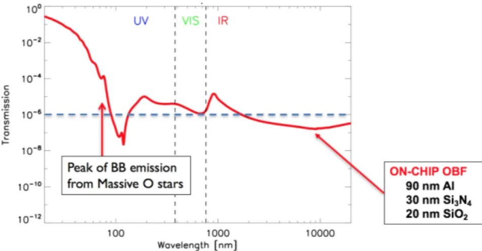
In the current detector design, an OBF consisting of 90 nm of Al + 30 nm of Si3N4 + 20 nm of SiO2 is deposited onto the
chip[12]. Figure 1 shows the modelled transmission of the on-chip OBF in UV/Vis/IR, derived by the matrix formulation of the electromagnetic field boundary conditions[13], using the aluminum refractive index from[13][15] and the Al2O3,
SiO2 and Si3N4 one from[15][16].
Figure 1. Modelled transmission of the multi-layer optical blocking filter deposited on the DEPFET array. The dashed horizontal line corresponds to a filter attenuation of 10-6 which is sufficient to reduce the UV/Vis flux to not affect spectroscopy for most astrophysical sources.
While the on-chip OBF is capable to provide an attenuation of nearly 10-5 in the UV/Vis range, it does not provide
sufficient attenuation at short wavelengths, where the black body emission of hot stars has its peak. In particular, the on-chip OBF is not sufficient for the WFI to observe hot stars brighter than mV ~ 8.5. On the other hand, the capability to
observe hot stars as bright as mV = 2 is mandatory to perform studies of X-ray variability to probe the dynamics of stellar
winds in O-B stars, and to study stellar clusters which contain early-type stars as bright as mV = 4[17]. The use of an
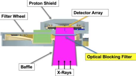
additional OBF mounted on a filter wheel (FW) is thus necessary. In addition, the FW will provide an open aperture, a closed position and calibration sources[18]. Figure 2 shows a schematic drawing of the WFI showing the position of the FW OBF in the context of the main instrument subsystems.
Figure 2. Schematic drawing of the WFI main components, showing the location of the FW OBF.
Based on a consolidated heritage from previous missions such as Chandra[18][19], XMM-Newton[20][22][23], and Hitomi[24][25], as well as investigations performed for LOFT[26], the use of a thin polyimide film 150 nm thick coated with 30 nm of aluminum has been proposed as additional OBF to be mounted on the WFI FW[11]. The combination of the on-chip OBF and the above FW OBF provides an average transmission in the UV/Vis lower than 10-6 and is very efficient in attenuating the spectral range where the hot stars have their maximum emission. Figure 3 shows the modelled transmission of the combination of the two OBFs with the refractive index of polyimide derived from[15][27].
Figure 3. Modelled transmission of the on-chip OBF combined with the additional FW OBF. The dashed horizontal line corresponds to a filter attenuation of 10-6 which is sufficient to reduce the UV/Vis flux to not affect spectroscopy for most astrophysical sources.
Figure 4 shows the calculated number of electron-hole pairs per pixel within an integration time interval (1.3 ms) generated by the observation of early-type stars by the WFI large detector array (LDA) without (solid lines) and with the addition of the FW OBF (dashed line). The calculation is performed according to[11]. The main difference with respect to the previous calculation is due to a better modeling of the FW OBF transmission at wavelengths < 100 nm obtained by use of the refractive index of polyimide calculated from the atomic scattering factors in[15]. The calculated modelling assumes that a 3.5 nm of aluminum are oxidized on each side[28]. The use of the FW OBF provides the additional attenuation necessary to observe hot stars as bright as mv = 2.
Figure 4. Predicted number of electron-hole pairs per pixel for the WFI generated by observation of early-type stars without (solid lines) and with the addition of the FW OBF (dashed line).
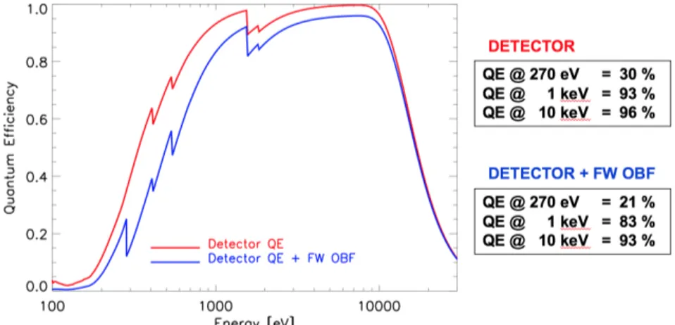
Although the FW OBF is very thin and made of light materials, it absorbs soft X-rays reducing the overall detector QE. In addition, the thick mesh gives a flat QE loss of ~ 3.5%. The WFI QE with the FW OBF in place (Figure 5) is, however, compliant with the scientific requirements, namely > 20% @ 0.270 keV, > 80% @ 1 keV and > 90% @ 10 keV[28].
Figure 5: Quantum efficiency of the WFI LDA without (red) and with the FW OBF in place (blue).
2.1 The Large Detector Array OBF
The WFI LDA consists of 4 quadrants each with 512 Î 512 pixels separated by a ~5 mm wide gap. The full size of the detector is thus ~ 138 mm Î 138 mm. Considering that the filter wheel is located ~100 mm above the focal plane (see
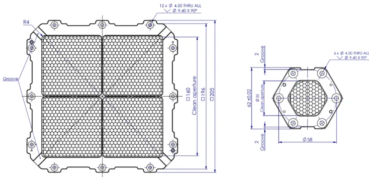
Figure 2), and given the telescope aperture angle, the LDA OBF must be larger than ~ 160 mm Î 160mm. To keep some margin on the gap size between the LDA quadrants and on the positioning of the filter wheel, we have currently designed the LDA OBF with a conservative open area of 170 mmÎ170 mm.
Given this very large size, and knowing that the filter will have to withstand severe acoustic and vibration loads during launch, the use of a reinforcing structure to mechanically support the thin aluminized polyimide film has been investigated. Based on the results of structural analysis under static load, we have chosen a mesh design with square pattern and wires parallel to the square frame diagonal[11]. The selected mesh thickness is 200 µm, the bar width is 100 µm, and the pitch is 6 mm. In addition to the use of a mesh, we have also introduced in the frame design a cross shaped stiffener, dividing the filter in four equal quadrants. It reduces the mesh stress peak and deformation, under uniform static pressure, increasing, at the same time, the dynamic resonance frequencies. The bars of the cross shaped stiffener are 2 mm wide and 6 mm thick.
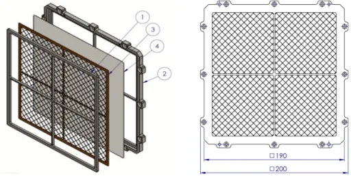
The LDA OBF is composed of four parts, namely: 1) inner frame, 2) outer frame, 3) mesh, 4) polyimide/Al film (Figure 6 left panel). These are glued together by use of Epotek 302-3M Black epoxy resin, to ensure mechanical stiffness, electrical and thermal conductivity.
Figure 6. Left panel shows the mounting scheme of the LDA OBF, consisting of four parts glued together: 1) inner frame, 2) outer frame, 3) mesh, 4) polyimide/Al film. Right panel is a front view of the assembled filter, showing the mesh with square cells and wires parallel to the frame diagonals, and the cross shaped stiffener.
2.2 The Fast Detector OBF
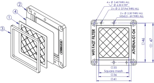
The FD size is ~ 8.3 mm Î 8.3 mm and its distance from the FW will range between 65 mm and 88 mm (to be determined). The FDA OBF size must be, therefore, larger than 25 mm Î 25 mm. To keep some margins on the positioning of the filter wheel from the focal plane and on the telescope defocusing range, we have currently designed the FD OBF with a conservative open area of 35 mm Î 35 mm (Figure 7). Even if the FD OBF is much smaller than the LDA OBF, we baseline to use the same type of supporting mesh and frame mounting.
Figure 7. Left panel shows the mounting scheme of the FDA OBF, consisting of four parts glued together: 1) mesh, 2) outer frame, 3) inner frame, 4) polyimide/Al film. Right panel shows a front view of the assembled FDA OBF.
3. CHARACTERIZATION TESTS SUPPORTING THE DESIGN
In order to support the design consolidation of the WFI OBFs, and to start increasing the technology readiness level (TRL) of the proposed technology, we have procured/manufactured several different filter test samples. Such samples can be divided in two main sets (samples numbering is chronological with first samples procured in October 2015, and last ones in March 2018): 1) small size witness samples for optical properties characterization and surface analysis, mounted on standard TF111 LUXEL frames with 15 mm inner diameter; 2) large size samples, with representative meshes and thick polypropylene films, replacing the thin polyimide, aimed at testing the mechanical properties of the meshes, or with representative meshes (including the gold plating) and representative thin aluminized polyimide films aimed at testing the mechanical properties of the thin membranes.
1. Small size witness samples
- sample #1: 150 nm LUXFilm® polyimide/30 nm Al, meshless; - sample #2: 150 nm LUXFilm® polyimide, meshless.
2. Large size samples
- sample #3: 600 nm polypropylene (BASF Novolen 1302L)/40 nm Ti, 170 mm Î 170 mm, SS mesh; - sample #4: 600 nm polypropylene (BASF Novolen 1302L)/40 nm Ti, 84 mm Î 84 mm (one quadrant),
stainless steel (SS) mesh;
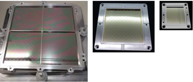
- sample #5: 150 nm LUXFilm® polyimide/30 nm Al, 84 mm Î 84 mm (one quadrant), Au plated SS mesh; - sample #6: 150 nm LUXFilm® polyimide/30 nm Al, 34 mm Î 34 mm (fast detector OBF), meshless option. The mesh has 6 mm pitch, 200 µm bar thickness, and 100 µm bar width. Figure 8 shows pictures of sample #3 partially representative of the LDA OBF, #4 fully representative of one quadrant of the LDA OBF, and #5 representative of the FDA OBF in the meshless option (not the baseline).
Figure 8. Pictures of sample #3 (left), partially representative of the LDA OBF; #4 (center), fully representative of one quadrant of the LDA OBF; #5 (right), representative of the FDA OBF in the meshless option, presently not the baseline.
Preliminary results have been reported elsewhere on optical characterization and surface analysis investigations[28], on vibration tests performed on the large size sample #3 at the Centre Spatial de Liege in March 2017, and on acoustic tests performed at the AGH University in Krakow in May 2017[8]. Here we report some results from further optical characterization measurements and mechanical tests performed on new filter samples.
3.1 Transmission measurements and modelling
Figure 9 shows a comparison between UV/Vis/IR transmission modelling and measurements performed with different instruments on a sample of 150 nm LUXFilm® polyimide/30 nm Al film, meshless. The calculations are derived by using the matrix formulation of the electromagnetic field boundary conditions[13], with the refractive index of aluminum and polyimide derived from[13][15][27].
Figure 9. Modelled UV/VIS/IR transmission (red solid line) for a filter sample consisting of 150 nm LUXFilm® Polyimide/30 nm Al film, meshless compared with measurements performed with different instruments.
The best fit modelling is consistent with a total amount of 7 nm of aluminum oxide, which suggests that the same amount of oxide forms at the interface with the polyimide and on the open surface that we measured with the XPS at the BACH beamline of the ELETTRA Synchrotron (Basovizza, IT)[28]. The UV modelling also fits well with the soft X-ray measurements performed at the BEAR beamline of ELETTRA.
3.2 Vibration tests
A new vibration test campaign was performed in November 2017 at the Max-Planck-Institut fuer Extraterrestrische Physik (MPE). Sine, random, and shock vibration tests, carried out using an UD T-1000 shaker, were aimed at testing the performance of the thin polyimide/Al film supported by a representative Au plated SS mesh (sample #5), and a filter sample with thin polyimide/Al, without mesh, mounted on the FDA frame (sample #6). The adopted reference sine and random vibration test levels derived from the Ariane 5 launcher manual[31] are reported in Table 1. Increasing load levels were applied to the filters while approaching the reference level, with shorter duration with respect to the reference level in order to reduce the risk of fatigue failure. The reference level and higher levels were maintained for the duration specified in the qualification reference (Table 1).
Table 1. Sine and random vibration load reference levels.
Sine (25.0 g 0-peak, sweep rate=2 Oct/min) Random (16.9 g RMS, duration=150 s)
Frequency range (Hz) Level
5.0 – 23.0 11.7 mm (0-peak) 23.0 – 100.0 25.0 g (0-peak) Frequency range (Hz) PSD 20.0 – 100.0 +3.00 dB/oct 100.0 – 300.0 0.5 g2/Hz 300.0 – 2000.0 -5.00 dB/oct
Both tested WFI OBF filter samples survived in-plane reference vibration levels and out-of-plane vibration levels increased by +10g 0-peak sine load and + 3dB random load with respect to the reference levels. Filters have also survived out-of-plane shock reference tests according to the load level specified in Table 2.
Table 2. Shock test reference revel (axial), Q = 10
Frequency (Hz) SRS(g)
100 20
1000 400
3000 400
3.3 Acoustic tests
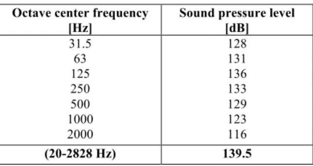
A second acoustic test campaign has been conducted in the reverberation chamber of the Mechanics and Vibro-acoustic Department of the AGH University in Krakow on April 2018, in order to test the performance of a representative thin polyimide/Al film supported by an Au plated SS mesh inside a filter wheel assembly (FWA) mock-up. The acoustic noise reference spectrum adopted for the test campaign has been derived from the Ariane 5 launcher manual[31], and is reported in Table 3. The last row is the SPL integrated over the full frequency range 20-2028 Hz.
Table 3. Acoustic noise reference spectrum.
Octave center frequency [Hz]
Sound pressure level [dB] 31.5 128 63 131 125 136 250 133 500 129 1000 123 2000 116 (20-2828 Hz) 139.5
Acoustic tests were performed with a wide band spectrum as close as possible to the reference one. Increasing load levels were applied starting at a sound pressure level (SPL) of 110 dB at the peak of the spectrum (approx. 125 Hz) and raising the level by 6 dB steps up to 128 dB. At higher levels, up to the maximum, the level was increased at 3 dB steps. Every test lasted 30 s up to the highest level, maintained for 120 s. Figure 10 left panel shows the two tested filter samples mounted on the filter wheel mock-up designed and built at CBK in Warsaw. The FW was assembled inside an ISO 7 clean room, then closed inside a plastic foil tent, and finally transported to the reverberation chamber located in a different building of the campus (Figure 10 right panel).
Figure 10. The left panel shows the two OBF test samples mounted on the filter wheel before closing the FWA with the top cover plate. The right panel shows the FWA mock-up closed inside the plastic tent positioned inside the reverberation chamber at AGH University in Krakow.
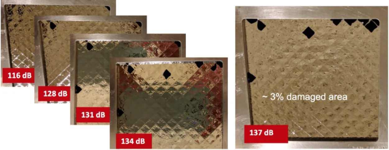
The FD OBF sample, unsupported by mesh, was found broken in the first visual inspection after the acoustic test performed with a maximum SPL of 116 dB @ 125 Hz. Unfortunately, no visual inspection of the filter was performed since its mounting on the filter wheel in ISO7 clean room (Figure 10, left panel), thus the damage could have as well occurred during the FWA assembling, closing the FWA in the tent, and transportation from the ISO7 clean-room to the reverberation chamber located in a different building of the AGH campus. At the first visual inspection, the LDA OBF sample presented a broken cell in a corner (Figure 11, left). The number of broken cells increased as the SPL was incremented up to the reference level; at that point, nearly 3% of the filter area was damaged. No damage was found on the mesh. Figure 11 shows pictures of the test sample #5 taken after the acoustic tests performed at increasing SPL.
Figure 11. Pictures of the test filter sample #5, representative of a single quadrant of the LDA OBF, taken after each acoustic test performed at increasing load level with maximum SPL @ 125 Hz ranging from 116 dB to 137 dB. The last value corresponds to the Ariane 5 launch reference acoustic spectrum.
A clear explanation of the results is not yet available, although it is possible that the environment where the filters have been tested was not properly representative and not sufficiently well controlled. In particular, at low frequencies, the measured SPL inside the FWA was significantly higher than outside, at all SPL levels (Figure 12), unlike what we
measured during the previous campaign. Furthermore, the gap between the FWA and the filter wheel, estimated to be 1 mm, was not measured, and it is thus possible that the FW touched the FWA cover due to vibrations induced by the acoustic noise. Parodi et al. (2018)[32] discuss in more details this acoustic test campaign and possible explanations/solutions.
Figure 12. Measured SPL inside the FWA (blue solid line) compared with the measured values inside the protecting tent (red solid line), and outside the tent in the reverberation chamber (red dashed line). Superimposed is also the Ariane 5 reference acoustic spectrum (black solid line).
4. NEXT STEPS TOWARDS DESIGN CONSOLIDATION
The WFI OBFs investigated so far consist of 150 nm thick polyimide film with 30 nm thick aluminum coating. They are supported by gold plated SS 304 mesh with 6 mm pitch, 100 µm bar width, 200 µm bar thickness, and by an aluminum cross stiffening structure (only LDA OBF). The vibration tests performed so far have shown the validity of the investigated design; on the other hand, one of the two acoustic test campaigns conducted on partially representative filter samples has not been successful with nearly 3% of the filter area damaged after the exposure to the Ariane 5 acoustic spectrum qualification level. We briefly discussed here and in [32] possible reasons, related to the non-optimal quality of the tested filter (e.g. wrinkles and possible non-uniform glue distribution) or to the representativeness of the test environment (e.g. gap size between FWA cover and filter wheel) that may have been responsible for the test failure. Before running the acoustic test on fully representative OBF samples, a more flight-representative FWA shall be built and the acoustic environment inside it properly characterized. In addition, since the thin membrane was damaged inside a few cells (Figure 11), we decided to review the frame and mesh design to reduce the stress on the membrane. In particular, for the LDA OBF, we have: (i) reduced the aperture of the filter from 170 Î 170 mm2 to 160 Î 160 mm2, (ii)
rounded all the frame corners and the supporting cross, (iii) changed the mesh pattern from square to hexagonal, and (iv) reduced the pitch from 6 mm to 4.8 mm. In order to keep nearly the same blocking factor, the mesh bars have been reduced to 75 µmÎ 150 µm. For the FDA OBF we have: changed the mesh pattern from square to hexagonal, reduced the pitch from 6 mm to 4.8 mm, and changed the frame shape from square to hexagonal, to better match the mesh cell shape and have a more uniform stress distribution. Figure 13 shows the new designs of the two OBFs. More details on the OBFs design are given in the “Athena - Wide Field Imager Optical Blocking Filters Mechanical Design and Interface Requirements” document[33]. We are currently evaluating to increase the polyimide film thickness from 150 nm to 200 nm. This change would have moderate impact on the X-ray transmission at low energies but the QE requirements would still be met.
Figure 13. Schematic drawings of the revised designs of the LDA OBF (left) and FDA OBF (right). Both have the same type of Au plated supporting mesh SS with 4.8 mm pitch and 75 µm Î150 µm wires.
A set of fully representative OBF samples is under procurement and will undergo acoustic tests in Q4 2018 at AGH in Krakow. New vibration tests will be performed on such filters at MPE in Garching after the acoustic tests. A new requirement will be put to the filter manufacturer LUXEL to provide filter samples with the polyimide film fully stretched and uniformly glued on the mesh.
5. SUMMARY AND CONCLUSIONS
The DEPFET detectors of the Athena WFI are also sensitive to UV/VIS photons with energy larger that the Si band gap (~ 1.1 eV). An optical blocking filter is thus needed in front of the detector to observe X-ray sources with bright UV/Vis counterparts. In the current detector design an OBF consisting of 90 nm of aluminum + 30 nm of Si3N4 + 20 nm of SiO2
is deposited on-chip. This OBF provides an attenuation of nearly 10-5 in the UV/Vis range at wavelengths > 100 nm, but it does not provide sufficient attenuation at shorter wavelengths where the black body radiation of hot stars has its peak emission. An additional OBF mounted on a filter wheel is therefore baselined to cope with bright UV/Vis sources. The currently investigated design for the FW OBF consists of 150 nm thick polyimide film coated with 30 nm of aluminum, supported by a gold plated stainless steel 304 mesh with 6 mm pitch, and 100 µm x 200 µm bars (width x thickness). A cross shaped aluminum structure, overlapping the gap area between the four quadrants of the large detector array, provides additional stiffening to the LDA OBF. The mesh has an average blocking factor of 3.7 %.
The combination of on-chip and FW OBFs allows to observe even the brightest hot stars, without significant energy resolution degradation. The WFI quantum efficiency, including the FW OBF, is consistent with the requirements, namely: 20% at 0.277 eV, 76% at 1 keV, and 84% at 10 keV.
Vibration tests have been performed on partially representative filter samples at CSL in Liege and at MPE in Garching. Both in-plane and out-of-plane sine and random vibrations, as well as out-of-plane shock tests, have been conducted, demonstrating that the investigated FW OBF can withstand vibration loads significantly higher than the Ariane 5 launcher qualification levels. New tests are ongoing on partially representative samples to measure structural parameters (e.g. damping coefficient), necessary to constraint finite element method modelling.
Two acoustic test campaigns have been performed at AGH University in Krakow on partially representative filter samples mounted inside a basic filter wheel assembly mock-up. The first acoustic test campaign was performed on a full size LDA OBF (sample #3), with representative frame and mesh and ~700 nm thick polypropylene film replacing the thinner polyimide film. Such filter survived a sound pressure level significantly higher than the Ariane 5 qualification level. The second acoustic test campaign was performed on a single quadrant of the LDA OBF, with representative polyimide/Al thin membrane. At the end of the test nearly 3% of the filter area was damaged.
Based on the unsatisfactory results of the second acoustic test campaign, we have reviewed the frame and mesh design of both LDA and FD OBFs, to reduce the stress on the thin polyimide/Al membrane. Fully representative filter samples are under procurement by LUXEL, with a requirement to be fully stretched and uniformly glued on the mesh. A new acoustic test campaign has been scheduled in September 2018. Before testing the new OBFs, the FWA mock-up presently under development at CBK in Warsaw will be fully characterized in the acoustic environment.
Vibration tests will be performed on the new set of fully representative filter samples at MPE in Garching after the acoustic tests.
The results of the scheduled acoustic test campaign will be significant to prove that the FW can be launched in atmospheric pressure. The results of the next acoustic noise test and the next vibration test will be available before the end of the WFI phase A end of 2018.
ACKOWLEDGMENTS
The research leading to these results has received funding from ASI (Italian Space Agency) under the contract n. 2015-046-R.0, from the European Union’s Horizon 2020 Programme under the AHEAD project (grant agreement n. 654215), and from ESA (European Space Agency) under the contract n. 4000120250/17/NL/BJ. We acknowledge fruitful discussions and support by LUXEL corp.
REFERENCES
[1] Barcons, X., et al., “Athena: the X-ray observatory to study the hot and energetic Universe”, Journal of Physics Conference Series, Volume 610, Issue 1, (2015). doi:10.1088/1742-6596/610/1/012008
[2] Nandra, K., et al., “The Hot and Energetic Universe: A White Paper presenting the science theme motivating the Athena+ mission," e-print arXiv:1306.2307 (2013).
[3] Willingale, R., Pareschi, G., Christensen, F., and den Herder, J.-W., "The Hot and Energetic Universe: The Optical Design of the Athena+ Mirror", e-print arXiv:1307.1709W (2013).
[4] Bavdaz, M., et al., “The ATHENA telescope and optics status”, Proc. SPIE, 10399, 103990B (2017).
[5] Barret, D., et al., “The Athena X-ray Integral Field Unit (X-IFU),” Proc. SPIE, 9905, 99052F (2016). doi: 10.1117/12.223243
[6] Pajot, F., et al., “The Athena X-ray Integral Field Unit (X-IFU)”, JLTP, published online first (2018). doi: 10.1007/s10909-018-1904-5
[7] Rau, A., Meidinger, N., Nandra, K., Porro, M., Barret, D., Santangelo, A., Schmid, C., Struder, L., Tenzer, C., Wilms, J., Amoros, C., Andritschke, R., Aschauer, F., Bahr, A., Gunther, B., Furmetz, M., Ott, B., Perinati, E., Rambaud, D., Reiffers, J., Treis, J., von Kienlin, A., Weidenspointner, G., "The Hot and Energetic Universe: The Wide Field Imager (WFI) for Athena+", e-print arXiv:1308.6785 (2013).
[8] Meidinger, N., Barbera, M., Emberger, V., Fürmetz, M., Manhart, M., Müller-Seidlitz, J., Nandra, K., Plattner, M., Rau, A., Treberspurg, W., “The Wide Field Imager instrument for Athena,” Proc. SPIE, 10397, 103970V (2017). doi: 10.1117/12.2271844
[9] Treberspurg W., Andritschke R., Bähr A., Behrens A., Hauser G., Lechner P., Meidinger N., Müller-Seidlitz J., Treis J., "Studies of prototype DEPFET sensors for the Wide Field Imager of Athena," Proc. SPIE, 10397, 103970U (2017). doi: 10.1117/12.2274032
[10] Perinati E., Barbera, M., Diebold S., Guzman A., Santangelo A., Tenzer C., “Preliminary assessment of the ATHENA/WFI non-X-ray background”, Exp Astron., 44, 387 (2017). doi: 10.1007/s10686-017-9541-6
[11] Barbera M., Branduardi-Raymont G., Collura A., Comastri A., Eder J., Kamisiński T., Lo Cicero U., Meidinger N., Mineo T., Molendi S., Parodi G., Pilch A., Piro L., Rataj M., Rauw G., Sciortino L., Waver P., “The optical blocking filter for the ATHENA Wide Field Imager: ongoing activities towards the conceptual design”, Proc. SPIE, 9601, 960109 (2015). doi: 10.1117/12.2189326
[12] Meidinger N., et al., “Development of the wide field imager instrument for ATHENA”, Proc. SPIE, 10699 in press. (2018).
[13] Born M. and Wolf E., "Principles of Optics", 6th ed., Cambridge Univ. Press (UK), ISBN 0521639212 (1997). [14] Aleksandar D. Rakic., "Algorithm for the determination of intrinsic optical constants of metal films: application
to aluminum", Appl. Opt. 34, 4755-4767 (1995). doi: 10.1364/AO.34.004755
[15] Henke B. L. et al.” X-ray interactions: photoabsorption, scattering, transmission, and reflection at E=50-30000 eV, Z=1-92”, Atomic Data and Nuclear Data Tables, 54, 181-342, (1993).
[16] Handbook of Optical Constants of Solids, (1985), Edited by Edward D. Palik, ISBN: 978-0-12-544415-6 [17] Sciortino, S., et al., “The Hot and Energetic Universe: Star formation and evolution”, eprint arXiv:1306.2333
(2013).
[18] Rataj M., Polak S., Palgan T., Kamisiński T., Pilch A., Eder J., Meidinger N., Plattner M., Barbera M., Parodi G., D'Anca F., “The filter and calibration wheel for the ATHENA wide field imager”, Proc. SPIE, 9905, 990568 (2016). doi: 10.1117/12.2235411
[19] Barbera M, Austin K, Collura A, Flanagan A, Jelinsky R, Murray S, Serio S, Zombeck M, "Development of the UV/ion shields for the Advanced X-ray Astrophysics Facility high-resolution camera (AXAF HRC)", Proc. SPIE, 2280, 214-228 (1994). doi: 10.1117/12.186815
[20] Meehan R, Murray S, Zombeck V, Kraft P, Kobayashi K, Chappell H, Kenter T, Barbera M, Collura A, Serio S, "Calibration of the UV/ion shields for the AXAF High-Resolution Camera", Proc. SPIE, 3114, 74-100 (1997). doi: 10.1117/12.283790
[21] Villa G.E., Barbera M., Collura A., La Palombara N., Musso C., Serio S., Stillwell R., Tognon P., Turner D.C., “The optical/UV filters for the EPIC experiment”, IEEE Transactions on Nuclear Science, 45, 921-926 (1998). doi: 10.1109/NSSMIC.1997.672658
[22] Barbera M, Agnello S, Buscarino G, Collura A, Gastaldello F, La Palombara N, Lo Cicero U, Tiengo A, Sciortino, L, Varisco S, Venezia A M, "Status of the EPIC thin and medium filters on-board XMM-Newton after more than 10 years of operation: 1) laboratory measurements on back-up filters", Proc. SPIE, 8859, 885914 (2013). doi: 10.1117/12.2030896
[23] Gastaldello F, Barbera M, Collura A, La Palombara N, Lo Cicero U, Sartore N, Tiengo A, Varisco S, "Status of the EPIC thin and medium filters on-board XMM-Newton after more than 10 years of operation: 2) analysis of in-flight data", Proc. SPIE, 8859, 885915 (2013). doi: 10.1117/12.2030897
[24] Tawara Y., et al., “Development of ultra-thin thermal shield for ASTRO-H x-ray telescopes”, Proc. SPIE 8147, 814704 (2011). doi: 10.1117/12.893368
[25] Iizuka R., Hayashi T., Maeda Y., Ishida M., Tomikawa K., Sato T., Kikuchi N., Okajima T., Soong Y., Serlemitsos P.J., Mori H., Izumiya T., Minami S., "Ground-based x-ray calibration of the Astro-H/Hitomi soft x-ray telescopes", J. Astron. Telesc. Instrum. Syst. 4(1) 011213 (2018). doi: 10.1117/1.JATIS.4.1.011213 [26] Barbera M., Winter B., Coker J., Feroci M., Kennedy T., Walton D., and Zane S., “Baseline design of the filters
for the LAD detector on boad LOFT”, Proc. SPIE, vol. 9144, 914466 (2014). doi: 10.1117/12.2057408
[27] Cavadi A, Artale A, Barbera M, Collura A, Powell R, Varisco S, "Measurement of optical constants n and k of lexan and polyimide", PROC. SPIE, 3765, 805-815 (1999). doi: 10.1117/12.366568
[28] Sciortino, L., Lo Cicero, U., Magnano, E., Píš, I. and Barbera, M. “Surface investigation and aluminum oxide estimation on test filters for the ATHENA X-IFU and WFI detectors,” Proc. SPIE, 9905, 990566 (2016). doi: 10.1117/12.2232376.
[29] Meidinger N., Eder J., Fürmetz M., Nandra K., Pietschner D., Plattner M., Rau A., Reiffers J., Strecker R., Barbera M., Brand T., Wilms J., "Development of the wide field imager for Athena", Proc. SPIE 9601, 96010H (2015). doi: 10.1117/12.2187012
[30] ESA, “Technology Readiness Levels Handbook for Space Applications”, TEC-SHS/5551/MG/ap (2008). [31] ARIANESPACE, “Ariane 5 User’s Manual, Issue 5, Revision 2” (2016)
[32] Parodi G., et Al., “Structural modeling and mechanical tests supporting the design of the ATHENA X-IFU thermal filters and WFI optical blocking filter”, Proc. SPIE 10699, in press. (2018).
[33] Barbera M., and D’Anca F., “ATHENA - Wide Field Imager Optical Blocking Filters Mechanical Design and Interface Requirements”, ATHENA-UNIPA-TR002-2018, issue 1.0 (May 2018).